2014 NISSAN TEANA lock
[x] Cancel search: lockPage 4134 of 4801
STEERING WHEELST-31
< REMOVAL AND INSTALLATION >
C
D E
F
H I
J
K L
M A
B
ST
N
O P
REMOVAL AND INSTALLATION
STEERING WHEEL
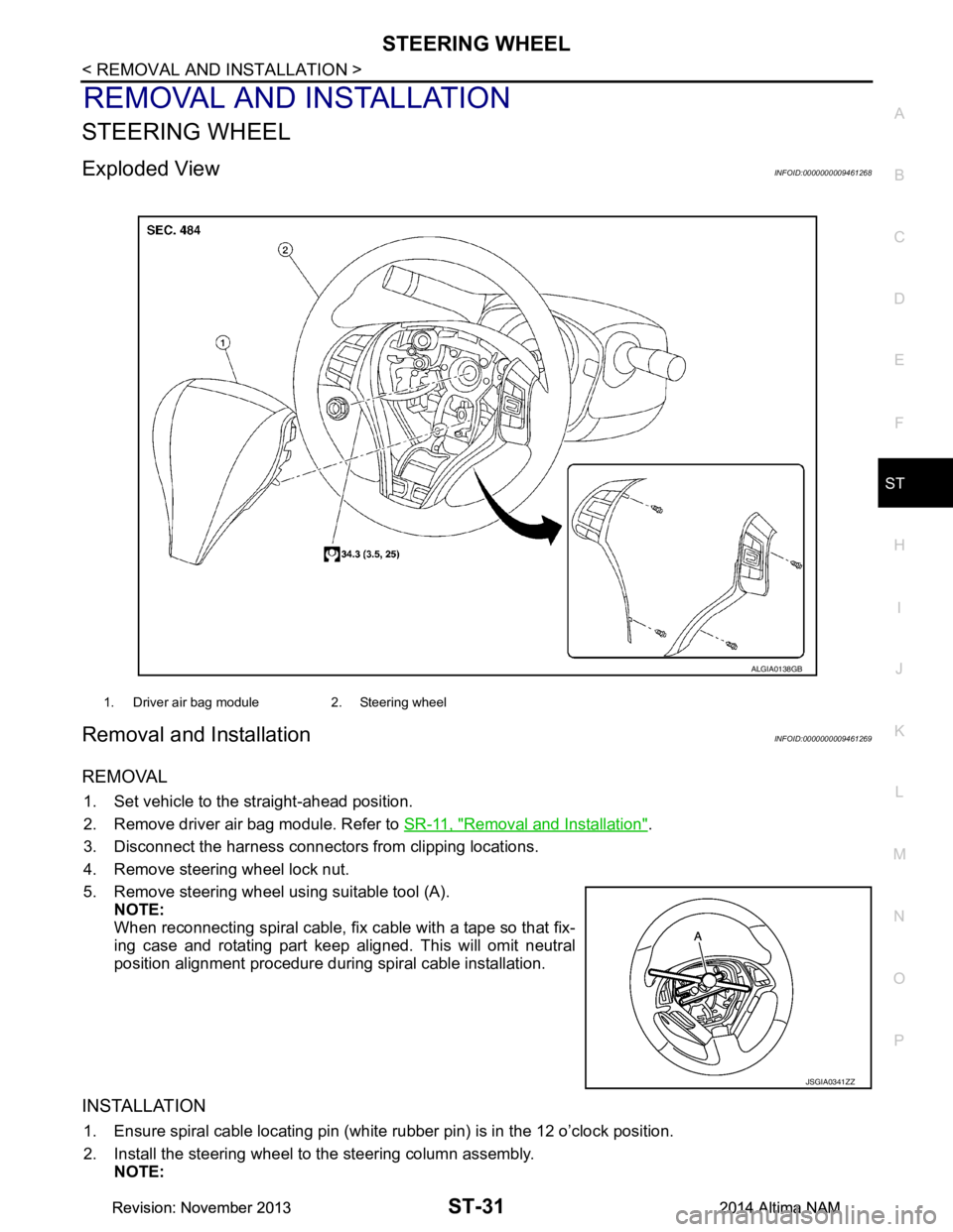
Exploded ViewINFOID:0000000009461268
Removal and InstallationINFOID:0000000009461269
REMOVAL
1. Set vehicle to the straight-ahead position.
2. Remove driver air bag module. Refer to SR-11, "Removal and Installation"
.
3. Disconnect the harness connectors from clipping locations.
4. Remove steering wheel lock nut.
5. Remove steering wheel using suitable tool (A). NOTE:
When reconnecting spiral cable, fix cable with a tape so that fix-
ing case and rotating part keep aligned. This will omit neutral
position alignment procedure during spiral cable installation.
INSTALLATION
1. Ensure spiral cable locating pin (white rubber pin) is in the 12 o’clock position.
2. Install the steering wheel to the steering column assembly. NOTE:
1. Driver air bag module 2. Steering wheel
ALGIA0138GB
JSGIA0341ZZ
Revision: November 20132014 Altima NAMRevision: November 20132014 Altima NAM
Page 4146 of 4801
STEERING GEAR AND LINKAGEST-43
< UNIT DISASSEMBLY AND ASSEMBLY >
C
D E
F
H I
J
K L
M A
B
ST
N
O P
UNIT DISASSEMBLY AND ASSEMBLY
STEERING GEAR AND LINKAGE
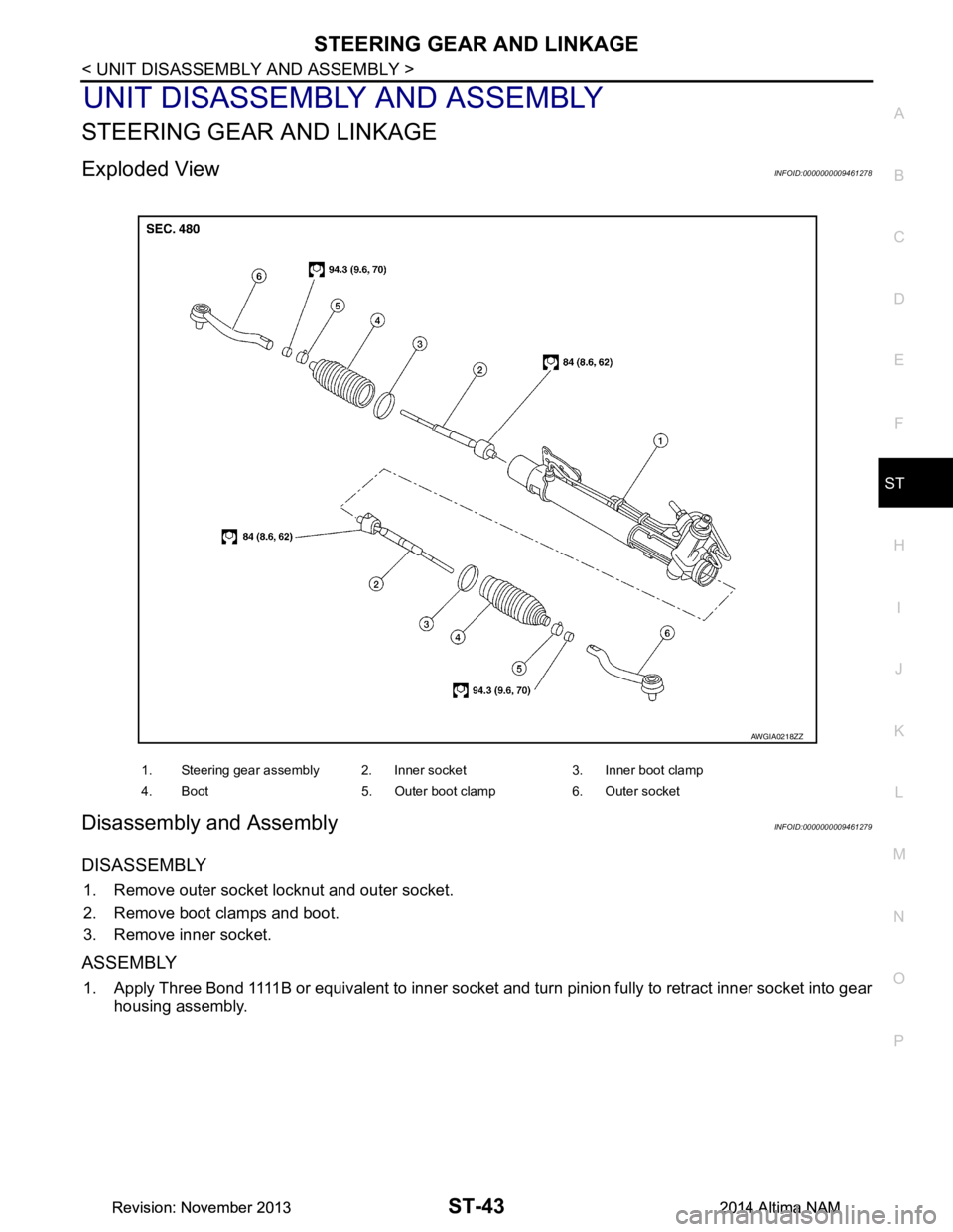
Exploded ViewINFOID:0000000009461278
Disassembly and AssemblyINFOID:0000000009461279
DISASSEMBLY
1. Remove outer socket locknut and outer socket.
2. Remove boot clamps and boot.
3. Remove inner socket.
ASSEMBLY
1. Apply Three Bond 1111B or equivalent to inner socket and turn pinion fully to retract inner socket into gear housing assembly.
1. Steering gear assembly 2. Inner socket 3. Inner boot clamp
4. Boot 5. Outer boot clamp 6. Outer socket
AWGIA0218ZZ
Revision: November 20132014 Altima NAMRevision: November 20132014 Altima NAM
Page 4147 of 4801
ST-44
< UNIT DISASSEMBLY AND ASSEMBLY >
STEERING GEAR AND LINKAGE
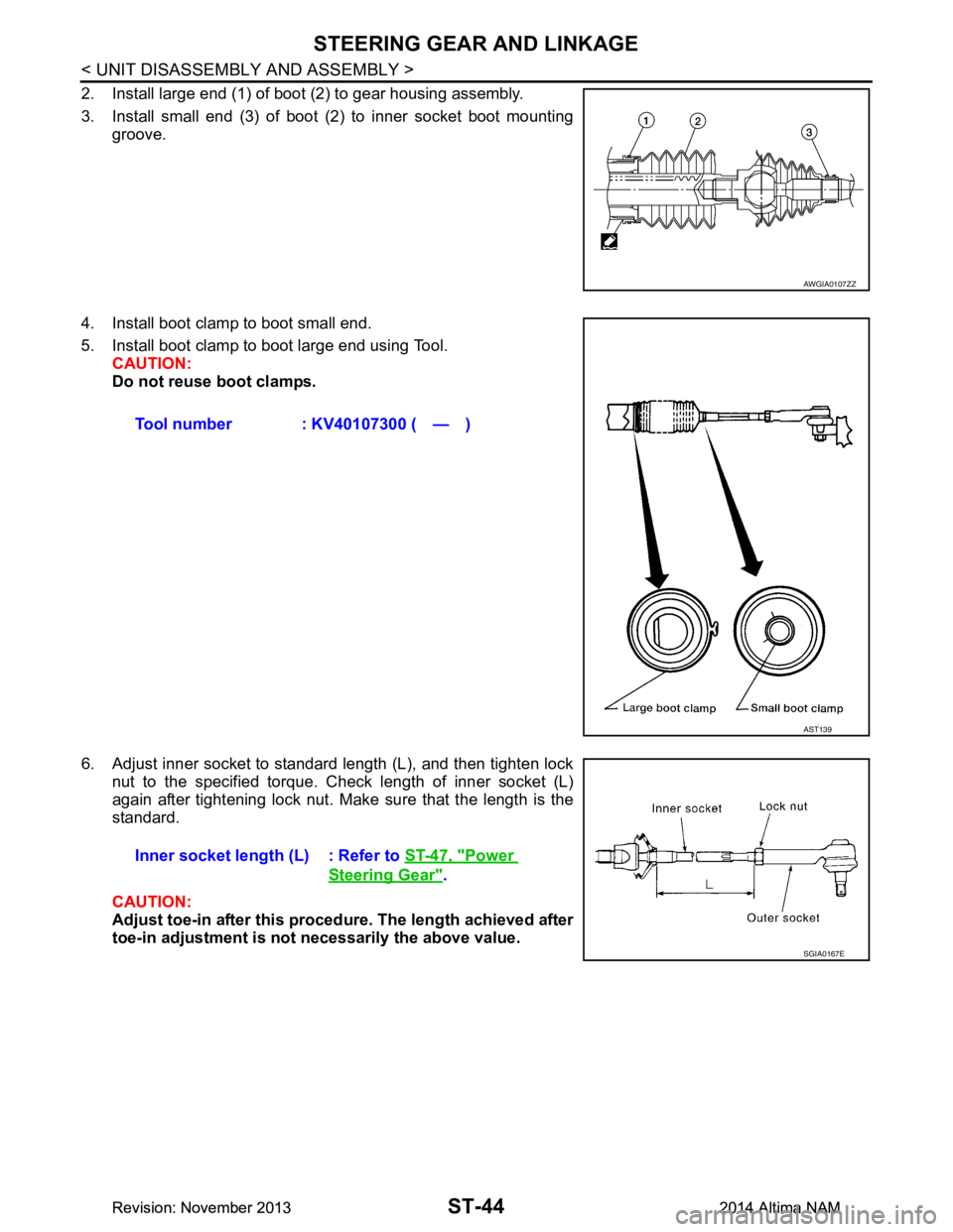
2. Install large end (1) of boot (2) to gear housing assembly.
3. Install small end (3) of boot (2) to inner socket boot mounting groove.
4. Install boot clamp to boot small end.
5. Install boot clamp to boot large end using Tool. CAUTION:
Do not reuse boot clamps.
6. Adjust inner socket to standard length (L), and then tighten lock nut to the specified torque. Check length of inner socket (L)
again after tightening lock nut. Make sure that the length is the
standard.
CAUTION:
Adjust toe-in after this proced ure. The length achieved after
toe-in adjustment is not necessarily the above value.
AWGIA0107ZZ
Tool number : KV40107300 ( — )
AST139
Inner socket length (L) : Refer to ST-47, "Power
Steering Gear".
SGIA0167E
Revision: November 20132014 Altima NAMRevision: November 20132014 Altima NAM
Page 4196 of 4801
STR-6
< SYSTEM DESCRIPTION >
SYSTEM
SYSTEM
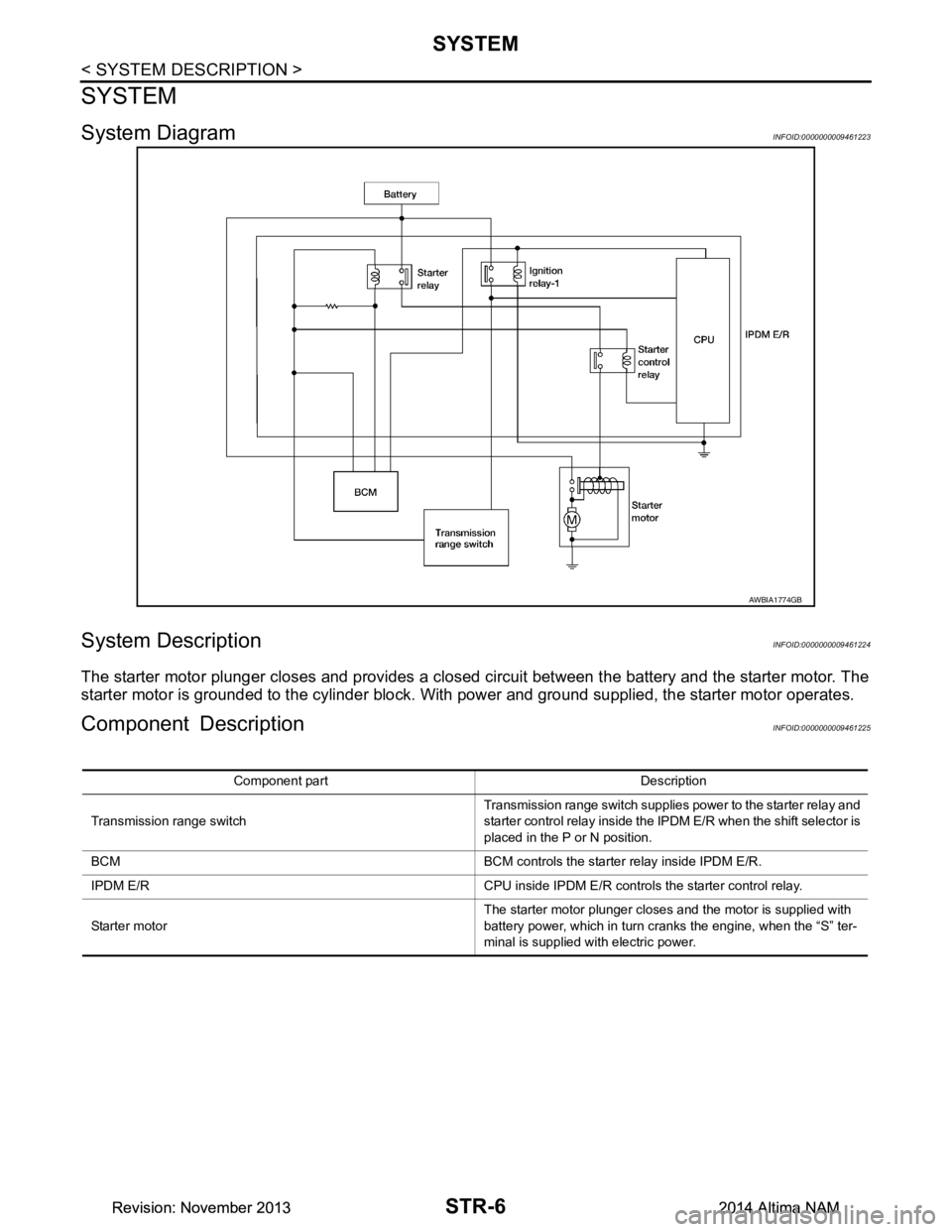
System DiagramINFOID:0000000009461223
System DescriptionINFOID:0000000009461224
The starter motor plunger closes and provides a closed circuit between the battery and the starter motor. The
starter motor is grounded to the cylinder block. With power and ground supplied, the starter motor operates.
Component DescriptionINFOID:0000000009461225
AWBIA1774GB
Component part Description
Transmission range switch Transmission range switch supplies power to the starter relay and
starter control relay inside the IPDM E/R when the shift selector is
placed in the P or N position.
BCM BCM controls the starter relay inside IPDM E/R.
IPDM E/R CPU inside IPDM E/R controls the starter control relay.
Starter motor The starter motor plunger closes and the motor is supplied with
battery power, which in turn cranks the engine, when the “S” ter-
minal is supplied with electric power.
Revision: November 20132014 Altima NAMRevision: November 20132014 Altima NAM
Page 4216 of 4801
TM-1
TRANSMISSION & DRIVELINE
CEF
G H
I
J
K L
M
SECTION TM
A
B
TM
N
O P
CONTENTS
TRANSAXLE & TRANSMISSION
CVT: RE0F10D
PRECAUTION ................ ...............................
9
PRECAUTIONS .............................................. .....9
Precaution for Supplemental Restraint System
(SRS) "AIR BAG" and "SEAT BELT PRE-TEN-
SIONER" ............................................................. ......
9
Precaution for Procedure without Cowl Top Cover ......9
Precaution for TCM and Transaxle Assembly Re-
placement ............................................................ ......
9
General Precautions ...............................................10
On Board Diagnosis (OBD) System of CVT and
Engine ................................................................. ....
11
Removal and Installation Procedure for CVT Unit
Connector ............................................................ ....
11
PREPARATION ...........................................13
PREPARATION .............................................. ....13
Special Service Tools .......................................... ....13
Commercial Service Tools ......................................13
SYSTEM DESCRIPTION .............................14
COMPONENT PARTS ................................... ....14
CVT CONTROL SYSTEM .........................................14
CVT CONTROL SYSTEM : Component Parts Lo-
cation ................................................................... ....
14
CVT CONTROL SYSTEM : TCM ............................16
CVT CONTROL SYSTEM : Transmission Range
Switch .................................................................. ....
16
CVT CONTROL SYSTEM : Primary Speed Sen-
sor ....................................................................... ....
16
CVT CONTROL SYSTEM : Output Speed Sensor ....16
CVT CONTROL SYSTEM : In put Speed Sensor ....17
CVT CONTROL SYSTEM : CVT Fluid Tempera-
ture Sensor .......................................................... ....
17
CVT CONTROL SYSTEM : Primary Pressure
Sensor ................................................................. ....
18
CVT CONTROL SYSTEM : Secondary Pressure
Sensor ................................................................. ....
18
CVT CONTROL SYSTEM : Primary Pressure So-
lenoid Valve ......................................................... ....
19
CVT CONTROL SYSTEM : Secondary Pressure
Solenoid Valve ..................................................... ....
19
CVT CONTROL SYSTEM : Select Solenoid Valve
....
19
CVT CONTROL SYSTEM : Torque Converter
Clutch Solenoid Valve ......................................... ....
19
CVT CONTROL SYSTEM : Line Pressure Sole-
noid Valve ............................................................ ....
20
CVT CONTROL SYSTEM : Overdrive Control
Switch .................................................................. ....
20
CVT CONTROL SYSTEM : O/D OFF Indicator
Lamp .................................................................... ....
20
CVT CONTROL SYSTEM : Shift Position Indica-
tor ........................................................................ ....
20
SHIFT LOCK SYSTEM ..............................................20
SHIFT LOCK SYSTEM : Component Parts Loca-
tion ....................................................................... ....
21
STRUCTURE AND OPERATION .....................22
TRANSAXLE .......................................................... ....22
TRANSAXLE : Cross-Sectional View ......................22
TRANSAXLE : Operation Stat us .............................23
TRANSAXLE : Transaxle Me chanism .....................23
TRANSAXLE : Oil Pressure System .......................26
TRANSAXLE : Component De scription ...................27
FLUID COOLER & FLUID WARMER SYSTEM .... ....27
FLUID COOLER & FLUID WARMER SYSTEM :
System Description .............................................. ....
28
SHIFT LOCK SYSTEM ..............................................28
SHIFT LOCK SYSTEM : Syst em Description ..........28
SYSTEM ...................... ......................................30
CVT CONTROL SYSTEM ..... .....................................30
CVT CONTROL SYSTEM : S ystem Description .....30
Revision: November 20132014 Altima NAMRevision: November 20132014 Altima NAM
Page 4217 of 4801

TM-2
CVT CONTROL SYSTEM : Fail-safe .................. ...31
CVT CONTROL SYSTEM : Protection Control ... ...34
LINE PRESSURE CONTROL ................................ ...35
LINE PRESSURE CONTROL : System Descrip-
tion ....................................................................... ...
35
SHIFT CONTROL ................................................... ...35
SHIFT CONTROL : System Description .................36
SELECT CONTROL ............................................... ...37
SELECT CONTROL : System Description .............38
LOCK-UP CONTROL ............................................. ...38
LOCK-UP CONTROL : System Description ...........38
ON BOARD DIAGNOSTIC (OBD) SYSTEM .....40
Description ........................................................... ...40
Function of OBD .....................................................40
DIAGNOSIS SYSTEM (TCM) ............................41
DIAGNOSIS DESCRIPTION .................................. ...41
DIAGNOSIS DESCRIPTION : 1 Trip Detection Di-
agnosis and 2 Trip Detection Diagnosis .............. ...
41
DIAGNOSIS DESCRIPTION : DTC and DTC of
1st Trip ................................................................. ...
41
DIAGNOSIS DESCRIPTION : Malfunction Indica-
tor Lamp (MIL) ..................................................... ...
41
DIAGNOSIS DESCRIPTION : Counter System .....41
CONSULT Function ................................................43
ECU DIAGNOSIS INFORMATION ..............49
TCM ................................................................. ...49
Reference Value .................................................. ...49
Fail-safe ..................................................................56
Protection Control ...................................................59
DTC Inspection Priority Chart .................................59
DTC Index ..............................................................60
WIRING DIAGRAM .....................................62
CVT CONTROL SYSTEM ............................... ...62
Wiring diagram .................................................... ...62
CVT SHIFT LOCK SYSTEM ........................... ...73
Wiring diagram .................................................... ...73
BASIC INSPECTION ...................................77
DIAGNOSIS AND REPAIR WORK FLOW ..... ...77
Flowchart of Trouble Diagnosis ........................... ...77
Question sheet .......................................................78
ADDITIONAL SERVICE WHEN REPLACING
TCM ................................................................. ...
80
Description ........................................................... ...80
Work Procedure ......................................................80
ADDITIONAL SERVICE WHEN REPLACING
TRANSAXLE ASSEMBLY ............................. ...
81
Description ........................................................... ...81
Work Procedure ................................................... ...81
CVT FLUID ........................................................83
Replacement ........................................................ ...83
Adjustment ..............................................................84
STALL TEST .....................................................86
Work Procedure ................................................... ...86
CVT POSITION ..................................................87
Inspection ............................................................. ...87
Adjustment ..............................................................87
DTC/CIRCUIT DIAGNOSIS ........................88
U0073 COMMUNICATION BUS A OFF ......... ...88
DTC Logic ............................................................ ...88
Diagnosis Procedure ...............................................88
U0100 LOST COMMUNICATION (ECM A) .......89
DTC Logic ............................................................ ...89
Diagnosis Procedure ...............................................89
U0140 LOST COMMUNICATION (BCM) ..........90
DTC Logic ............................................................ ...90
Diagnosis Procedure ...............................................90
U0141 LOST COMMUNICATION (BCM A) ......91
DTC Logic ............................................................ ...91
Diagnosis Procedure ...............................................91
U0155 LOST COMMUNICATION (IPC) ............92
DTC Logic ............................................................ ...92
Diagnosis Procedure ...............................................92
U0300 CAN COMMUNICATION DATA ............93
DTC Logic ............................................................ ...93
Diagnosis Procedure ...............................................93
U1000 CAN COMM CIRCUIT ............................94
Description ........................................................... ...94
DTC Logic ...............................................................94
Diagnosis Procedure ...............................................94
U1117 LOST COMMUNICATION (ABS) ...........95
DTC Logic ............................................................ ...95
Diagnosis Procedure ...............................................95
P062F EEPROM ................................................96
Description ........................................................... ...96
DTC Logic ...............................................................96
Diagnosis Procedure ...............................................96
P0705 TRANSMISSION RANGE SENSOR A ...97
DTC Logic ............................................................ ...97
Diagnosis Procedure ...............................................97
Component Inspection ..........................................101
P0706 TRANSMISSION RANGE SENSOR A ..103
DTC Logic ............................................................ .103
Diagnosis Procedure .............................................103
Component Inspection ..........................................105
Revision: November 20132014 Altima NAMRevision: November 20132014 Altima NAM
Page 4219 of 4801

TM-4
MAIN POWER SUPPLY AND GROUND CIR-
CUIT ................................................................ .
164
Diagnosis Procedure ........................................... ..164
OVERDRIVE CONTROL SWITCH ..................166
Component Function Check ................................ ..166
Diagnosis Procedure .............................................166
Component Inspection ...........................................167
OD OFF INDICATOR LAMP ............................168
Component Function Check ................................ ..168
Diagnosis Procedure .............................................168
SHIFT POSITION INDICATOR CIRCUIT ........169
Component Parts Function Inspection ................ ..169
Diagnosis Procedure .............................................169
SHIFT LOCK SYSTEM ................................... .170
Component Function Check ................................ ..170
Diagnosis Procedure .............................................170
Component Inspection (Shift Lock Solenoid) ........172
Component Inspection (Park Position Switch) ......172
Component Inspection (Stop Lamp Switch) ..........173
SYMPTOM DIAGNOSIS ............................174
CVT CONTROL SYSTEM ............................... .174
Symptom Table ................................................... ..174
PERIODIC MAINTENANCE ..................... ..178
CVT FLUID ...................................................... .178
Inspection ............................................................ ..178
REMOVAL AND INSTALLATION ..............179
CVT SHIFT SELECTOR ................................. .179
Exploded View ..................................................... ..179
Removal and Installation .......................................179
Inspection ..............................................................180
CONTROL CABLE ..........................................181
Exploded View ..................................................... ..181
Removal and Installation .......................................181
Inspection and Adjustment ....................................182
TCM ..................................................................183
Exploded View ..................................................... ..183
Removal and Installation .......................................183
Adjustment .............................................................184
AIR BREATHER HOSE ...................................185
Removal and Installation ..................................... ..185
CONTROL VALVE ...........................................186
Exploded View ..................................................... ..186
Removal and Installation .......................................187
Inspection ..............................................................191
INPUT SPEED SENSOR .................................192
Exploded View ..................................................... ..192
Removal and Installation .......................................192
Inspection and Adjustment ................................... .192
PRIMARY SPEED SENSOR .......................... ..194
Exploded View ..................................................... .194
Removal and Installation .......................................194
Inspection and Adjustment ................................... .194
OUTPUT SPEED SENSOR ..............................196
Exploded View ..................................................... .196
Removal and Installation .......................................196
Inspection and Adjustment ................................... .196
DIFFERENTIAL SIDE OIL SEAL .....................197
Exploded View ..................................................... .197
Removal and Installation .......................................197
Inspection and Adjustment ................................... .198
CVT OIL WARMER SYSTEM ...........................199
WATER HOSE ........................................................ .199
WATER HOSE : Exploded View ...........................199
WATER HOSE : Removal and Installation ...........199
WATER HOSE : Inspection ..................................201
CVT FLUID COOLER HOSE .................................. .201
CVT FLUID COOLER HOSE : Exploded View .....201
CVT FLUID COOLER HOSE : Removal and In-
stallation ............................................................... .
202
CVT FLUID COOLER HOSE : Inspection .............203
CVT OIL WARMER ................................................ .203
CVT OIL WARMER : Exploded View ....................203
CVT OIL WARMER : Removal and Installation ....203
CVT OIL WARMER : Inspection .......................... .204
PLUG ................................................................205
Description ........................................................... .205
Exploded View ......................................................205
Removal and Installation .......................................205
Inspection and Adjustment ................................... .205
UNIT REMOVAL AND INSTALLATION ...206
TRANSAXLE ASSEMBLY ............................. ..206
Exploded View ..................................................... .206
Removal and Installation .......................................206
Inspection and Adjustment ................................... .208
UNIT DISASSEMBLY AND ASSEMBLY ..209
TORQUE CONVERTER AND CONVERTER
HOUSING OIL SEAL ...................................... ..
209
Exploded View ..................................................... .209
Disassembly ..........................................................209
Assembly ..............................................................209
Inspection ..............................................................210
SERVICE DATA AND SPECIFICATIONS
(SDS) ............... ..........................................
212
SERVICE DATA AND SPECIFICATIONS
(SDS) .............................................................. ..
212
Revision: November 20132014 Altima NAMRevision: November 20132014 Altima NAM
Page 4220 of 4801
TM-5
CEF
G H
I
J
K L
M A
B
TM
N
O P
General Specification ..........................................
..
212
Shift Characteristics ..............................................212
Stall Speed ............................................................212
Torque Converter ..................................................212
Heater Thermostat ................................................212
CVT: RE0F10E
PRECAUTION ................ ............................
213
PRECAUTIONS .............................................. ..213
Precaution for Supplemental Restraint System
(SRS) "AIR BAG" and "SEAT BELT PRE-TEN-
SIONER" ............................................................. ..
213
Precaution for Procedure without Cowl Top Cover ..213
Precaution for TCM and Transaxle Assembly Re-
placement ............................................................ ..
213
General Precautions .............................................214
On Board Diagnosis (OBD) System of CVT and
Engine ................................................................. ..
215
Removal and Installation Procedure for CVT Unit
Connector ............................................................ ..
215
PREPARATION .........................................217
PREPARATION .............................................. ..217
Special Service Tools .......................................... ..217
Commercial Service Tools ....................................217
SYSTEM DESCRIPTION ...........................218
COMPONENT PARTS ................................... ..218
CVT CONTROL SYSTEM .......................................218
CVT CONTROL SYSTEM : Component Parts Lo-
cation ................................................................... ..
218
CVT CONTROL SYSTEM : TCM ..........................219
CVT CONTROL SYSTEM : Transmission Range
Switch .................................................................. ..
219
CVT CONTROL SYSTEM : Primary Speed Sen-
sor ....................................................................... ..
219
CVT CONTROL SYSTEM : Output Speed Sensor ..220
CVT CONTROL SYSTEM : Input Speed Sensor ..220
CVT CONTROL SYSTEM : CVT Fluid Tempera-
ture Sensor .......................................................... ..
221
CVT CONTROL SYSTEM : Primary Pressure
Sensor ................................................................. ..
221
CVT CONTROL SYSTEM : Secondary Pressure
Sensor ................................................................. ..
222
CVT CONTROL SYSTEM : Primary Pressure So-
lenoid Valve ......................................................... ..
222
CVT CONTROL SYSTEM : Secondary Pressure
Solenoid Valve .................................................... ..
222
CVT CONTROL SYSTEM : Select Solenoid Valve
..
223
CVT CONTROL SYSTEM : Torque Converter
Clutch Solenoid Valve ......................................... ..
223
CVT CONTROL SYSTEM : Line Pressure Sole-
noid Valve ........................................................... ..
223
CVT CONTROL SYSTEM : Paddle Shifter ...........223
CVT CONTROL SYSTEM : Shift Position Indica-
tor ........................................................................ ..
223
SHIFT LOCK SYSTEM ............................................223
SHIFT LOCK SYSTEM : Component Parts Loca-
tion ....................................................................... ..
224
STRUCTURE AND OPERATION ...................225
TRANSAXLE .......................................................... ..225
TRANSAXLE : Cross-Sectional View ....................225
TRANSAXLE : Operation Stat us ...........................226
TRANSAXLE : Transaxle Me chanism ...................226
TRANSAXLE : Oil Pressure System .....................228
TRANSAXLE : Component De scription .................229
FLUID COOLER & FLUID WARMER SYSTEM .... ..229
FLUID COOLER & FLUID WARMER SYSTEM :
System Description .............................................. ..
230
SHIFT LOCK SYSTEM ............................................230
SHIFT LOCK SYSTEM : Syst em Description ........230
SYSTEM ...................... ....................................232
CVT CONTROL SYSTEM ..... ...................................232
CVT CONTROL SYSTEM : S ystem Description ...232
CVT CONTROL SYSTEM : Fa il-safe ....................233
CVT CONTROL SYSTEM : Pr otection Control .....236
LINE PRESSURE CONTROL ......................... .........237
LINE PRESSURE CONTROL : System Descrip-
tion ....................................................................... ..
237
SHIFT CONTROL .................................................. ..237
SHIFT CONTROL : System Description ................238
SELECT CONTROL ............................................... ..239
SELECT CONTROL : System Description ............239
LOCK-UP CONTROL ............................................ ..240
LOCK-UP CONTROL : System Description ..........240
ON BOARD DIAGNOSTIC (OBD) SYSTEM ..242
Description .............................................................242
Function of OBD ....................................................242
DIAGNOSIS SYSTEM (TCM) ..........................243
DIAGNOSIS DESCRIPTION .................................. ..243
DIAGNOSIS DESCRIPTION : 1 Trip Detection Di-
agnosis and 2 Trip Detection Diagnosis .............. ..
243
DIAGNOSIS DESCRIPTION : DTC and DTC of
1st Trip ................................................................. ..
243
DIAGNOSIS DESCRIPTION : Malfunction Indica-
tor Lamp (MIL) ..................................................... ..
243
DIAGNOSIS DESCRIPTION : Counter System ....243
CONSULT Function ............................................. ..245
ECU DIAGNOSIS INFORMATION ............251
TCM .................................................................251
Reference Value .................................................. ..251
Revision: November 20132014 Altima NAMRevision: November 20132014 Altima NAM