2014 NISSAN TEANA lock
[x] Cancel search: lockPage 3246 of 4801

MIR-16
< SYMPTOM DIAGNOSIS >
SQUEAK AND RATTLE TROUBLE DIAGNOSES
1. Loose harness or harness connectors.
2. Front console map/reading lamp lens loose.
3. Loose screws at console attachment points.
SEATS
When isolating seat noise it's important to note the pos ition the seat is in and the load placed on the seat when
the noise is present. These conditions should be dupl icated when verifying and isolating the cause of the
noise.
Cause of seat noise include:
1. Headrest rods and holder
2. A squeak between the seat pad cushion and frame
3. The rear seatback lock and bracket
These noises can be isolated by moving or pressing on the suspected components while duplicating the con-
ditions under which the noise occurs. Most of thes e incidents can be repaired by repositioning the component
or applying urethane tape to the contact area.
UNDERHOOD
Some interior noise may be caused by components under the hood or on the engine wall. The noise is then
transmitted into the passenger compartment.
Causes of transmitted underhood noise include:
1. Any component installed to the engine wall
2. Components that pass through the engine wall
3. Engine wall mounts and connectors
4. Loose radiator installation pins
5. Hood bumpers out of adjustment
6. Hood striker out of adjustment
These noises can be difficult to isolate since they cannot be reached from the interior of the vehicle. The best
method is to secure, move or insulate one component at a time and test drive the vehicle. Also, engine rpm or
load can be changed to isolate the noise. Repairs can usually be made by moving, adjusting, securing, or
insulating the component causing the noise.
Revision: November 20132014 Altima NAMRevision: November 20132014 Altima NAM
Page 3333 of 4801

MWI-78
< SYMPTOM DIAGNOSIS >
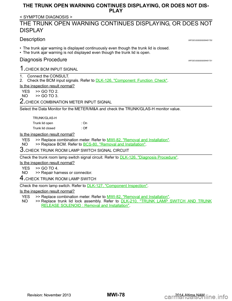
THE TRUNK OPEN WARNING CONTINUES DISPLAYING, OR DOES NOT DIS-
PLAY
THE TRUNK OPEN WARNING CONTIN UES DISPLAYING, OR DOES NOT
DISPLAY
DescriptionINFOID:0000000009461750
• The trunk ajar warning is displayed continuously even though the trunk lid is closed.
• The trunk ajar warning is not displayed even though the trunk lid is open.
Diagnosis ProcedureINFOID:0000000009461751
1.CHECK BCM INPUT SIGNAL
1. Connect the CONSULT.
2. Check the BCM input signals. Refer to DLK-126, "Component Function Check"
.
Is the inspection result normal?
YES >> GO TO 2.
NO >> GO TO 3.
2.CHECK COMBINATION METER INPUT SIGNAL
Select the Data Monitor for the METER/M &A and check the TRUNK/GLAS-H monitor value.
Is the inspection result normal?
YES >> Replace combination meter. Refer to MWI-82, "Removal and Installation".
NO >> Replace BCM. Refer to BCS-80, "Removal and Installation"
.
3.CHECK TRUNK ROOM LAMP SWITCH SIGNAL CIRCUIT
Check the trunk room lamp switch signal circuit. Refer to DLK-126, "Diagnosis Procedure"
.
Is the inspection result normal?
YES >> GO TO 4.
NO >> Repair harness or connector.
4.CHECK TRUNK ROOM LAMP SWITCH
Check the room lamp switch. Refer to DLK-127, "Component Inspection"
.
Is the inspection result normal?
YES >> Replace combination meter. Refer to MWI-82, "Removal and Installation".
NO >> Replace trunk lid lock assembly. Refer to DLK-210, "TRUNK LAMP SWITCH AND TRUNK
RELEASE SOLENOID : Removal and Installation".
TRUNK/GLAS-H
Trunk lid open : On
Trunk lid closed : Off
Revision: November 20132014 Altima NAMRevision: November 20132014 Altima NAM
Page 3336 of 4801

MWI
NORMAL OPERATING CONDITIONMWI-81
< SYMPTOM DIAGNOSIS >
C
D E
F
G H
I
J
K L
M B
A
O P
NORMAL OPERATING CONDITION
COMPASS
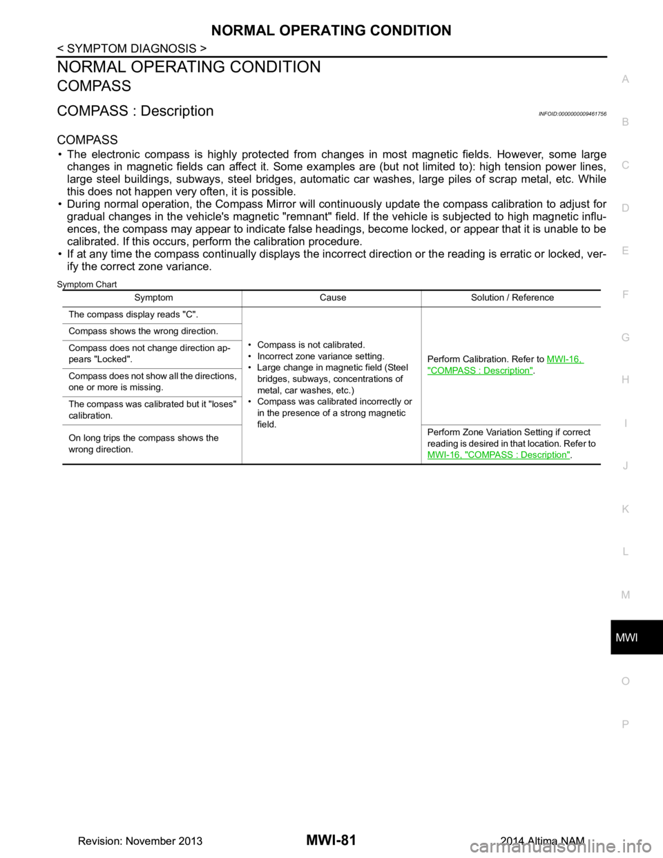
COMPASS : DescriptionINFOID:0000000009461756
COMPASS
• The electronic compass is highly protected from changes in most magnetic fields. However, some large
changes in magnetic fields can affect it. Some exampl es are (but not limited to): high tension power lines,
large steel buildings, subways, steel bridges, automatic car washes, large piles of scrap metal, etc. While
this does not happen very often, it is possible.
• During normal operation, the Compass Mirror will cont inuously update the compass calibration to adjust for
gradual changes in the vehicle's magnetic "remnant" field. If the vehicle is subjected to high magnetic influ-
ences, the compass may appear to indicate false headings , become locked, or appear that it is unable to be
calibrated. If this occurs, perform the calibration procedure.
• If at any time the compass continually displays the inco rrect direction or the reading is erratic or locked, ver-
ify the correct zone variance.
Symptom Chart
Symptom Cause Solution / Reference
The compass display reads "C".
• Compass is not calibrated.
• Incorrect zone variance setting.
• Large change in magnetic field (Steel bridges, subways, concentrations of
metal, car washes, etc.)
• Compass was calibrated incorrectly or
in the presence of a strong magnetic
field. Perform Calibration. Refer to
MWI-16,
"COMPASS : Description".
Compass shows the wrong direction.
Compass does not change direction ap-
pears "Locked".
Compass does not show all the directions,
one or more is missing.
The compass was calibrated but it "loses"
calibration.
On long trips the compass shows the
wrong direction. Perform Zone Variatio
n Setting if correct
reading is desired in that location. Refer to
MWI-16, "COMPASS : Description"
.
Revision: November 20132014 Altima NAMRevision: November 20132014 Altima NAM
Page 3342 of 4801

PB-4
< BASIC INSPECTION >
PARKING BRAKE SYSTEM
BASIC INSPECTION
PARKING BRAKE SYSTEM
InspectionINFOID:0000000009462912
PEDAL STROKE
1. Operate parking brake pedal with a force of 196 N (20.0 kg-f, 44.1 lb-f), make sure pedal stroke is within
the specified number of notches. (Check it by listening and counting ratchet clicks.)
2. When brake warning lamp turns ON, check that the pedal stroke is within the specified number of notches. (Check it by listening to the clicks of the ratchet.)
INSPECT COMPONENTS
• Make sure that the mounting conditions (loosenes s, backlash, etc.) of each component are normal.
• Check the following:
- Device assembly for bend, damage and cracks. Replace if necessary.
- Cables and equalizer for wear and damage. Replace if necessary.
- Parking brake switch. Replace if necessary.
AdjustmentINFOID:0000000009462913
ADJUSTMENT
1. Remove rear wheel and tire using power tool. Refer to WT-55, "Adjustment".
2. Insert a deep socket wrench onto adjusting nut. Rotate adjusting nut to fully loosen cable, and then release parking brake pedal.
3. Secure both disc rotors to hubs using wheel nuts so as not to tilt the disc rotors.
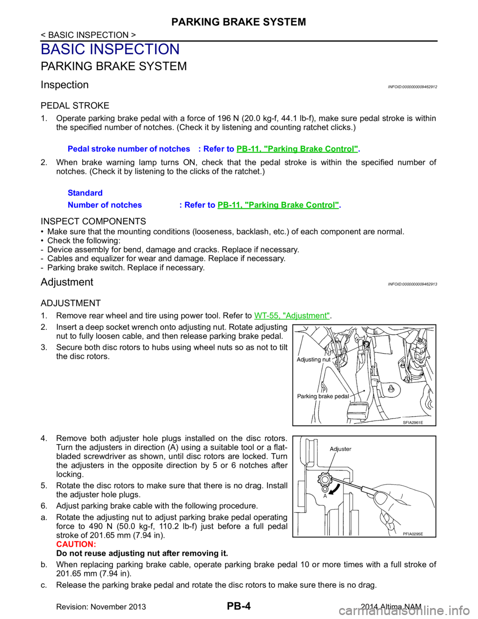
4. Remove both adjuster hole plugs installed on the disc rotors. Turn the adjusters in direction (A) using a suitable tool or a flat-
bladed screwdriver as shown, until disc rotors are locked. Turn
the adjusters in the opposite direction by 5 or 6 notches after
locking.
5. Rotate the disc rotors to make sure that there is no drag. Install the adjuster hole plugs.
6. Adjust parking brake cable with the following procedure.
a. Rotate the adjusting nut to adjust parking brake pedal operating force to 490 N (50.0 kg-f, 110.2 lb-f) just before a full pedal
stroke of 201.65 mm (7.94 in).
CAUTION:
Do not reuse adjusting nut after removing it.
b. When replacing parking brake cable, operate parking brake pedal 10 or more times with a full stroke of 201.65 mm (7.94 in).
c. Release the parking brake pedal and rotate the disc rotors to make sure there is no drag. Pedal stroke number of notches : Refer to
PB-11, "Parking Brake Control"
.
Standard
Number of notches : Refer to PB-11, "Parking Brake Control"
.
SFIA2961E
PFIA0295E
Revision: November 20132014 Altima NAM
Page 3345 of 4801

PARKING BRAKE CONTROLPB-7
< REMOVAL AND INSTALLATION >
C
D E
G H
I
J
K L
M A
B
PB
N
O P
REMOVAL AND INSTALLATION
PARKING BRAKE CONTROL
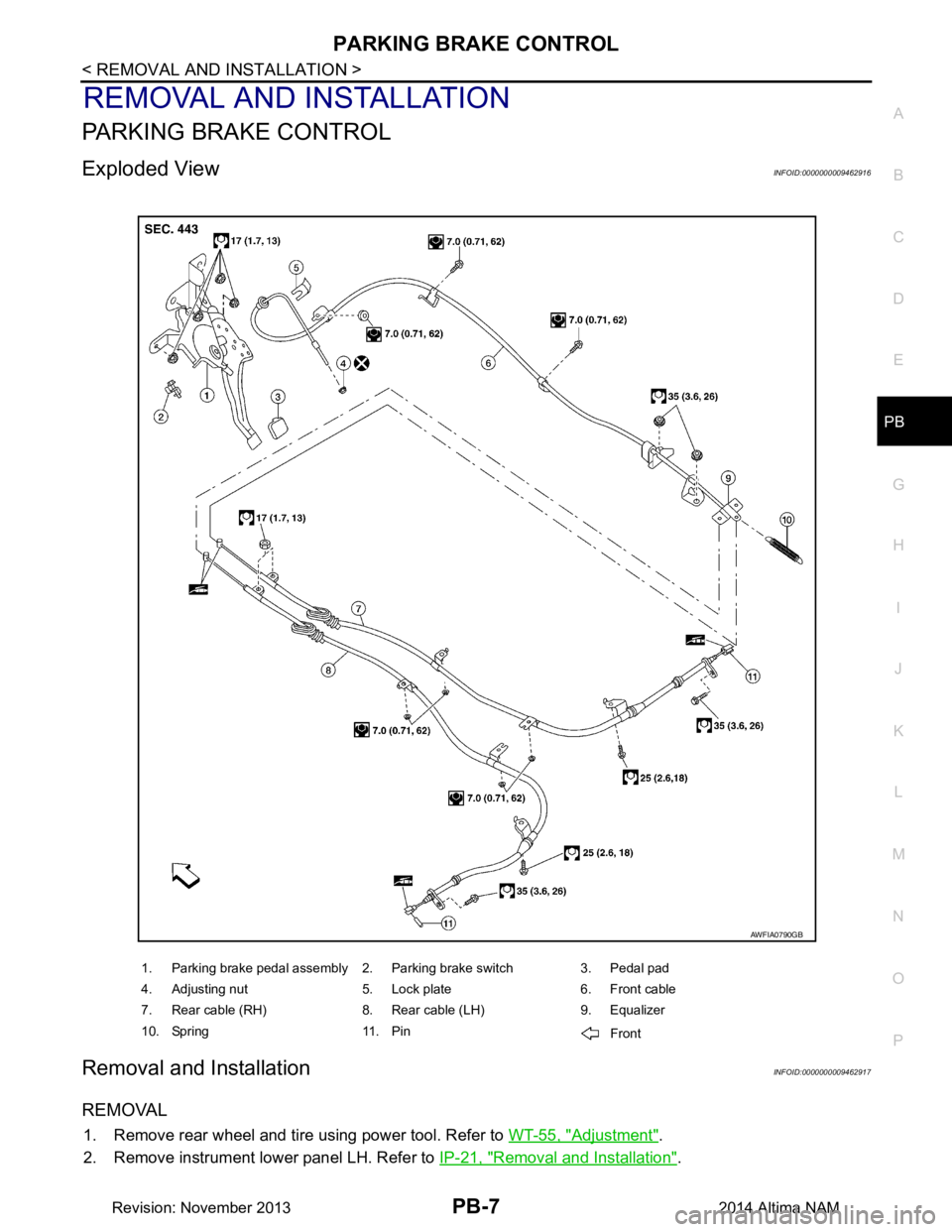
Exploded ViewINFOID:0000000009462916
Removal and InstallationINFOID:0000000009462917
REMOVAL
1. Remove rear wheel and tire using power tool. Refer to WT-55, "Adjustment".
2. Remove instrument lower panel LH. Refer to IP-21, "Removal and Installation"
.
1. Parking brake pedal assembly 2. Parking brake switch 3. Pedal pad
4. Adjusting nut 5. Lock plate 6. Front cable
7. Rear cable (RH) 8. Rear cable (LH) 9. Equalizer
10. Spring 11. Pin Front
AWFIA0790GB
Revision: November 20132014 Altima NAM
Page 3359 of 4801
![NISSAN TEANA 2014 Service Manual
PCS-10
< SYSTEM DESCRIPTION >[IPDM E/R]
DIAGNOSIS SYSTEM (IPDM E/R)
APPLICATION ITEM
CONSULT performs the following functions
via CAN communication with IPDM E/R.
ECU IDENTIFICATION
The IPDM E/R par NISSAN TEANA 2014 Service Manual
PCS-10
< SYSTEM DESCRIPTION >[IPDM E/R]
DIAGNOSIS SYSTEM (IPDM E/R)
APPLICATION ITEM
CONSULT performs the following functions
via CAN communication with IPDM E/R.
ECU IDENTIFICATION
The IPDM E/R par](/manual-img/5/57390/w960_57390-3358.png)
PCS-10
< SYSTEM DESCRIPTION >[IPDM E/R]
DIAGNOSIS SYSTEM (IPDM E/R)
APPLICATION ITEM
CONSULT performs the following functions
via CAN communication with IPDM E/R.
ECU IDENTIFICATION
The IPDM E/R part number is displayed.
SELF DIAGNOSTIC RESULT
Refer to PCS-20, "DTC Index".
DATA MONITOR
Direct Diagnostic Mode Description
Ecu Identification The IPDM E/R part number is displayed.
Self Diagnostic Result The IPDM E/R self diagnostic results are displayed.
Data Monitor The IPDM E/R input/output data is displayed in real time.
Active Test The IPDM E/R activates outputs to test components.
CAN Diag Support Mntr The result of transmit/receive diagnosis of CAN communication is displayed.
Monitor Item [Unit] Main
Signals Description
MOTOR FAN REQ [%] ×Indicates cooling fan speed signal received from ECM on CAN communication
line
AC COMP REQ [On/Off] ×Indicates A/C compressor request signal received from ECM on CAN commu-
nication line
TAIL&CLR REQ [On/Off] ×Indicates position light request signal received from BCM on CAN communica-
tion line
HL LO REQ [On/Off] ×Indicates low beam request signal received from BCM on CAN communication
line
HL HI REQ [On/Off] ×Indicates high beam request signal received from BCM on CAN communication
line
FR FOG REQ [On/Off] ×Indicates front fog light request signal received from BCM on CAN communica-
tion line
FR WIP REQ [Stop/1LOW/Low/Hi] ×Indicates front wiper request signal received from BCM on CAN communication
line
WIP AUTO STOP [STOP P/ACT P] ×Indicates condition of front wiper auto stop signal
WIP PROT [Off/BLOCK] ×Indicates condition of front wiper fail-safe operation
IGN RLY1 -REQ [On/Off] Indicates ignition switch ON signal received from BCM on CAN communication
line
IGN RLY [On/Off] ×Indicates condition of ignition relay
PUSH SW [On/Off] Indicates condition of push-button ignition switch
INTER/NP SW [On/Off] Indicates condition of CVT shift position
ST RLY CONT [On/Off] Indicates starter relay status signal received from BCM on CAN communication
line
IHBT RLY -REQ [On/Off] Indicates starter control relay signal received from BCM on CAN communication
line
ST/INHI RLY [Off/ ST /INHI] Indicates condition of starter relay and starter control relay
DETENT SW [On/Off] Indicates condition of CVT shift selector (park position switch)
DTRL REQ [Off] Indicates daytime light request signal received from BCM on CAN communica-
tion line
HOOD SW [On/Off] Indicates condition of hood switch
THFT HRN REQ [On/Off] Indicates theft warning horn request signal received from BCM on CAN commu-
nication line
Revision: November 20132014 Altima NAMRevision: November 20132014 Altima NAM
Page 3361 of 4801
![NISSAN TEANA 2014 Service Manual
PCS-12
< ECU DIAGNOSIS INFORMATION >[IPDM E/R]
IPDM E/R (INTELLIGENT POWER DI
STRIBUTION MODULE ENGINE ROOM)
ECU DIAGNOSIS INFORMATION
IPDM E/R (INTELLIGENT POWER DISTRIBUTION MODULE ENGINE
ROOM)
Re NISSAN TEANA 2014 Service Manual
PCS-12
< ECU DIAGNOSIS INFORMATION >[IPDM E/R]
IPDM E/R (INTELLIGENT POWER DI
STRIBUTION MODULE ENGINE ROOM)
ECU DIAGNOSIS INFORMATION
IPDM E/R (INTELLIGENT POWER DISTRIBUTION MODULE ENGINE
ROOM)
Re](/manual-img/5/57390/w960_57390-3360.png)
PCS-12
< ECU DIAGNOSIS INFORMATION >[IPDM E/R]
IPDM E/R (INTELLIGENT POWER DI
STRIBUTION MODULE ENGINE ROOM)
ECU DIAGNOSIS INFORMATION
IPDM E/R (INTELLIGENT POWER DISTRIBUTION MODULE ENGINE
ROOM)
Reference ValueINFOID:0000000009461603
VALUES ON THE DIAGNOSIS TOOL
Monitor Item Condition Value/Status
RAD FAN REQ Engine idle speed Changes depending on engine cool-
ant temperature, air conditioner op-
eration status, vehicle speed, etc. 1, 2, 3, 4
AC COMP REQ Engine running A/C switch OFF Off
A/C switch ON
(Compressor is operating) On
TAIL&CLR REQ Lighting switch OFF Off
Lighting switch 1ST, 2ND, HI or AUTO (Light is illuminated) On
HL LO REQ Lighting switch OFF Off
Lighting switch 2ND HI or AUTO (Light is illuminated) On
HL HI REQ Lighting switch OFF Off
Lighting switch HI On
FR FOG REQ Lighting switch 2ND or
AUTO (Light is illuminated) Front fog lamp switch OFF Off
• Front fog lamp switch ON
• Daytime running light activated (Only for Canada models) On
FR WIP REQ Ignition switch ON Front wiper switch OFF STOP
Front wiper switch INT 1LOW
Front wiper switch LO Low
Front wiper switch HI Hi
WIP AUTO STOP Ignition switch ON Front wiper stop position STOP P
Any position other than front wiper
stop position ACT P
WIP PROT Ignition switch ON Front wiper operates normally Off
Front wiper stops at fail-safe opera-
tion BLOCK
IGN RLY1 -REQ Ignition switch OFF or ACC Off
Ignition switch ON On
IGN RLY Ignition switch OFF or ACC Off
Ignition switch ON On
PUSH SW Release the push-button ignition switch Off
Press the push-button ignition switch On
INTER/NP SW Ignition switch ON CVT selector lever in any position
other than P or N Off
CVT selector lever in P or N position On
ST RLY CONT Ignition switch ON Off
At engine cranking On
IHBT RLY -REQ Ignition switch ON Off
At engine cranking On
Revision: November 20132014 Altima NAMRevision: November 20132014 Altima NAM
Page 3362 of 4801
![NISSAN TEANA 2014 Service Manual
PCS
IPDM E/R (INTELLIGENT POWER DISTRIBUTION MODULE ENGINE ROOM)
PCS-13
< ECU DIAGNOSIS INFORMATION > [IPDM E/R]
C
D E
F
G H
I
J
K L
B
A
O P
N
ST/INHI RLY
Ignition switch ON Off
At engine cranking NISSAN TEANA 2014 Service Manual
PCS
IPDM E/R (INTELLIGENT POWER DISTRIBUTION MODULE ENGINE ROOM)
PCS-13
< ECU DIAGNOSIS INFORMATION > [IPDM E/R]
C
D E
F
G H
I
J
K L
B
A
O P
N
ST/INHI RLY
Ignition switch ON Off
At engine cranking](/manual-img/5/57390/w960_57390-3361.png)
PCS
IPDM E/R (INTELLIGENT POWER DISTRIBUTION MODULE ENGINE ROOM)
PCS-13
< ECU DIAGNOSIS INFORMATION > [IPDM E/R]
C
D E
F
G H
I
J
K L
B
A
O P
N
ST/INHI RLY
Ignition switch ON Off
At engine cranking ST →INHI
The status of starter relay or starter control relay cannot be recognized by
the battery voltage malfunction, etc. when the starter relay is ON and the
starter control relay is OFF UNKWN
DETENT SW Ignition switch ON • Press the selector button with
CVT selector lever in P position
• CVT selector lever in any position
other than P Off
Release the CVT selector button with CVT selector lever in P position On
DTRL REQ DTRL OFF Off
DTRL ON On
HOOD SW Hood closed Off
Hood open On
THFT HRN REQ Not operated Off
• Panic alarm is activated
• Horn is activated with VEHICLE SECURITY (THEFT WARNING) SYS- TEM On
HORN CHIRP Not operated Off
Door locking with Intelligent Key (horn chirp mode) On
HOOD SW 2 Hood closed Off
Hood open On
Monitor Item Condition Value/Status
Revision: November 20132014 Altima NAMRevision: November 20132014 Altima NAM