2014 NISSAN TEANA warning light
[x] Cancel search: warning lightPage 2277 of 4801
SYSTEMEXL-11
< SYSTEM DESCRIPTION >
C
D E
F
G H
I
J
K
M A
B
EXL
N
O P
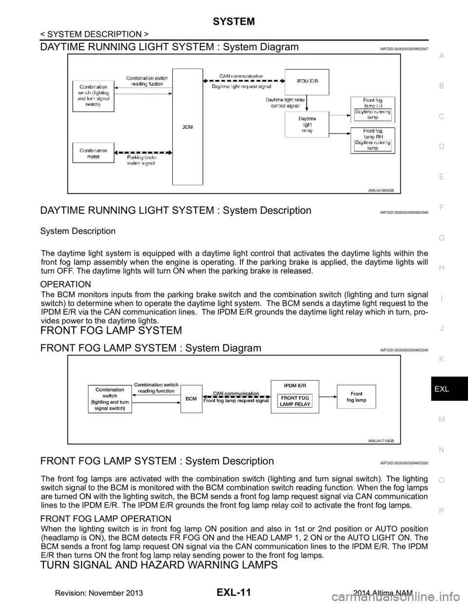
DAYTIME RUNNING LIGHT SY STEM : System DiagramINFOID:0000000009463547
DAYTIME RUNNING LIGHT SYST EM : System DescriptionINFOID:0000000009463548
System Description
The daytime light system is equipped with a daytime light control that activates the daytime lights within the
front fog lamp assembly when the engine is operating. If the parking brake is applied, the daytime lights will
turn OFF. The daytime lights will turn ON when the parking brake is released.
OPERATION
The BCM monitors inputs from the parking brake swit ch and the combination switch (lighting and turn signal
switch) to determine when to operate the daytime light s ystem. The BCM sends a daytime light request to the
IPDM E/R via the CAN communication lines. The IPDM E/ R grounds the daytime light relay which in turn, pro-
vides power to the daytime lights.
FRONT FOG LAMP SYSTEM
FRONT FOG LAMP SYSTEM : System DiagramINFOID:0000000009463549
FRONT FOG LAMP SYSTEM : System DescriptionINFOID:0000000009463550
The front fog lamps are activated with the combination switch (lighting and turn signal switch). The lighting
switch signal to the BCM is monitored with the BCM combination switch reading function. When the fog lamps
are turned ON with the lighting switch, the BCM sends a front fog lamp request signal via CAN communication
lines to the IPDM E/R. The IPDM E/R grounds the front fog lamp relay coil to activate the front fog lamps.
FRONT FOG LAMP OPERATION
When the lighting switch is in front fog lamp ON position and also in 1st or 2nd position or AUTO position
(headlamp is ON), the BCM detects FR FOG ON and the HEAD LAMP 1, 2 ON or the AUTO LIGHT ON. The
BCM sends a front fog lamp request ON signal via the CAN communication lines to the IPDM E/R. The IPDM
E/R then turns ON the front fog lamp re lay sending power to the front fog lamps.
TURN SIGNAL AND HAZARD WARNING LAMPS
AWLIA1965GB
AWLIA1719GB
Revision: November 20132014 Altima NAMRevision: November 20132014 Altima NAM
Page 2278 of 4801
EXL-12
< SYSTEM DESCRIPTION >
SYSTEM
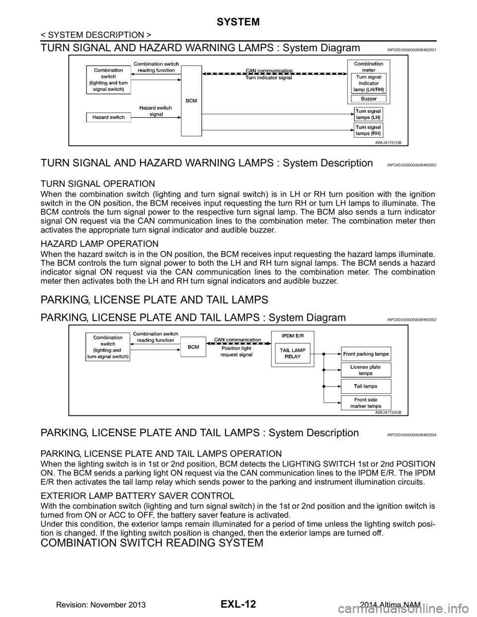
TURN SIGNAL AND HAZARD WARNI NG LAMPS : System Diagram
INFOID:0000000009463551
TURN SIGNAL AND HAZARD WARNING LAMPS : System DescriptionINFOID:0000000009463552
TURN SIGNAL OPERATION
When the combination switch (lighting and turn signal swit ch) is in LH or RH turn position with the ignition
switch in the ON position, the BCM receives input reques ting the turn RH or turn LH lamps to illuminate. The
BCM controls the turn signal power to the respective turn signal lamp. The BCM also sends a turn indicator
signal ON request via the CAN communication lines to the combination meter. The combination meter then
activates the appropriate turn signal indicator and audible buzzer.
HAZARD LAMP OPERATION
When the hazard switch is in the ON position, the BC M receives input requesting the hazard lamps illuminate.
The BCM controls the turn signal power to both the LH and RH turn signal lamps. The BCM sends a hazard
indicator signal ON request via the CAN communication lines to the combination meter. The combination
meter then activates both the LH and RH turn signal indicators and audible buzzer.
PARKING, LICENSE PLATE AND TAIL LAMPS
PARKING, LICENSE PLATE AND TAIL LAMPS : System DiagramINFOID:0000000009463553
PARKING, LICENSE PLATE AND TA IL LAMPS : System DescriptionINFOID:0000000009463554
PARKING, LICENSE PLATE AND TAIL LAMPS OPERATION
When the lighting switch is in 1st or 2nd position, BCM detects the LIGHTING SWITCH 1st or 2nd POSITION
ON. The BCM sends a parking light ON request via the CAN communication lines to the IPDM E/R. The IPDM
E/R then activates the tail lamp relay which sends power to the parking and instrument illumination circuits.
EXTERIOR LAMP BATTERY SAVER CONTROL
With the combination switch (lighting and turn signal switch) in the 1st or 2nd position and the ignition switch is
turned from ON or ACC to OFF, the battery saver feature is activated.
Under this condition, the exterior lamps remain illumi nated for a period of time unless the lighting switch posi-
tion is changed. If the lighting switch position is changed, then the exterior lamps are turned off.
COMBINATION SWITCH READING SYSTEM
AWLIA1721GB
AWLIA1723GB
Revision: November 20132014 Altima NAMRevision: November 20132014 Altima NAM
Page 2290 of 4801

EXL-24
< SYSTEM DESCRIPTION >
DIAGNOSIS SYSTEM (IPDM E/R)
APPLICATION ITEM
CONSULT performs the following functions via CAN communication with IPDM E/R.
ECU IDENTIFICATION
The IPDM E/R part number is displayed.
SELF DIAGNOSTIC RESULT
Refer to PCS-20, "DTC Index".
DATA MONITOR
Direct Diagnostic Mode Description
Ecu Identification The IPDM E/R part number is displayed.
Self Diagnostic Result The IPDM E/R self diagnostic results are displayed.
Data Monitor The IPDM E/R input/output data is displayed in real time.
Active Test The IPDM E/R activates outputs to test components.
CAN Diag Support Mntr The result of transmit/receive diagnosis of CAN communication is displayed.
Monitor Item [Unit] Main
Signals Description
MOTOR FAN REQ [%] ×Indicates cooling fan speed signal received from ECM on CAN communication
line
AC COMP REQ [On/Off] ×Indicates A/C compressor request signal received from ECM on CAN commu-
nication line
TAIL&CLR REQ [On/Off] ×Indicates position light request signal received from BCM on CAN communica-
tion line
HL LO REQ [On/Off] ×Indicates low beam request signal received from BCM on CAN communication
line
HL HI REQ [On/Off] ×Indicates high beam request signal received from BCM on CAN communication
line
FR FOG REQ [On/Off] ×Indicates front fog light request signal received from BCM on CAN communica-
tion line
FR WIP REQ [Stop/1LOW/Low/Hi] ×Indicates front wiper request signal received from BCM on CAN communication
line
WIP AUTO STOP [STOP P/ACT P] ×Indicates condition of front wiper auto stop signal
WIP PROT [Off/BLOCK] ×Indicates condition of front wiper fail-safe operation
IGN RLY1 -REQ [On/Off] Indicates ignition switch ON signal received from BCM on CAN communication
line
IGN RLY [On/Off] ×Indicates condition of ignition relay
PUSH SW [On/Off] Indicates condition of push-button ignition switch
INTER/NP SW [On/Off] Indicates condition of CVT shift position
ST RLY CONT [On/Off] Indicates starter relay status signal received from BCM on CAN communication
line
IHBT RLY -REQ [On/Off] Indicates starter control relay signal received from BCM on CAN communication
line
ST/INHI RLY [Off/ ST /INHI] Indicates condition of starter relay and starter control relay
DETENT SW [On/Off] Indicates condition of CVT shift selector (park position switch)
DTRL REQ [Off] Indicates daytime light request signal received from BCM on CAN communica-
tion line
HOOD SW [On/Off] Indicates condition of hood switch
THFT HRN REQ [On/Off] Indicates theft warning horn request signal received from BCM on CAN commu-
nication line
Revision: November 20132014 Altima NAMRevision: November 20132014 Altima NAM
Page 2381 of 4801
EXTERIOR LIGHTING SYSTEM SYMPTOMSEXL-115
< SYMPTOM DIAGNOSIS >
C
D E
F
G H
I
J
K
M A
B
EXL
N
O P
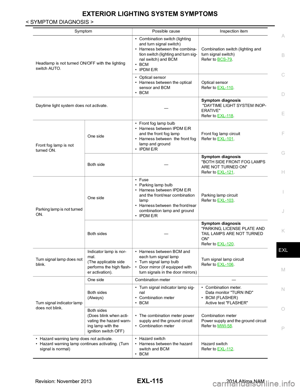
Headlamp is not turned ON/OFF with the lighting
switch AUTO. • Combination switch (lighting
and turn signal switch)
• Harness between the combina- tion switch (lighting and turn sig-
nal switch) and BCM
•BCM
• IPDM E/R Combination switch (lighting and
turn signal switch)
Refer to BCS-79.
• Optical sensor
• Harness between the optical
sensor and BCM
•BCM Optical sensor
Refer to EXL-110
.
Daytime light system does not activate. —Symptom diagnosis
"DAYTIME LIGHT SYSTEM INOP-
ERATIVE"
Refer to EXL-118
.
Front fog lamp is not
turned ON. One side
• Front fog lamp bulb
• Harness between IPDM E/R
and the front fog lamp
• Harness between the front fog lamp and ground
• IPDM E/R Front fog lamp circuit
Refer to EXL-101
.
Both side — Symptom diagnosis
"BOTH SIDE FRONT FOG LAMPS
ARE NOT TURNED ON"
Refer to EXL-121
.
Parking lamp is not turned
ON. One side•Fuse
• Parking lamp bulb
• Harness between IPDM E/R
and the front/rear combination
lamp
• Harness between the front/rear
combination lamp and ground
• IPDM E/R Parking lamp circuit
Refer to EXL-103
.
Both sides — Symptom diagnosis
"PARKING, LICENSE PLATE AND
TAIL LAMPS ARE NOT TURNED
ON"
Refer to EXL-120
.
Turn signal lamp does not
blink. Indicator lamp is nor-
mal.
(The applicable side
performs the high flash-
er activation). • Harness between BCM and
each turn signal lamp
• Turn signal lamp bulb
• Door mirror (if equipped with
turn signals in the door mirrors) Turn signal lamp circuit
Refer to EXL-106
.
Turn signal indicator lamp
does not blink. One side Combination meter —
Both sides
(Always) • Turn signal indicator lamp sig-
nal
• Combination meter
•BCM • Combination meter.
Data monitor "TURN IND"
• BCM (FLASHER) Active test "FLASHER"
Both sides
(Does blink when acti-
vating the hazard warn-
ing lamp with the
ignition switch OFF) • The combination meter power
supply and the ground circuit
• Combination meter Combination meter
Power supply and the ground circuit
Refer to MWI-58
.
• Hazard warning lamp does not activate.
• Hazard warning lamp continues activating. (Turn signal is normal) • Hazard switch
• Harness between the hazard switch and BCM
•BCM Hazard switch
Refer to EXL-112
.
Symptom Possible cause Inspection item
Revision: November 20132014 Altima NAMRevision: November 20132014 Altima NAM
Page 2397 of 4801
FRONT FOG LAMPEXL-131
< REMOVAL AND INSTALLATION >
C
D E
F
G H
I
J
K
M A
B
EXL
N
O P
FRONT FOG LAMP
Removal and InstallationINFOID:0000000009463627
REMOVAL
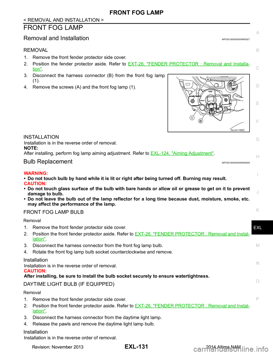
1. Remove the front fender protector side cover.
2. Position the fender protector aside. Refer to EXT-26, "FENDER PROTECTOR : Removal and Installa-
tion".
3. Disconnect the harness connector (B) from the front fog lamp (1).
4. Remove the screws (A) and the front fog lamp (1).
INSTALLATION
Installation is in the reverse order of removal.
NOTE:
After installing, perform fog lamp aiming adjustment. Refer to EXL-124, "Aiming Adjustment"
.
Bulb ReplacementINFOID:0000000009463628
WARNING:
• Do not touch bulb by hand while it is lit or right after being turned off. Burning may result.
CAUTION:
• Do not touch glass surface of the bulb with bare hand s or allow oil or grease to get on it to prevent
damage to bulb.
• Do not leave the bulb out of the lamp reflector fo r a long time because dust, moisture, smoke, etc.
may affect the performance of the lamp.
FRONT FOG LAMP BULB
Removal
1. Remove the front fender protector side cover.
2. Position the front fender pr otector aside. Refer to EXT-26, "FENDER PROTECTOR : Removal and Instal-
lation".
3. Disconnect the harness connector from the front fog lamp bulb.
4. Rotate the front fog lamp bulb socket counterclockwise and remove.
Installation
Installation is in the reverse order of removal.
CAUTION:
After installing, be sure to install the bulb socket securely to ensure watertightness.
DAYTIME LIGHT BULB (IF EQUIPPED)
Removal
1. Remove the front fender protector side cover.
2. Position the front fender pr otector aside. Refer to EXT-26, "FENDER PROTECTOR : Removal and Instal-
lation".
3. Disconnect the harness connector from the daytime light lamp.
4. Release the pawls and remove the daytime light lamp bulb.
Installation
Installation is in the reverse order of removal.
ALLIA1148ZZ
Revision: November 20132014 Altima NAMRevision: November 20132014 Altima NAM
Page 2523 of 4801
FSU-22
< UNIT DISASSEMBLY AND ASSEMBLY >
FRONT COIL SPRING AND STRUT
UNIT DISASSEMBLY AND ASSEMBLY
FRONT COIL SPRING AND STRUT
Disassembly and AssemblyINFOID:0000000009460638
DISASSEMBLY
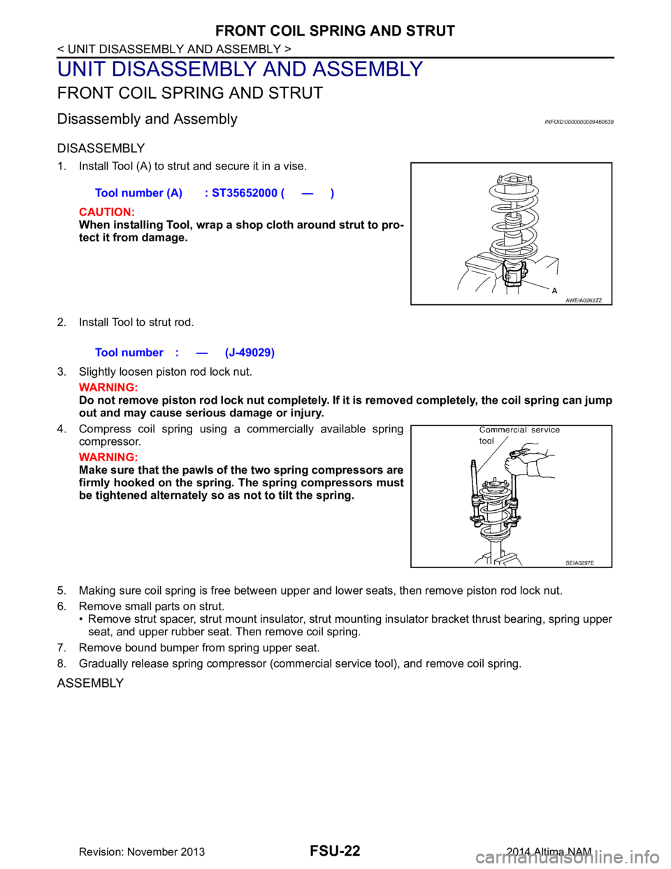
1. Install Tool (A) to strut and secure it in a vise.CAUTION:
When installing Tool, wrap a sh op cloth around strut to pro-
tect it from damage.
2. Install Tool to strut rod.
3. Slightly loosen piston rod lock nut. WARNING:
Do not remove piston rod lock nut completely. If it is removed completely, the coil spring can jump
out and may cause serious damage or injury.
4. Compress coil spring using a commercially available spring compressor.
WARNING:
Make sure that the pawls of the two spring compressors are
firmly hooked on the spring. The spring compressors must
be tightened alternately so as not to tilt the spring.
5. Making sure coil spring is free between upper and lower seats, then remove piston rod lock nut.
6. Remove small parts on strut. • Remove strut spacer, strut mount insulator, strut mounting insulator bracket thrust bearing, spring upper
seat, and upper rubber seat. Then remove coil spring.
7. Remove bound bumper from spring upper seat.
8. Gradually release spring compressor (commercial service tool), and remove coil spring.
ASSEMBLY
Tool number (A) : ST35652000 ( — )
AWEIA0262ZZ
Tool number : — (J-49029)
SEIA0297E
Revision: November 20132014 Altima NAM
Page 2543 of 4801

ABBREVIATIONSGI-15
< HOW TO USE THIS MANUAL >
C
D E
F
G H
I
J
K L
M B
GI
N
O P
I
K
L
M
N
O
ABBREVIATION DESCRIPTION I/M Inspection and maintenanceIA Intake air
IAC Idle air control IAT Intake air temperature
IBA Intelligent brake assist IC Ignition control
ICC Intelligent cruise control
ICM Ignition control module
IPDM E/R Intelligent power distribution module engine room ISC Idle speed controlISS Input shaft speed ITS Information technology suite
ABBREVIATION DESCRIPTION KS Knock sensor
ABBREVIATION DESCRIPTION LBC Li-ion battery controller
LCD Liquid crystal display
LCU Local control unit LDP Lane departure prevention
LDW Lane departure warning LED Light emitting diode LH Left-hand
LIN Local interconnect network
ABBREVIATION DESCRIPTION M/T Manual transaxle/transmission
MAF Mass airflow
MAP Manifold absolute pressure
MDU Multi display unit MI Malfunction indicator
MIL Malfunction indicator lamp
MOD Moving object detection
ABBREVIATION DESCRIPTION NOX Nitrogen oxides
ABBREVIATION DESCRIPTION O2 Oxygen
O2S Oxygen sensor
OBD On board diagnostic OC Oxidation catalytic converter
OD Overdrive
Revision: November 20132014 Altima NAMRevision: November 20132014 Altima NAM
Page 2628 of 4801
HA-22
< PERIODIC MAINTENANCE >
REFRIGERANT
4. Press UV lamp switch (5) and check A/C system for refrigerant leakage. (Where refrigerant leakage
occurs, fluorescent leak detec tion dye appears in green color.)
WARNING:
Do not look directly into UV lamp light source.
NOTE:
• For continuous operating time of UV lamp, follow the manufacturer operating instructions.
• Illuminate piping joints from different angles using UV lamp and check that there is no leakage.
• Use a mirror in area that is difficult to see to check refrigerant leakage.
• Refrigerant leakage from evaporator can be detected by soaking cotton swab or a similar material with
drain hose water and illuminating it using UV lamp.
• Dust, dirt and packing materials adhesive used for condenser, evaporator, and other locations may fluo- resce. Be careful not to misidentify leakage.
5. Repair or replace parts where refrigerant leakage occurs and wipe off fluorescent leak detection dye. NOTE:
Completely wipe off fluorescent leak detection dy e from gaps between parts, screw threads, and others
using a cotton swab or similar materials.
6. Use a UV lamp to check that no fluorescent leak detection dye remains after finishing work.
WARNING:
Do not look directly into UV lamp light source.
NOTE:
• For continuous operating time of UV lamp, follow the manufacturer operating instructions.
• Dust, dirt, and packing materials adhesive used for condenser, evaporator, and other locations may flu-
oresce. Be careful not to misidentify leakage.
CHECK REFRIGERANT LEAKAGE USING ELECTRICAL LEAK DETECTOR
WARNING:
Do not check refrigerant leakage while the engine is running.
CAUTION:
Be careful of the following it ems so that inaccurate checks or misidentifications are avoided.
• Do not allow refrigerant vapor, shop chemical vapor s, cigarette smoke or others around the vehicle.
• Always check refrigerant leakage in a low air flow en vironment so that refrigerant may not disperse
when leakage occurs.
1. Stop the engine.
2. Connect recovery/recycling/recharging equipment or manifold gauge set (J-39183-C) to A/C service
valve.
3. Check that A/C refrigerant pressure is 345 kPa (3.52 kg/cm
2, 50 psi) or more when temperature is 16 °C
(61 °F) or more. When pressure is lower than the specif ied value, recycle refrigerant completely and fill
refrigerant to the specified level.
NOTE:
Leakages may not be detected if A/C refrigerant pressure is 345 kPa (3.52 kg/cm
2, 50 psi) or less when
temperature is less than 16 °C (61 °F).
4. Clean area where refrigerant leakage check is performed and check refrigerant leakage along all surfaces of pipe connections and A/C system components us ing electrical leak detector (J-41995) probe.
CAUTION:
• Continue checking when a leakag e is found. Always continue and complete checking along all
pipe connections and A/C system components for additional leakage.
• When a leakage is detected, clean leakage area using compressed air and check again.
• When checking leakage of cooling unit inside, always clean inside of drain hose so that the
probe surface may not be exposed to water or dirt.
NOTE:
• Always check leakage starting from high-pressure side and continue to low-pressure side.
• When checking leakage of cooling unit inside, operate bl ower fan motor for 15 minutes or more at the
maximum fan speed while the engine is stopped, and then in sert electrical leak detector probe into drain
hose and hold for 10 minutes or more.
• When disconnecting shut-off valve that is connected to A/C service valve, always evacuate remaining
refrigerant so that misidentification can be avoided.
5. Repair or replace parts where refrigerant leak age is detected. (Leakage is detected but leakage area is
unknown.)
Revision: November 20132014 Altima NAM