2014 NISSAN TEANA warning light
[x] Cancel search: warning lightPage 3276 of 4801

MWI
DIAGNOSIS SYSTEM (METER)MWI-21
< SYSTEM DESCRIPTION >
C
D E
F
G H
I
J
K L
M B
A
O PSPECIAL FUNCTION
Special menu
W/L ON HISTORY
• “W/L ON HISTORY” indicates the “TIME” when the warning/ indicator lamp is turned on.
• The “TIME” above is:
- 0: The condition that the warning/indicator lamp has been turned on 1 or more times after starting the engine
and waiting for 30 seconds.
- 1 - 39: The number of times the engi ne was restarted after the 0 condition.
- NO W/L ON HISTORY: No warning/indicator lamp history is stored.
NOTE:
• W/L ON HISTORY is not stored for approximately 30 seconds after the engine starts.
• Brake warning lamp does not store any history when the parking brake is applied or the brake fluid level gets
low.
LDW IND
[ON/OFF] Displays [ON/OFF] condition of LDW warning indicator message in the informa-
tion display.
TPMS MALF
[ON/OFF] Displays [ON/OFF] condition of TPMS warning indicator.
Display item [Unit]
MAIN
SIGNALS Description
Display item Description
W/L ON HISTORY Lighting history of warning lamp and indicator lamp can be checked.
Revision: November 20132014 Altima NAMRevision: November 20132014 Altima NAM
Page 3277 of 4801

MWI-22
< ECU DIAGNOSIS INFORMATION >
COMBINATION METER
ECU DIAGNOSIS INFORMATION
COMBINATION METER
Reference ValueINFOID:0000000009461694
VALUES ON THE DIAGNOSIS TOOL
Monitor Item Condition Value/Status
SPEED METER
[mph or km/h] Ignition switch ON While driving
Input value of vehicle speed signal
(CAN communication signal)
SPEED OUTPUT
[mph or km/h] Ignition switch ON While driving Output value of vehicle speed sig-
nal (CAN communication signal)
ODO OUTPUT
[mph or km/h] Ignition switch ON — Output value of odometer signal
(CAN communication signal)
TACHO METER
[rpm] Ignition switch ON Engine running
Input value of engine speed signal
(CAN communication signal)
FUEL METER
[L] Ignition switch ON — Input value of fuel level sensor sig-
nal
W TEMP METER
[ ° F] or [ °C] Ignition switch ON — Input value of engine coolant tem-
perature signal (CAN communica-
tion signal)
ABS W/L Ignition switch ON ABS warning lamp ON On
ABS warning lamp OFF Off
VDC/TCS IND Ignition switch ON VDC OFF indica
tor lamp ON On
VDC OFF indicato r lamp OFF Off
SLIP IND Ignition switch ON VDC warning lamp ON On
VDC warning lamp OFF Off
BRAKE W/L Ignition switch ON Brake warning lamp ON On
Brake warning lamp OFF Off
DOOR W/L Ignition switch ON Door open warning ON On
Other than the above Off
TRUNK/GLAS-H Ignition switch ON Trunk open warning ON On
Trunk open warning OFF Off
HI-BEAM IND Ignition switch ON High beam indicator lamp ON On
High beam indicator lamp OFF Off
TURN IND Ignition switch ON Turn signal indicator lamp ON On
Turn signal indicator lamp OFF Off
LIGHT IND Ignition switch ON Tail lamp indicator lamp ON On
Tail lamp indicator lamp OFF Off
FR FOG IND Ignition switch ON Front fog lamp indicator lamp ON On
Front fog lamp indicator lamp OFF Off
OIL W/L Ignition switch ON Oil pressure warning On
Oil pressure warning Off
MIL Ignition switch ON Malfunction indicator lamp ON On
Malfunction indicator lamp OFF Off
CRUISE IND Ignition switch ON CRUISE indicator ON On
CRUISE indicator OFF Off
Revision: November 20132014 Altima NAMRevision: November 20132014 Altima NAM
Page 3359 of 4801
![NISSAN TEANA 2014 Service Manual
PCS-10
< SYSTEM DESCRIPTION >[IPDM E/R]
DIAGNOSIS SYSTEM (IPDM E/R)
APPLICATION ITEM
CONSULT performs the following functions
via CAN communication with IPDM E/R.
ECU IDENTIFICATION
The IPDM E/R par NISSAN TEANA 2014 Service Manual
PCS-10
< SYSTEM DESCRIPTION >[IPDM E/R]
DIAGNOSIS SYSTEM (IPDM E/R)
APPLICATION ITEM
CONSULT performs the following functions
via CAN communication with IPDM E/R.
ECU IDENTIFICATION
The IPDM E/R par](/manual-img/5/57390/w960_57390-3358.png)
PCS-10
< SYSTEM DESCRIPTION >[IPDM E/R]
DIAGNOSIS SYSTEM (IPDM E/R)
APPLICATION ITEM
CONSULT performs the following functions
via CAN communication with IPDM E/R.
ECU IDENTIFICATION
The IPDM E/R part number is displayed.
SELF DIAGNOSTIC RESULT
Refer to PCS-20, "DTC Index".
DATA MONITOR
Direct Diagnostic Mode Description
Ecu Identification The IPDM E/R part number is displayed.
Self Diagnostic Result The IPDM E/R self diagnostic results are displayed.
Data Monitor The IPDM E/R input/output data is displayed in real time.
Active Test The IPDM E/R activates outputs to test components.
CAN Diag Support Mntr The result of transmit/receive diagnosis of CAN communication is displayed.
Monitor Item [Unit] Main
Signals Description
MOTOR FAN REQ [%] ×Indicates cooling fan speed signal received from ECM on CAN communication
line
AC COMP REQ [On/Off] ×Indicates A/C compressor request signal received from ECM on CAN commu-
nication line
TAIL&CLR REQ [On/Off] ×Indicates position light request signal received from BCM on CAN communica-
tion line
HL LO REQ [On/Off] ×Indicates low beam request signal received from BCM on CAN communication
line
HL HI REQ [On/Off] ×Indicates high beam request signal received from BCM on CAN communication
line
FR FOG REQ [On/Off] ×Indicates front fog light request signal received from BCM on CAN communica-
tion line
FR WIP REQ [Stop/1LOW/Low/Hi] ×Indicates front wiper request signal received from BCM on CAN communication
line
WIP AUTO STOP [STOP P/ACT P] ×Indicates condition of front wiper auto stop signal
WIP PROT [Off/BLOCK] ×Indicates condition of front wiper fail-safe operation
IGN RLY1 -REQ [On/Off] Indicates ignition switch ON signal received from BCM on CAN communication
line
IGN RLY [On/Off] ×Indicates condition of ignition relay
PUSH SW [On/Off] Indicates condition of push-button ignition switch
INTER/NP SW [On/Off] Indicates condition of CVT shift position
ST RLY CONT [On/Off] Indicates starter relay status signal received from BCM on CAN communication
line
IHBT RLY -REQ [On/Off] Indicates starter control relay signal received from BCM on CAN communication
line
ST/INHI RLY [Off/ ST /INHI] Indicates condition of starter relay and starter control relay
DETENT SW [On/Off] Indicates condition of CVT shift selector (park position switch)
DTRL REQ [Off] Indicates daytime light request signal received from BCM on CAN communica-
tion line
HOOD SW [On/Off] Indicates condition of hood switch
THFT HRN REQ [On/Off] Indicates theft warning horn request signal received from BCM on CAN commu-
nication line
Revision: November 20132014 Altima NAMRevision: November 20132014 Altima NAM
Page 3852 of 4801
DIAGNOSIS SYSTEM (IPDM E/R)SEC-27
< SYSTEM DESCRIPTION >
C
D E
F
G H
I
J
L
M A
B
SEC
N
O P
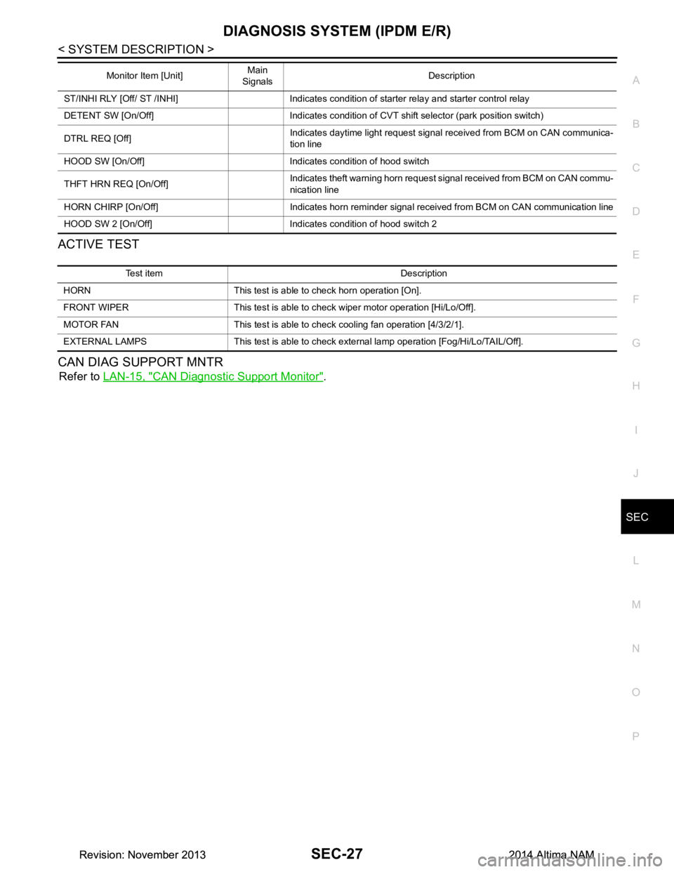
ACTIVE TEST
CAN DIAG SUPPORT MNTR
Refer to LAN-15, "CAN Diagnostic Support Monitor".
ST/INHI RLY [Off/ ST /INHI] Indicates condition of starter relay and starter control relay
DETENT SW [On/Off] Indicates condition of CVT shift selector (park position switch)
DTRL REQ [Off] Indicates daytime light request signal received from BCM on CAN communica-
tion line
HOOD SW [On/Off] Indicates condition of hood switch
THFT HRN REQ [On/Off] Indicates theft warning horn request signal received from BCM on CAN commu-
nication line
HORN CHIRP [On/Off] Indicates horn reminder signal received from BCM on CAN communication line
HOOD SW 2 [On/Off] Indicates condition of hood switch 2 Monitor Item [Unit]
Main
Signals Description
Test item Description
HORN This test is able to check horn operation [On].
FRONT WIPER This test is able to check wiper motor operation [Hi/Lo/Off].
MOTOR FAN This test is able to check cooling fan operation [4/3/2/1].
EXTERNAL LAMPS This test is able to check external lamp operation [Fog/Hi/Lo/TAIL/Off].
Revision: November 20132014 Altima NAMRevision: November 20132014 Altima NAM
Page 4010 of 4801
DIAGNOSIS SYSTEM (AIR BAG)SRC-17
< SYSTEM DESCRIPTION >
C
D E
F
G
I
J
K L
M A
B
SRC
N
O P
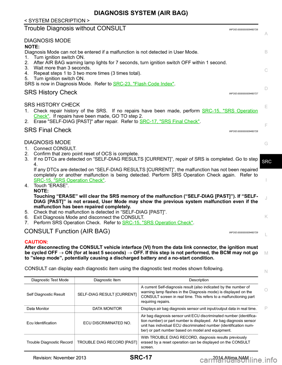
Trouble Diagnosis without CONSULTINFOID:0000000009460726
DIAGNOSIS MODE
NOTE:
Diagnosis Mode can not be entered if a malfunction is not detected in User Mode.
1. Turn ignition switch ON.
2. After AIR BAG warning lamp lights for 7 seconds, turn ignition switch OFF within 1 second.
3. Wait more than 3 seconds.
4. Repeat steps 1 to 3 two more times (3 times total).
5. Turn ignition switch ON.
SRS is now in Diagnosis Mode. Refer to SRC-23, "Flash Code Index"
.
SRS History CheckINFOID:0000000009460727
SRS HISTORY CHECK
1. Check repair history of the SRS. If no repairs have been made, perform SRC-15, "SRS Operation
Check". If repairs have been made, GO TO step 2.
2. Erase "SELF-DIAG [PAST]" after repair. Refer to SRC-17, "SRS Final Check"
.
SRS Final CheckINFOID:0000000009460728
DIAGNOSIS MODE
1. Connect CONSULT.
2. Confirm that zero point reset of OCS is complete.
3. If no DTCs are detected on “SELF- DIAG RESULTS [CURRENT]”, repair of SRS is completed. Go to step
4.
If any DTCs are detected on “SEL F-DIAG RESULTS [CURRENT]”, t he malfunction has not been repaired
completely or another malfunction is being detected. Perform SRS Operation Check again. Refer to
SRC-15, "SRS Operation Check"
.
4. Touch “ERASE”. NOTE:
Touching “ERASE” will clear the SRS memory of the malfunction (“SELF-DIAG [PAST]”). If “SELF-
DIAG [PAST]” is not erased, User Mode may s how the previous system malfunction even if the
malfunction has been repaired completely.
5. Check that no malfunction is detected in “SELF-DIAG [PAST]”.
6. Exit Diagnosis Mode and disconnect the CONSULT.
7. Perform SRS Operation Check. Refer to SRC-15, "SRS Operation Check"
.
CONSULT Function (AIR BAG)INFOID:0000000009460729
CAUTION:
After disconnecting the CONSULT vehicle interface (VI) from the data link connector, the ignition must
be cycled OFF → ON (for at least 5 seconds) → OFF. If this step is not performed, the BCM may not go
to ”sleep mode”, potentiall y causing a discharged battery and a no-start condition.
CONSULT can display each diagnostic item using the diagnostic test modes shown following.
Diagnostic Test Mode Diagnostic Item Description
Self Diagnostic Result SEL F-DIAG RESULT [CURRENT]A current Self-diagnosis result (also indicated by the number of
warning lamp flashes in the Diagnosis mode) is displayed on the
CONSULT screen in real time. This refers to a malfunctioning part
requiring repairs.
Data Monitor DATA MONITOR Displays air bag diagnosis sensor unit input/output data in real time.
Ecu Identification ECU DISCRIMINATED NO. Air bag diagnosis sensor unit ECU discriminated number (identifica-
tion number) or part number is displayed. Air bag diagnosis sensor
unit has individual ECU discriminated number (identification num-
ber) or part number based on model and equipment.
Trouble Diagnostic Record TROUBLE DIAG RECORD [PAST] With TROUBLE DIAG RECORD, diagnosis results previously
erased by a reset operation can be displayed on the CONSULT
screen.
Revision: November 20132014 Altima NAMRevision: November 20132014 Altima NAM
Page 4090 of 4801
B1428 SEAT BELT BUCKLE SWITCH LHSRC-97
< DTC/CIRCUIT DIAGNOSIS >
C
D E
F
G
I
J
K L
M A
B
SRC
N
O P
YES >> Refer to SRC-97, "Diagnosis Procedure".
NO >> Inspection End.
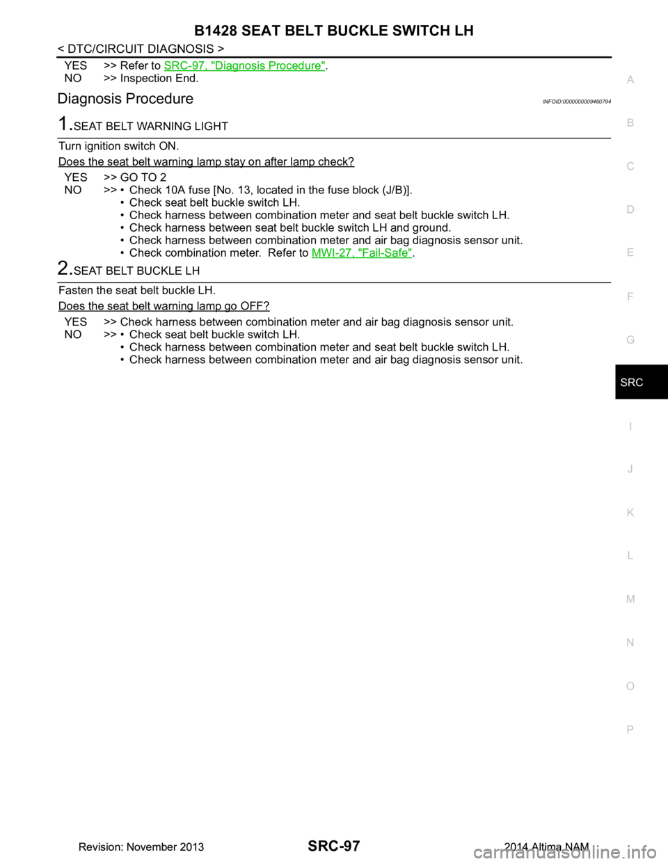
Diagnosis ProcedureINFOID:0000000009460794
1.SEAT BELT WARNING LIGHT
Turn ignition switch ON.
Does the seat belt warning lamp stay on after lamp check?
YES >> GO TO 2
NO >> • Check 10A fuse [No. 13, loca ted in the fuse block (J/B)].
• Check seat belt buckle switch LH.
• Check harness between combination meter and seat belt buckle switch LH.
• Check harness between seat belt buckle switch LH and ground.
• Check harness between combination meter and air bag diagnosis sensor unit.
• Check combination meter. Refer to MWI-27, "Fail-Safe"
.
2.SEAT BELT BUCKLE LH
Fasten the seat belt buckle LH.
Does the seat belt warning lamp go OFF?
YES >> Check harness between combination meter and air bag diagnosis sensor unit.
NO >> • Check seat belt buckle switch LH. • Check harness between combination meter and seat belt buckle switch LH.
• Check harness between combination meter and air bag diagnosis sensor unit.
Revision: November 20132014 Altima NAMRevision: November 20132014 Altima NAM
Page 4092 of 4801
B1429 SEAT BELT BUCKLE SWITCH RHSRC-99
< DTC/CIRCUIT DIAGNOSIS >
C
D E
F
G
I
J
K L
M A
B
SRC
N
O P
YES >> Refer to SRC-99, "Diagnosis Procedure".
NO >> Inspection End.
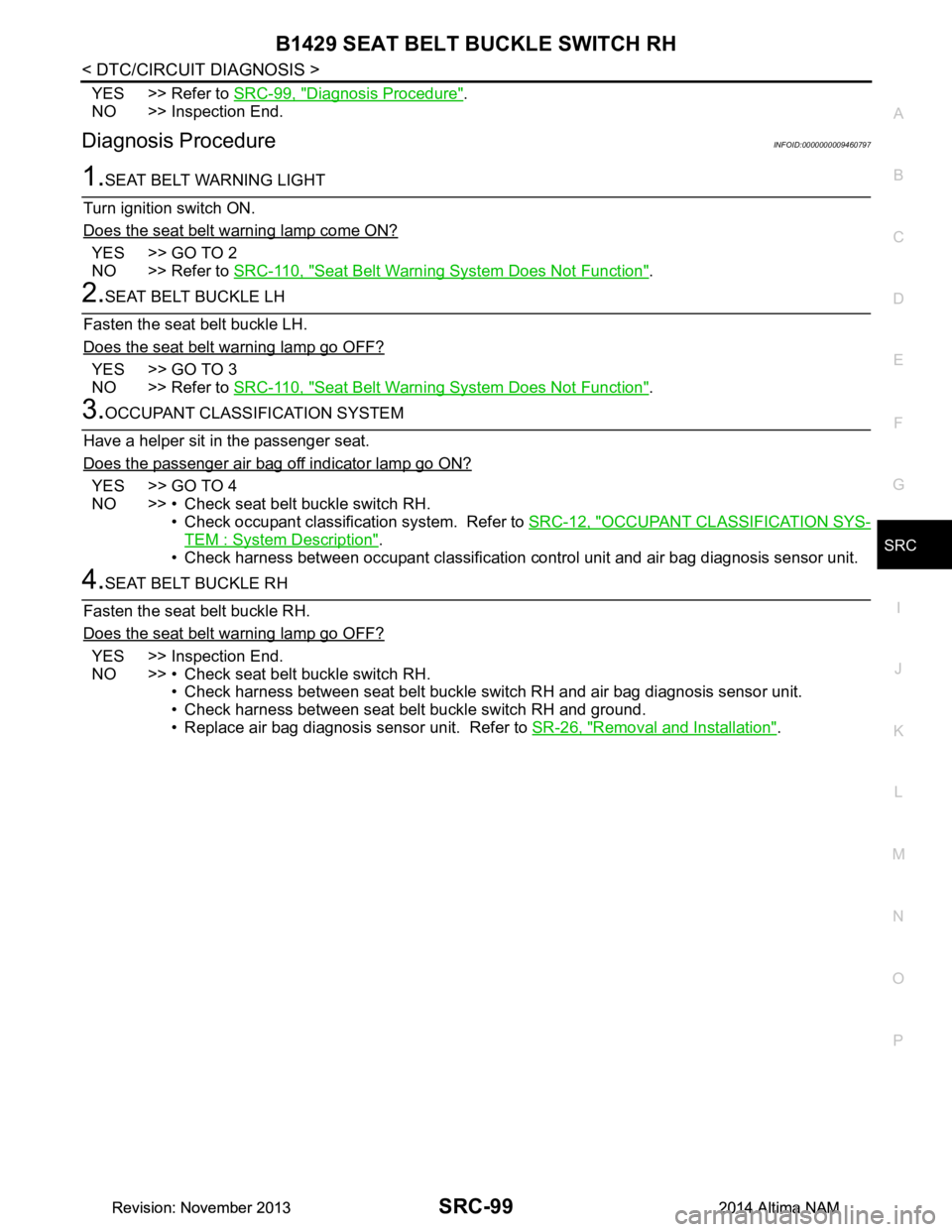
Diagnosis ProcedureINFOID:0000000009460797
1.SEAT BELT WARNING LIGHT
Turn ignition switch ON.
Does the seat belt warning lamp come ON?
YES >> GO TO 2
NO >> Refer to SRC-110, "Seat Belt Warni ng System Does Not Function"
.
2.SEAT BELT BUCKLE LH
Fasten the seat belt buckle LH.
Does the seat belt warning lamp go OFF?
YES >> GO TO 3
NO >> Refer to SRC-110, "Seat Belt Warni ng System Does Not Function"
.
3.OCCUPANT CLASSIFICATION SYSTEM
Have a helper sit in the passenger seat.
Does the passenger air bag off indicator lamp go ON?
YES >> GO TO 4
NO >> • Check seat belt buckle switch RH.
• Check occupant classification system. Refer to SRC-12, "OCCUPANT CLASSIFICATION SYS-
TEM : System Description".
• Check harness between occupant classification control unit and air bag diagnosis sensor unit.
4.SEAT BELT BUCKLE RH
Fasten the seat belt buckle RH.
Does the seat belt warning lamp go OFF?
YES >> Inspection End.
NO >> • Check seat belt buckle switch RH. • Check harness between seat belt buckle switch RH and air bag diagnosis sensor unit.
• Check harness between seat belt buckle switch RH and ground.
• Replace air bag diagnosis sensor unit. Refer to SR-26, "Removal and Installation"
.
Revision: November 20132014 Altima NAMRevision: November 20132014 Altima NAM
Page 4103 of 4801
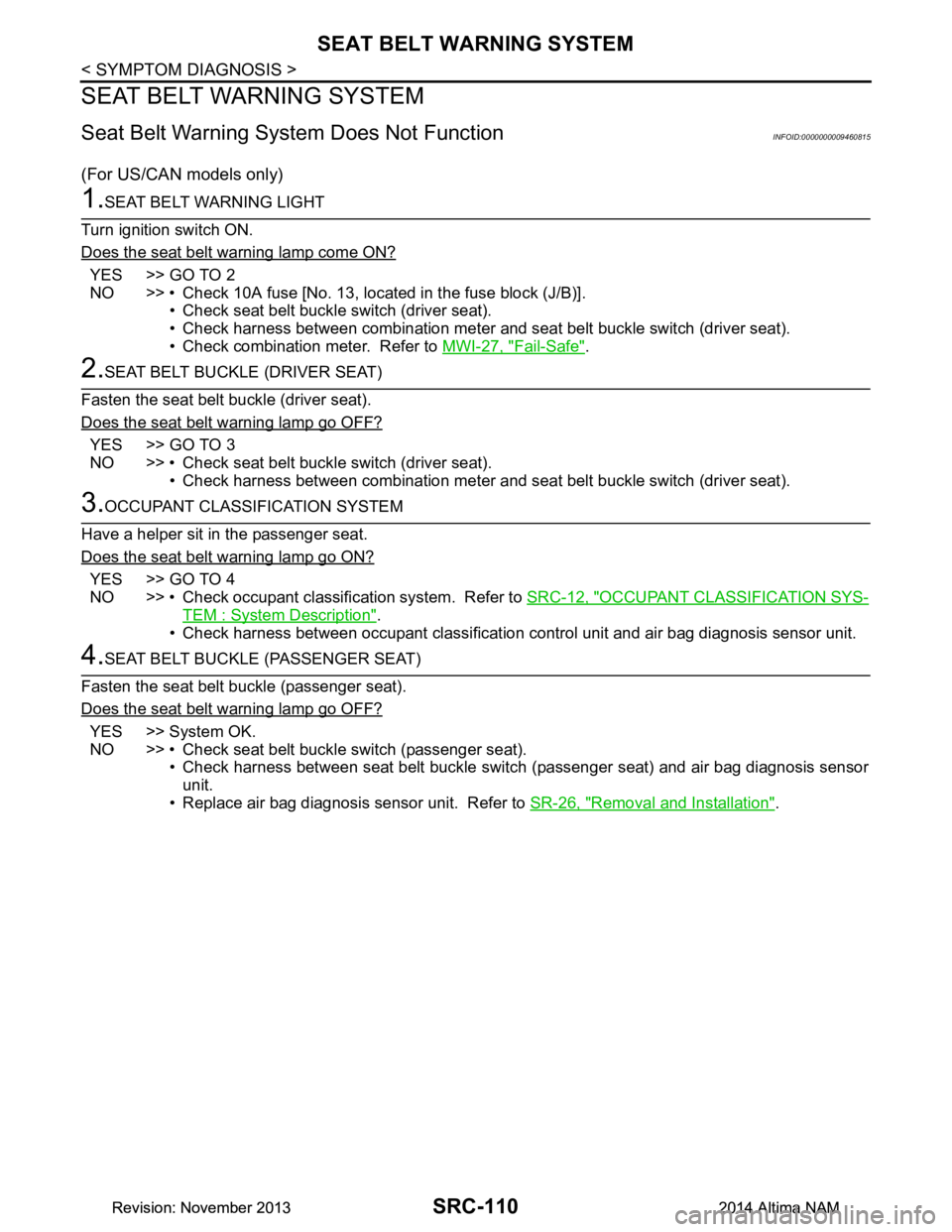
SRC-110
< SYMPTOM DIAGNOSIS >
SEAT BELT WARNING SYSTEM
SEAT BELT WARNING SYSTEM
Seat Belt Warning System Does Not FunctionINFOID:0000000009460815
(For US/CAN models only)
1.SEAT BELT WARNING LIGHT
Turn ignition switch ON.
Does the seat belt warning lamp come ON?
YES >> GO TO 2
NO >> • Check 10A fuse [No. 13, located in the fuse block (J/B)].
• Check seat belt buckle switch (driver seat).
• Check harness between combination meter and seat belt buckle switch (driver seat).
• Check combination meter. Refer to MWI-27, "Fail-Safe"
.
2.SEAT BELT BUCKLE (DRIVER SEAT)
Fasten the seat belt buckle (driver seat).
Does the seat belt warning lamp go OFF?
YES >> GO TO 3
NO >> • Check seat belt buckle switch (driver seat). • Check harness between combination meter and seat belt buckle switch (driver seat).
3.OCCUPANT CLASSIFICATION SYSTEM
Have a helper sit in the passenger seat.
Does the seat belt warning lamp go ON?
YES >> GO TO 4
NO >> • Check occupant classification system. Refer to SRC-12, "OCCUPANT CLASSIFICATION SYS-
TEM : System Description".
• Check harness between occupant classification control unit and air bag diagnosis sensor unit.
4.SEAT BELT BUCKLE (PASSENGER SEAT)
Fasten the seat belt buckle (passenger seat).
Does the seat belt warning lamp go OFF?
YES >> System OK.
NO >> • Check seat belt buckle switch (passenger seat). • Check harness between seat belt buckle switch (passenger seat) and air bag diagnosis sensorunit.
• Replace air bag diagnosis sensor unit. Refer to SR-26, "Removal and Installation"
.
Revision: November 20132014 Altima NAMRevision: November 20132014 Altima NAM