2014 NISSAN TEANA warning light
[x] Cancel search: warning lightPage 4155 of 4801

STC-4
< SYSTEM DESCRIPTION >
COMPONENT PARTS
SYSTEM DESCRIPTION
COMPONENT PARTS
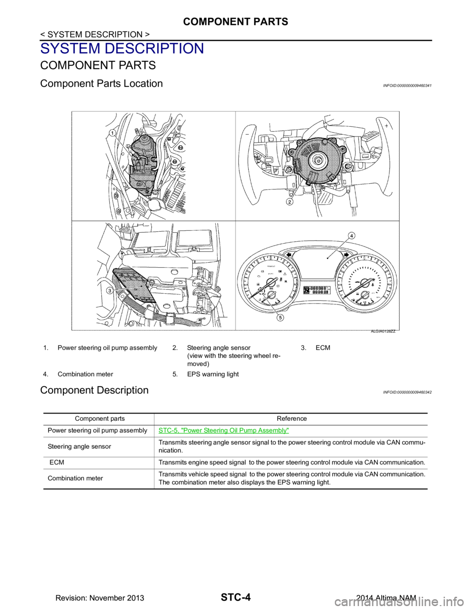
Component Parts LocationINFOID:0000000009460341
Component DescriptionINFOID:0000000009460342
1. Power steering oil pump assembly 2. Steering angle sensor(view with the steering wheel re-
moved) 3. ECM
4. Combination meter 5. EPS warning light
ALGIA0128ZZ
Component parts Reference
Power steering oil pump assembly STC-5, "Power Steering Oil Pump Assembly"
Steering angle sensorTransmits steering angle sensor signal to the power steering control module via CAN commu-
nication.
ECM Transmits engine speed signal to the power steering control module via CAN communication.
Combination meter Transmits vehicle speed signal to the power steering control module via CAN communication.
The combination meter also di splays the EPS warning light.
Revision: November 20132014 Altima NAMRevision: November 20132014 Altima NAM
Page 4256 of 4801
![NISSAN TEANA 2014 Service Manual
DIAGNOSIS SYSTEM (TCM)TM-41
< SYSTEM DESCRIPTION > [CVT: RE0F10D]
C
EF
G H
I
J
K L
M A
B
TM
N
O P
DIAGNOSIS SYSTEM (TCM)
DIAGNOSIS DESCRIPTION
DIAGNOSIS DESCRIPTION : 1 Tr ip Detection Diagnosis and NISSAN TEANA 2014 Service Manual
DIAGNOSIS SYSTEM (TCM)TM-41
< SYSTEM DESCRIPTION > [CVT: RE0F10D]
C
EF
G H
I
J
K L
M A
B
TM
N
O P
DIAGNOSIS SYSTEM (TCM)
DIAGNOSIS DESCRIPTION
DIAGNOSIS DESCRIPTION : 1 Tr ip Detection Diagnosis and](/manual-img/5/57390/w960_57390-4255.png)
DIAGNOSIS SYSTEM (TCM)TM-41
< SYSTEM DESCRIPTION > [CVT: RE0F10D]
C
EF
G H
I
J
K L
M A
B
TM
N
O P
DIAGNOSIS SYSTEM (TCM)
DIAGNOSIS DESCRIPTION
DIAGNOSIS DESCRIPTION : 1 Tr ip Detection Diagnosis and 2 Trip Detection Diagno-
sis
INFOID:0000000009463996
NOTE:
“Start the engine and turn OFF the ignition switch after warm-up.” This is defined as 1 trip.
1 TRIP DETECTION DIAGNOSIS
When initial malfunction is detected, TCM memorize s DTC. In these diagnoses, some illuminate MIL and
some do not. Refer to TM-60, "DTC Index"
.
2 TRIP DETECTION DIAGNOSIS
When initial malfunction is detected, TCM memorizes DTC of the 1st trip. MIL does not light at this stage. <1
trip>
If the same malfunction is detected again in next drivi ng, TCM memorizes DTC. When DTC is memorized, MIL
lights. <2 trip>
“Trip” of the “2 trip detection diagnosis” indicates the driving mode that executes self-diagnosis during driving.
×: Check possible —: Check not possible
DIAGNOSIS DESCRIPTION : DTC and DTC of 1st TripINFOID:0000000009463997
2 TRIP DETECTION DIAGNOSIS THAT ILLUMINATES MIL
• The DTC number of the 1st trip is the same as the DTC number.
• When a malfunction is detected at the 1st trip, TCM memo rizes DTC of the 1st trip. MIL does not light at this
stage. If the same malfunction is not detected at t he 2nd trip (conforming to necessary driving conditions),
DTC at the 1st trip is erased from TCM. If the same malfunction is detected at the 2nd trip, TCM memorizes
DTC and MIL lights at the same time.
• The DTC of the 1st trip is specified in Service $01 of SAE J1979/ISO 15031-5. Since detection of DTC at the
1st trip does not illuminate MIL, warning for a problem is not given to a driver.
• For procedure to delete DTC and 1st trip DTC from TCM, refer to TM-43, "CONSULT Function"
.
• If DTC of the 1st trip is detected, it is necessary to check the cause according to the “Diagnosis flow”. Refer
to TM-77, "Flowchart of Trouble Diagnosis"
.
DIAGNOSIS DESCRIPTION : Malf unction Indicator Lamp (MIL)INFOID:0000000009463998
• TCM not only detects DTC, but also sends the MI L signal to ECM through CAN communication. ECM sends
the MIL signal to the combination meter through CAN communication according to the signal, and illumi-
nates MIL.
• For malfunction indicator lamp (MIL) description, refer to EC-74, "DIAGNOSIS DESCRIPTION : Malfunction
Indicator Lamp (MIL)".
DIAGNOSIS DESCRIPTION : Counter SystemINFOID:0000000009463999
RELATION BETWEEN DTC AT 1ST TRIP/DTC/MIL AND DRIVING CONDITIONS (FOR 2 TRIP DE-
TECTION DIAGNOSIS THAT ILLUMINATES MIL)
• When initial malfunction is detected, TCM memorizes DT C of the 1st trip. MIL does not light at this stage.
• If the same malfunction is detect ed at the 2nd trip, TCM memorizes DTC and MIL lights at the same time.
• Then, MIL goes after driving the vehicle for 3 tr ips under “Driving condition B” without malfunction.
• DTC is displayed until 40 trips of “Driving condition A” are satisfied without detecting the same malfunction.
DTC is erased when 40 trips are satisfied.
Item DTC at the 1st trip DTC MIL
Display at the 1st trip Display at the
2nd trip Display at the
1st trip Display at the
2nd trip Illumination at
the 1st trip Illumination at
the 2nd trip
1 trip detection diagnosis
(Refer to TM-60, "DTC Index"
) ——
×— ×—
2 trip detection diagnosis
(Refer to TM-60, "DTC Index"
) ×
—— ×— ×
Revision: November 20132014 Altima NAMRevision: November 20132014 Altima NAM
Page 4458 of 4801
![NISSAN TEANA 2014 Service Manual
DIAGNOSIS SYSTEM (TCM)TM-243
< SYSTEM DESCRIPTION > [CVT: RE0F10E]
C
EF
G H
I
J
K L
M A
B
TM
N
O P
DIAGNOSIS SYSTEM (TCM)
DIAGNOSIS DESCRIPTION
DIAGNOSIS DESCRIPTION : 1 Tr ip Detection Diagnosis an NISSAN TEANA 2014 Service Manual
DIAGNOSIS SYSTEM (TCM)TM-243
< SYSTEM DESCRIPTION > [CVT: RE0F10E]
C
EF
G H
I
J
K L
M A
B
TM
N
O P
DIAGNOSIS SYSTEM (TCM)
DIAGNOSIS DESCRIPTION
DIAGNOSIS DESCRIPTION : 1 Tr ip Detection Diagnosis an](/manual-img/5/57390/w960_57390-4457.png)
DIAGNOSIS SYSTEM (TCM)TM-243
< SYSTEM DESCRIPTION > [CVT: RE0F10E]
C
EF
G H
I
J
K L
M A
B
TM
N
O P
DIAGNOSIS SYSTEM (TCM)
DIAGNOSIS DESCRIPTION
DIAGNOSIS DESCRIPTION : 1 Tr ip Detection Diagnosis and 2 Trip Detection Diagno-
sis
INFOID:0000000009464213
NOTE:
“Start the engine and turn OFF the ignition switch after warm-up.” This is defined as 1 trip.
1 TRIP DETECTION DIAGNOSIS
When initial malfunction is detected, TCM memorize s DTC. In these diagnoses, some illuminate MIL and
some do not. Refer to TM-263, "DTC Index"
.
2 TRIP DETECTION DIAGNOSIS
When initial malfunction is detected, TCM memorizes DTC of the 1st trip. MIL does not light at this stage. <1
trip>
If the same malfunction is detected again in next drivi ng, TCM memorizes DTC. When DTC is memorized, MIL
lights. <2 trip>
“Trip” of the “2 trip detection diagnosis” indicates the driving mode that executes self-diagnosis during driving.
×: Check possible —: Check not possible
DIAGNOSIS DESCRIPTION : DTC and DTC of 1st TripINFOID:0000000009464214
2 TRIP DETECTION DIAGNOSIS THAT ILLUMINATES MIL
• The DTC number of the 1st trip is the same as the DTC number.
• When a malfunction is detected at the 1st trip, TCM memo rizes DTC of the 1st trip. MIL does not light at this
stage. If the same malfunction is not detected at t he 2nd trip (conforming to necessary driving conditions),
DTC at the 1st trip is erased from TCM. If the same malfunction is detected at the 2nd trip, TCM memorizes
DTC and MIL lights at the same time.
• The DTC of the 1st trip is specified in Service $01 of SAE J1979/ISO 15031-5. Since detection of DTC at the
1st trip does not illuminate MIL, warning for a problem is not given to a driver.
• For procedure to delete DTC and 1st trip DTC from TCM, refer to TM-245, "CONSULT Function"
.
• If DTC of the 1st trip is detected, it is necessary to check the cause according to the “Diagnosis flow”. Refer
to TM-279, "Work Flow"
.
DIAGNOSIS DESCRIPTION : Malf unction Indicator Lamp (MIL)INFOID:0000000009464215
• TCM not only detects DTC, but also sends the MI L signal to ECM through CAN communication. ECM sends
the MIL signal to the combination meter through CAN communication according to the signal, and illumi-
nates MIL.
• For malfunction indicator lamp (MIL) description, refer to EC-598, "DIAGNOSIS DESCRIPTION : Malfunc-
tion Indicator Lamp (MIL)".
DIAGNOSIS DESCRIPTION : Counter SystemINFOID:0000000009464216
RELATION BETWEEN DTC AT 1ST TRIP/DTC/MIL AND DRIVING CONDITIONS (FOR 2 TRIP DE-
TECTION DIAGNOSIS THAT ILLUMINATES MIL)
• When initial malfunction is detected, TCM memorizes DT C of the 1st trip. MIL does not light at this stage.
• If the same malfunction is detect ed at the 2nd trip, TCM memorizes DTC and MIL lights at the same time.
• Then, MIL goes after driving the vehicle for 3 tr ips under “Driving condition B” without malfunction.
• DTC is displayed until 40 trips of “Driving condition A” are satisfied without detecting the same malfunction.
DTC is erased when 40 trips are satisfied.
Item DTC at the 1st trip DTC MIL
Display at the 1st trip Display at the
2nd trip Display at the
1st trip Display at the
2nd trip Illumination at
the 1st trip Illumination at
the 2nd trip
1 trip detection diagnosis
(Refer to TM-263, "DTC Index"
) ——
×— ×—
2 trip detection diagnosis
(Refer to TM-263, "DTC Index"
) ×
—— ×— ×
Revision: November 20132014 Altima NAMRevision: November 20132014 Altima NAM
Page 4643 of 4801

WCS
WCS-1
DRIVER INFORMATION & MULTIMEDIA
C
D E
F
G H
I
J
K L
M B
SECTION WCS
A
O P
CONTENTS
WARNING CHIME SYSTEM
PRECAUTION ................ ...............................3
PRECAUTIONS .............................................. .....3
Precaution for Supplemental Restraint System
(SRS) "AIR BAG" and "SEAT BELT PRE-TEN-
SIONER" ............................................................. ......
3
SYSTEM DESCRIPTION ..............................4
COMPONENT PARTS ................................... .....4
Component Parts Location .................................. ......4
Component Description .............................................4
SYSTEM ..............................................................6
WARNING CHIME SYSTEM .......................................6
WARNING CHIME SYSTEM : System Diagram . ......6
WARNING CHIME SYSTEM : System Description
......
6
LIGHT REMINDER WARNING CHIME ................. ......6
LIGHT REMINDER WARNING CHIME : System
Diagram ............................................................... ......
6
LIGHT REMINDER WARNING CHIME : System
Description .......................................................... ......
6
SEAT BELT WARNING CHIME ............................ ......7
SEAT BELT WARNING CHIME : System Diagram
......
7
SEAT BELT WARNING CHIME : System Descrip-
tion ...................................................................... ......
7
PARKING BRAKE RELEASE WARNING CHIME ......7
PARKING BRAKE RELEASE WARNING CHIME
: System Diagram ................................................ ......
7
PARKING BRAKE RELEASE WARNING CHIME
: System Description ........................................... ......
7
DIAGNOSIS SYSTEM (METER) .........................9
Description .......................................................... ......9
CONSULT Function (METER/M&A) .........................9
DIAGNOSIS SYSTEM (BCM) ............................13
COMMON ITEM ..................................................... ....13
COMMON ITEM : CONSULT Function (BCM -
COMMON ITEM) ................................................. ....
13
BUZZER ................................................................. ....14
BUZZER : CONSULT Function (BCM - BUZZER) ....14
ECU DIAGNOSIS INFORMATION ..............15
BCM, COMBINATION METER .........................15
List of ECU Reference ......................................... ....15
WIRING DIAGRAM ......................................16
WARNING CHIME SYSTEM .............................16
Wiring Diagram .................................................... ....16
BASIC INSPECTION ...................................23
DIAGNOSIS AND REPAIR WORKFLOW ........23
Work Flow ............................................................ ....23
DTC/CIRCUIT DIAGNOSIS .........................25
POWER SUPPLY AND GROUND CIRCUIT ....25
COMBINATION METER ........................................ ....25
COMBINATION METER : Diagnosis Procedure .....25
BCM (BODY CONTROL MODULE) ...................... ....25
BCM (BODY CONTROL MODULE) : Diagnosis
Procedure ............................................................ ....
26
METER BUZZER CIRCUIT ...............................27
Description ...............................................................27
Component Function Check ....................................27
Diagnosis Procedure ..............................................27
SEAT BELT BUCKLE SWITCH SIGNAL CIR-
CUIT ..................................................................
28
Description ........................................................... ....28
Component Function Check ..................................28
Diagnosis Procedure ..............................................28
Revision: November 20132014 Altima NAMRevision: November 20132014 Altima NAM
Page 4644 of 4801

WCS-2
Component Inspection ............................................29
SYMPTOM DIAGNOSIS .............................30
WARNING CHIME SYST EM SYMPTOMS ........30
Symptom Table ................................................... ...30
THE PARKING BRAKE RELEASE WARNING
CONTINUES SOUNDING, OR DOES NOT
SOUND ........................ ......................................
31
Description ........................................................... ...31
Diagnosis Procedure ............................................ ...31
THE LIGHT REMINDER WARNING DOES
NOT SOUND ................................................... ...
32
Description ........................................................... ...32
Diagnosis Procedure ...............................................32
THE SEAT BELT WARNING CONTINUES
SOUNDING, OR DOES NOT SOUND ............ ...
33
Description ........................................................... ...33
Diagnosis Procedure ...............................................33
Revision: November 20132014 Altima NAMRevision: November 20132014 Altima NAM
Page 4648 of 4801

WCS-6
< SYSTEM DESCRIPTION >
SYSTEM
SYSTEM
WARNING CHIME SYSTEM
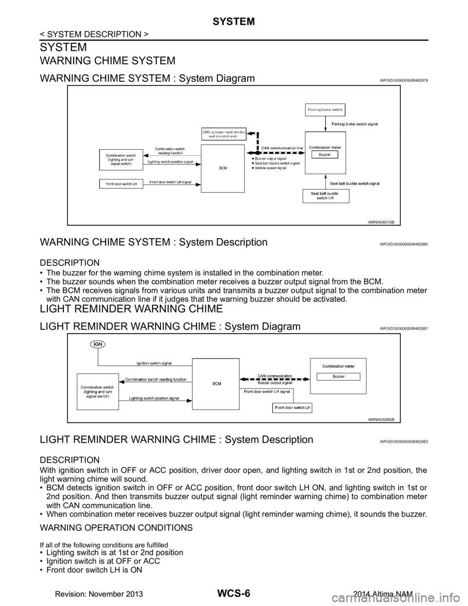
WARNING CHIME SYSTEM : System DiagramINFOID:0000000009462879
WARNING CHIME SYSTEM : System DescriptionINFOID:0000000009462880
DESCRIPTION
• The buzzer for the warning chime system is installed in the combination meter.
• The buzzer sounds when the combination meter receives a buzzer output signal from the BCM.
• The BCM receives signals from various units and transmi ts a buzzer output signal to the combination meter
with CAN communication line if it judges that the warning buzzer should be activated.
LIGHT REMINDER WARNING CHIME
LIGHT REMINDER WARNING CHIME : System DiagramINFOID:0000000009462881
LIGHT REMINDER WARNING CHIME : System DescriptionINFOID:0000000009462882
DESCRIPTION
With ignition switch in OFF or ACC position, driver door open, and lighting switch in 1st or 2nd position, the
light warning chime will sound.
• BCM detects ignition switch in OFF or ACC position, front door switch LH ON, and lighting switch in 1st or
2nd position. And then transmits buzzer output signal (li ght reminder warning chime) to combination meter
with CAN communication line.
• When combination meter receives buzzer output signal ( light reminder warning chime), it sounds the buzzer.
WARNING OPERATION CONDITIONS
If all of the following conditions are fulfilled• Lighting switch is at 1st or 2nd position
• Ignition switch is at OFF or ACC
• Front door switch LH is ON
AWNIA2651GB
AWNIA2539GB
Revision: November 20132014 Altima NAMRevision: November 20132014 Altima NAM
Page 4649 of 4801

WCS
SYSTEMWCS-7
< SYSTEM DESCRIPTION >
C
D E
F
G H
I
J
K L
M B
A
O P
WARNING CANCEL CONDITIONS
Warning is canceled if any of the following conditions is fulfilled.• Lighting switch OFF
• Ignition switch ON
• Front door switch LH is OFF
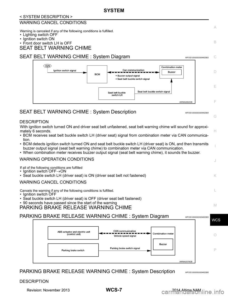
SEAT BELT WARNING CHIME
SEAT BELT WARNING CHIME : System DiagramINFOID:0000000009462883
SEAT BELT WARNING CHIME : System DescriptionINFOID:0000000009462884
DESCRIPTION
With ignition switch turned ON and driver seat belt unfastened, seat belt warning chime will sound for approxi-
mately 6 seconds.
• BCM receives seat belt buckle switch LH (driver seat) signal from combination meter via CAN communica- tion.
• BCM detects ignition switch turned ON and seat belt buckle switch LH (driver seat) is ON, and then transmits
buzzer output signal (seat belt warning chime) to combination meter via CAN communication.
• When combination meter receives buzzer output signal (seat belt warning chime), it sounds the buzzer.
WARNING OPERATION CONDITIONS
If all of the following conditions are fulfilled• Ignition switch OFF→ON
• Seat buckle switch LH (driver seat) is ON (driver seat belt not fastened)
WARNING CANCEL CONDITIONS
Cancels the warning if any of the following conditions is fulfilled.• Ignition switch OFF
• Seat buckle switch LH (driver seat) is OFF (driver seat belt fastened)
• 90 seconds have passed since the start of the warning
PARKING BRAKE RELEASE WARNING CHIME
PARKING BRAKE RELEASE WARNING CHIME : System DiagramINFOID:0000000009462885
PARKING BRAKE RELEASE WARNING CHIME : System DescriptionINFOID:0000000009462886
DESCRIPTION
AWNIA2652GB
AWNIA2578GB
Revision: November 20132014 Altima NAMRevision: November 20132014 Altima NAM
Page 4651 of 4801

WCS
DIAGNOSIS SYSTEM (METER)WCS-9
< SYSTEM DESCRIPTION >
C
D E
F
G H
I
J
K L
M B
A
O P
DIAGNOSIS SYSTEM (METER)
DescriptionINFOID:0000000009941189
COMBINATION METER SE LF-DIAGNOSIS MODE
The following meter functions can be checked during Combination Meter Self-Diagnosis Mode:
• Pointer sweep of speedometer, tachometer and gauges.
• Illumination of all LCD segments and color patterns for meter displays.
• Illumination of all lamps/LEDs that are controlled by the combination meter (regardless of switch status).
STARTING COMBINATION METER SELF-DIAGNOSIS MODE
NOTE:
• Check combination meter power supply and ground circuits if self-diagnosis mode does not start. Refer to
MWI-58, "COMBINATION METER : Diagnosis Procedure"
. Replace combination meter if power supply and
ground circuits are found to be normal and self-diagnosis mode does not start. Refer to MWI-82, "Removal
and Installation".
• Combination meter self-diagnosis mode will function with the ignition switch in ON. Combination meter self-
diagnosis mode will exit upon turning the ignition switch to OFF.
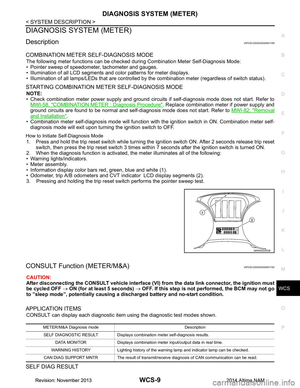
How to Initiate Se lf-Diagnosis Mode
1. Press and hold the trip reset switch while turning the ignition switch ON. After 2 seconds release trip reset
switch, then press the trip reset switch 3 times withi n 7 seconds after the ignition switch is turned ON.
2. When the diagnosis function is activated, the meter illuminates all of the following:
• Warning lights/indicators.
• Meter assembly.
• Information display color bars red, green, blue and white (1).
• Odometer, trip A/B odometers and CVT indicator LCD display segments (2).
3. Pressing and holding the trip reset switch performs the pointer sweep test.
CONSULT Function (METER/M&A)INFOID:0000000009941190
CAUTION:
After disconnecting the CONSULT vehicle interface (VI) from the data link connector, the ignition must
be cycled OFF → ON (for at least 5 seconds) → OFF. If this step is not performed, the BCM may not go
to ”sleep mode”, potentiall y causing a discharged battery and no-start condition.
APPLICATION ITEMS
CONSULT can display each diagnostic item using the diagnostic test modes shown.
SELF DIAG RESULT
AWNIA2543GB
METER/M&A Diagnosis mode Description
SELF DIAGNOSTIC RESULT Displays combination meter self-diagnosis results. DATA MONITOR Displays combination meter input/output data in real time.
WARNING HISTORY Lighting history of the warning lamp and indicator lamp can be checked.
CAN DIAG SUPPORT MNTR The result of transmit/receive diagnosis of CAN communication can be read.
Revision: November 20132014 Altima NAMRevision: November 20132014 Altima NAM