2014 NISSAN TEANA ignition
[x] Cancel search: ignitionPage 928 of 4801

DLK-160
< SYMPTOM DIAGNOSIS >
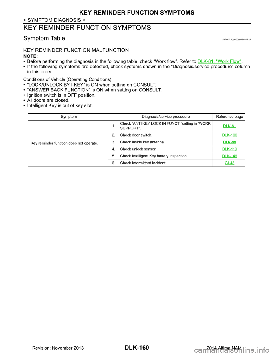
KEY REMINDER FUNCTION SYMPTOMS
KEY REMINDER FUNCTION SYMPTOMS
Symptom TableINFOID:0000000009461915
KEY REMINDER FUNCTION MALFUNCTION
NOTE:
• Before performing the diagnosis in the follo wing table, check “Work flow”. Refer to DLK-81, "Work Flow"
.
• If the following symptoms are detected, check syst ems shown in the “Diagnosis/service procedure” column
in this order.
Conditions of Vehicle (Operating Conditions)
• “LOCK/UNLOCK BY I-KEY” is ON when setting on CONSULT.
• “ANSWER BACK FUNCTION” is ON when setting on CONSULT.
• Ignition switch is in OFF position.
• All doors are closed.
• Intelligent Key is out of key slot.
Symptom Diagnosis/service procedure Reference page
Key reminder function does not operate. 1.
Check “ANTI KEY LOCK IN FUNCTI”setting in “WORK
SUPPORT”. DLK-81
2. Check door switch.
DLK-100
3. Check inside key antenna. DLK-88
4. Check unlock sensor.DLK-119
5. Check Intelligent Key battery inspection.DLK-146
6. Check Intermittent Incident. GI-43
Revision: November 20132014 Altima NAMRevision: November 20132014 Altima NAM
Page 929 of 4801

HAZARD FUNCTIONDLK-161
< SYMPTOM DIAGNOSIS >
C
D E
F
G H
I
J
L
M A
B
DLK
N
O P
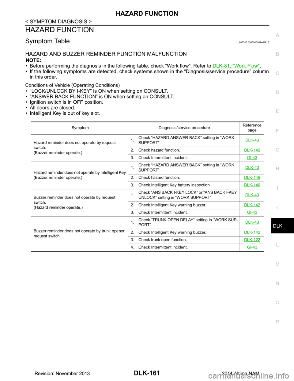
HAZARD FUNCTION
Symptom TableINFOID:0000000009461916
HAZARD AND BUZZER REMINDER FUNCTION MALFUNCTION
NOTE:
• Before performing the diagnosis in the following table, check “Work flow”. Refer to DLK-81, "Work Flow"
.
• If the following symptoms are detec ted, check systems shown in the “Diagnosis/service procedure” column
in this order.
Conditions of Vehicle (Operating Conditions)
• “LOCK/UNLOCK BY I-KEY” is ON when setting on CONSULT.
• “ANSWER BACK FUNCTION” is ON when setting on CONSULT.
• Ignition switch is in OFF position.
• All doors are closed.
• Intelligent Key is out of key slot.
Symptom Diagnosis/service procedure Reference
page
Hazard reminder does not operate by request
switch.
(Buzzer reminder operate.) 1.
Check “HAZARD ANSWER BACK” setting in “WORK
SUPPORT”. DLK-43
2. Check hazard function.
DLK-149
3. Check Intermittent incident. GI-43
Hazard reminder does not operate by Intelligent Key.
(Buzzer reminder operate.) 1.
Check “HAZARD ANSWER BACK” setting in “WORK
SUPPORT”. DLK-43
2. Check hazard function.
DLK-149
3. Check Intelligent Key battery inspection.DLK-146
Buzzer reminder does not operate by request
switch.
(Hazard reminder operate.) 1.
Check “ANS BACK I-KEY LOCK” or “ANS BACK I-KEY
UNLOCK” setting in “WORK SUPPORT”. DLK-43
2. Check Intelligent Key warning buzzer.
DLK-142
3. Check Intermittent incident. GI-43
Buzzer reminder does not operate by trunk opener
request switch. 1.
Check “TRUNK OPEN DELAY” setting in “WORK SUP-
PORT”. DLK-432. Check Intelligent Key warning buzzer.
DLK-142
3. Check trunk open function.DLK-122
4. Check Intermittent incident. GI-43
Revision: November 20132014 Altima NAMRevision: November 20132014 Altima NAM
Page 930 of 4801

DLK-162
< SYMPTOM DIAGNOSIS >
HORN FUNCTION
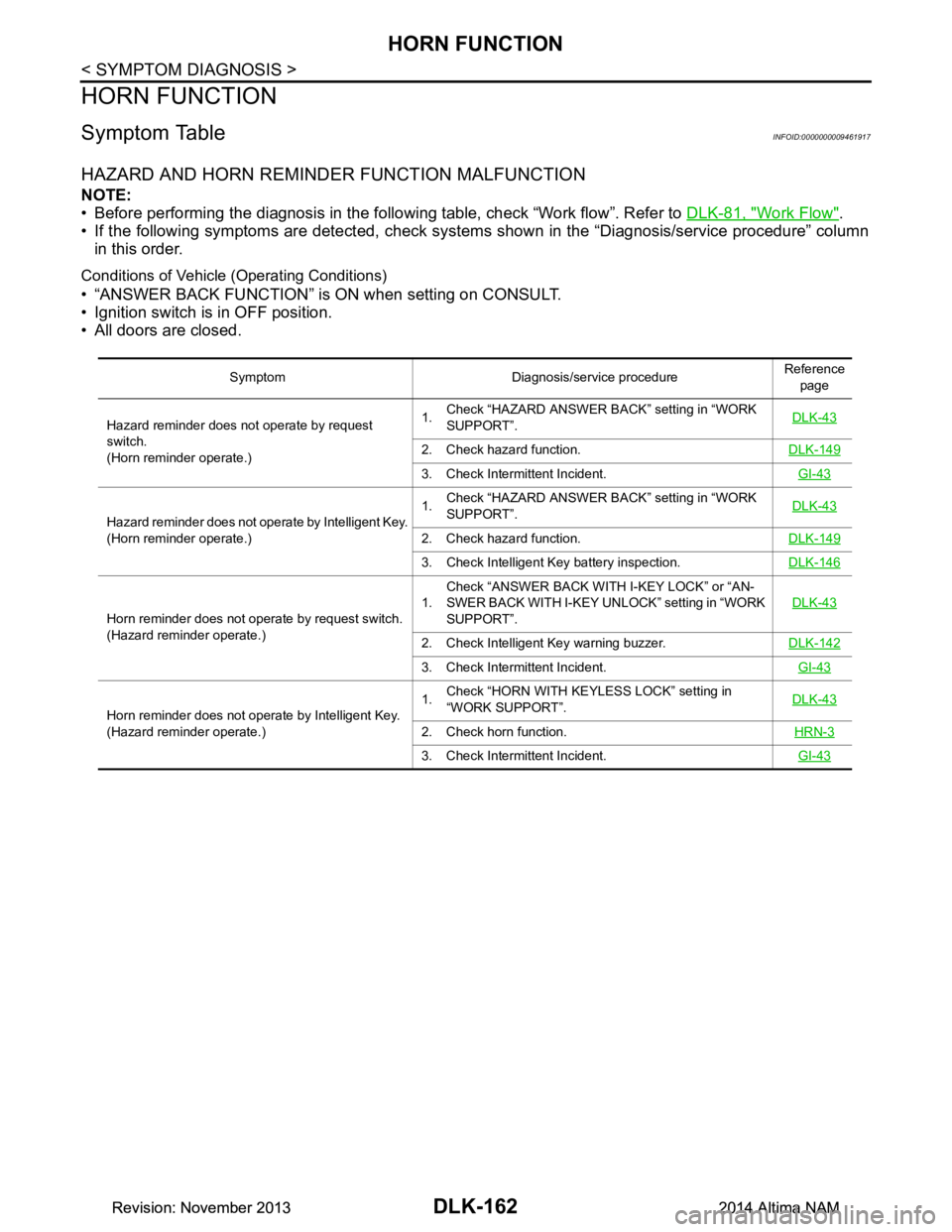
HORN FUNCTION
Symptom TableINFOID:0000000009461917
HAZARD AND HORN REMINDER FUNCTION MALFUNCTION
NOTE:
• Before performing the diagnosis in the follo wing table, check “Work flow”. Refer to DLK-81, "Work Flow"
.
• If the following symptoms are detected, check syst ems shown in the “Diagnosis/service procedure” column
in this order.
Conditions of Vehicle (Operating Conditions)
• “ANSWER BACK FUNCTION” is ON when setting on CONSULT.
• Ignition switch is in OFF position.
• All doors are closed.
Symptom Diagnosis/service procedure Reference
page
Hazard reminder does not operate by request
switch.
(Horn reminder operate.) 1.
Check “HAZARD ANSWER BACK” setting in “WORK
SUPPORT”. DLK-43
2. Check hazard function.
DLK-149
3. Check Intermittent Incident. GI-43
Hazard reminder does not operate by Intelligent Key.
(Horn reminder operate.) 1.
Check “HAZARD ANSWER BACK” setting in “WORK
SUPPORT”. DLK-43
2. Check hazard function.
DLK-149
3. Check Intelligent Key battery inspection.DLK-146
Horn reminder does not operate by request switch.
(Hazard reminder operate.) 1.
Check “ANSWER BACK WITH I-KEY LOCK” or “AN-
SWER BACK WITH I-KEY UNLOCK” setting in “WORK
SUPPORT”. DLK-43
2. Check Intelligent Key warning buzzer.
DLK-142
3. Check Intermittent Incident. GI-43
Horn reminder does not operate by Intelligent Key.
(Hazard reminder operate.) 1.
Check “HORN WITH KEYLESS LOCK” setting in
“WORK SUPPORT”. DLK-43
2. Check horn function.
HRN-3
3. Check Intermittent Incident. GI-43
Revision: November 20132014 Altima NAMRevision: November 20132014 Altima NAM
Page 952 of 4801

DLK-184
< REMOVAL AND INSTALLATION >
FRONT DOOR
FRONT DOOR
DOOR ASSEMBLY
DOOR ASSEMBLY : Removal and InstallationINFOID:0000000009461933
CAUTION:
• Use two people when removing or installing the front door assembly due to its heavy weight.
• When removing and installing front door assembl y, support front door with a suitable tool.
• Do not use air tools or el ectric tools for servicing.
• Before servicing, turn ignition sw itch OFF, disconnect both battery terminals and wait at least three
minutes.
NOTE:
LH side shown; RH side similar.
REMOVAL
1. Disconnect the battery negative and positive terminals and wait at least three minutes with the side air bag (satellite) sensor (if equipped).
2. Remove front door harness grommet LH (1) then pull out door harness from body (2).
3. Disconnect the harness connectors (A) from the front door har- ness.
4. Remove the check link bolt (body side).
JMKIA8070ZZ
JMKIA8071ZZ
Revision: November 20132014 Altima NAMRevision: November 20132014 Altima NAM
Page 1001 of 4801

EC-1
ENGINE
C
D E
F
G H
I
J
K L
M
SECTION EC
A
EC
N
O P
CONTENTS
ENGINE CONTROL SYSTEM
QR25DE
PRECAUTION ................ ..............................
15
PRECAUTIONS .............................................. ....15
Precaution for Supplemental Restraint System
(SRS) "AIR BAG" and "SEAT BELT PRE-TEN-
SIONER" ............................................................. ....
15
Precaution for Procedure without Cowl Top Cover ....15
On Board Diagnostic (OBD) System of Engine
and CVT .............................................................. ....
15
General Precautions ...............................................16
PREPARATION ...........................................19
PREPARATION .............................................. ....19
Special Service Tools .......................................... ....19
Commercial Service Tools ......................................19
SYSTEM DESCRIPTION .............................21
COMPONENT PARTS ................................... ....21
Component Parts Location ................................ ....21
ECM ........................................................................25
Accelerator Pedal Position Sensor ...................... ....25
Electric Throttle Control Actuator ........................ ....25
Ignition Coil With Power Transistor .........................26
Fuel Injector ........................................................ ....26
Fuel Level Sensor Unit and Fuel Pump .............. ....26
Fuel Tank Temperature Sensor .......................... ....27
Mass Air Flow Sensor (With Intake Air Tempera-
ture Sensor) ........................................................ ....
27
Manifold Absolute Pressure Sensor ........................28
Engine Coolant Temperature Sensor .................. ....28
Crankshaft Position Sensor (POS) ..........................29
Camshaft Position Sens or (PHASE) .......................29
Intake Valve Timing Cont rol Solenoid Valve ...........30
Intake Valve Timing Intermediate Lock Control
Solenoid Valve .................................................... ....
30
Exhaust Valve Timing Control Position Sensor .......30
Exhaust Valve Timing Control Solenoid Valve ........31
Intake Manifold Runner Control Valve ................. ....31
Intake Manifold Tuning Valve ..................................31
Air Fuel Ratio (A/F) Sensor 1 ..................................32
Heated Oxygen Sensor 2 ........................................32
Knock Sensor ..........................................................33
Engine Oil Pressure Sensor ....................................33
Engine Oil Temperature Sensor .......................... ....33
Cooling Fan .............................................................34
EVAP Canister .........................................................34
EVAP Canister Purge Volu me Control Solenoid
Valve .................................................................... ....
34
EVAP Canister Vent Control Valve ..........................35
EVAP Control System Pres sure Sensor ..................35
Battery Current Sensor (With Battery Tempera-
ture Sensor) ......................................................... ....
35
Malfunction Indicator lamp (MIL) .............................36
Oil Pressure Warning Lamp ....................................36
Refrigerant Pressure Sensor ............................... ....36
Stop Lamp Switch & Brake Pedal Position Switch ....36
ASCD Steering Switch .............................................37
Information Display ..................................................37
STRUCTURE AND OPERATION .....................38
Positive Crankcase Ventilation ................................38
On Board Refueling Vapor Recovery (ORVR) ........39
SYSTEM ............................................................40
ENGINE CONTROL SYSTEM ........................ ...........40
ENGINE CONTROL SYSTEM : System Descrip-
tion ....................................................................... ....
40
ENGINE CONTROL SYSTEM : Fail Safe ..............41
MULTIPORT FUEL INJECTION SYSTEM ................43
MULTIPORT FUEL INJECTION SYSTEM : Sys-
tem Description (with auto matic air conditioner) ......
43
MULTIPORT FUEL INJECTION SYSTEM : Sys-
tem Description (with manual air conditioner) .........
46
ELECTRIC IGNITION SYSTEM .................................48
ELECTRIC IGNITION SYSTEM : System De-
scription ............................................................... ....
48
Revision: November 20132014 Altima NAMRevision: November 20132014 Altima NAM
Page 1007 of 4801

EC-7
C
D E
F
G H
I
J
K L
M
EC A
N
O P
P2101 ELECTRIC THROTTLE CONTROL
FUNCTION ..................................................... ..
475
DTC Logic ........................................................... ..475
Diagnosis Procedure .............................................475
Component Inspection ..........................................477
P2118 THROTTLE CONTROL MOTOR ..........478
DTC Logic ........................................................... ..478
Diagnosis Procedure .............................................478
Component Inspection ..........................................479
P2119 ELECTRIC THROTTLE CONTROL
ACTUATOR .................................................... ..
480
DTC Logic ........................................................... ..480
Diagnosis Procedure .............................................480
P2122, P2123 APP SENSOR ...........................482
DTC Logic ........................................................... ..482
Diagnosis Procedure .............................................482
Component Inspection ..........................................484
P2127, P2128 APP SENSOR ...........................485
DTC Logic ........................................................... ..485
Diagnosis Procedure .............................................485
Component Inspection ..........................................486
P2135 TP SENSOR ..........................................488
DTC Logic ........................................................... ..488
Diagnosis Procedure .............................................488
Component Inspection ..........................................490
P2138 APP SENSOR .......................................491
DTC Logic ........................................................... ..491
Diagnosis Procedure .............................................491
Component Inspection ..........................................493
P2610 ECM INTERNAL TIMER .......................494
Description .......................................................... ..494
DTC Logic .............................................................494
Diagnosis Procedure .............................................495
BRAKE PEDAL POSITION SWITCH ...............496
Component Function Check ................................ ..496
Diagnosis Procedure .............................................496
Component Inspection (Brake Pedal Position
Switch) ................................................................ ..
497
COOLING FAN .................................................499
Component Function Check ................................ ..499
Diagnosis Procedure .............................................499
Component Inspection (Cooling Fan Motor) .........501
Component Inspection (C ooling Fan Relay) .........502
ELECTRICAL LOAD SIGNAL ....................... ..503
Description .......................................................... ..503
Component Function Check ..................................503
Diagnosis Procedure .............................................503
FUEL INJECTOR .............................................505
Component Function Check ................................ ..505
Diagnosis Procedure .............................................505
Component Inspection ......................................... ..506
FUEL PUMP ....................................................508
Description .............................................................508
Component Function Check ..................................508
Diagnosis Procedure .............................................508
Component Inspection ...........................................510
IGNITION SIGNAL ..........................................511
Component Function Check ..................................511
Diagnosis Procedure .............................................511
Component Inspection (Ignition Coil with Power
Transistor) ........................................................... ..
514
Component Inspection (Condenser) ......................515
INFORMATION DISPLAY (ASCD) .................516
Component Function Check ..................................516
Diagnosis Procedure .............................................516
MALFUNCTION INDICATOR LAMP ..............517
Component Function Check ..................................517
Diagnosis Procedure .............................................517
ON BOARD REFUELING VAPOR RECOV-
ERY (ORVR) ....................................................
518
Component Function Check ................................ ..518
Diagnosis Procedure .............................................518
Component Inspection ...........................................520
REFRIGERANT PRESSURE SENSOR ..........523
Component Function Check ..................................523
Diagnosis Procedure .............................................523
SENSOR POWER SUPPLY 2 CIRCUIT .........525
Description .............................................................525
Diagnosis Procedure .............................................525
SYMPTOM DIAGNOSIS ............................527
ENGINE CONTRO L SYSTEM ........................527
Symptom Table ................................................... ..527
INFORMATION DISPLAY IS MALFUNCTION-
ING ..................................................................
532
Diagnosis Procedure ........................................... ..532
NORMAL OPERATING CONDITION .............533
Description .............................................................533
PERIODIC MAINTENANCE ......................534
IDLE SPEED .... ...............................................534
Inspection ............................................................ ..534
IGNITION TIMING ...........................................535
Inspection ..............................................................535
EVAPORATIVE EMISSION SYSTEM .............536
Inspection ..............................................................536
EVAP LEAK CHECK ......................................537
Inspection ..............................................................537
Revision: November 20132014 Altima NAMRevision: November 20132014 Altima NAM
Page 1008 of 4801

EC-8
POSITIVE CRANKCASE VENTILATION ........539
Inspection ............................................................ ..539
REMOVAL AND INSTALLATION ..............540
ECM ................................................................ .540
Removal and Installation ..................................... ..540
SERVICE DATA AND SPECIFICATIONS
(SDS) .............. ............................................
541
SERVICE DATA AND SPECIFICATIONS
(SDS) ............................................................... .
541
Idle Speed ........................................................... ..541
Ignition Timing .......................................................541
Calculated Load Value ..........................................541
Mass Air Flow Sensor ............................................541
VQ35DE
PRECAUTION .............. ..............................
542
PRECAUTIONS .............................................. .542
Precaution for Supplemental Restraint System
(SRS) "AIR BAG" and "SEAT BELT PRE-TEN-
SIONER" .............................................................. ..
542
On Board Diagnostic (OBD) System of Engine
and CVT .............................................................. ..
542
General Precautions ..............................................543
PREPARATION ..........................................546
PREPARATION .............................................. .546
Special Service Tools .......................................... ..546
Commercial Service Tools .....................................546
SYSTEM DESCRIPTION ...........................548
COMPONENT PARTS .................................... .548
ENGINE CONTROL SYSTEM .................................548
ENGINE CONTROL SYSTEM : Component Parts
Location ............................................................... ..
548
Accelerator Pedal Position Sensor ........................552
Air Fuel Ratio (A/F) Sensor 1 ................................552
ASCD Steering Switch ...........................................553
Battery Current Sensor (With Battery Tempera-
ture Sensor) ......................................................... ..
553
Camshaft Position Sensor (PHASE) .....................554
Cooling Fan ......................................................... ..554
Crankshaft Position Sensor (POS) ........................554
ECM .......................................................................555
Electric Throttle Control Actuator ......................... ..555
Electronic Controlled Engine Mount .................... ..556
Engine Coolant Temperature Sensor ....................556
Engine Oil Pressure Sensor ................................ ..557
Engine Oil Temperature Sensor ............................557
EVAP Canister ..................................... ..................557
EVAP Canister Purge Volu me Control Solenoid
Valve .................................................................... ..
557
EVAP Canister Vent Control Valve ........................558
EVAP Control System Pressu re Sensor ................558
Fuel Injector ......................................................... .558
Fuel Level Sensor Unit and Fuel Pump (With Fuel
Tank Temperature Sensor) .................................. .
558
Heated Oxygen Sensor 2 ......................................559
Ignition Coil (With Power Transistor) ....................560
Intake Valve Timing Control Solenoid Valve .........560
Knock Sensor ....................................................... .560
Malfunction Indicator lamp (MIL) ...........................560
Mass Air Flow Sensor (With Intake Air Tempera-
ture Sensor) ......................................................... .
560
Oil Pressure Warning Lamp ..................................561
Power Valve Actuator 1 and 2 ..............................561
Refrigerant Pressure Sensor ................................562
Stop Lamp Switch & Brak e Pedal Position Switch .562
VIAS Control Solenoid Valve 1 and 2 .................. .562
STRUCTURE AND OPERATION .....................563
Positive Crankcase Ventilation (PCV) ...................563
On Board Refueling Vapor Recovery (ORVR) ..... .564
SYSTEM ...........................................................565
ENGINE CONTROL SYSTEM ................................ .565
ENGINE CONTROL SYSTEM : System Descrip-
tion ....................................................................... .
565
ENGINE CONTROL SYSTEM : Fail-safe .............566
MULTIPORT FUEL INJECTION SYSTEM ............. .568
MULTIPORT FUEL INJECTION SYSTEM : Sys-
tem Description .................................................... .
568
ELECTRIC IGNITION SYSTEM ............................. .571
ELECTRIC IGNITION SYSTEM : System De-
scription ................................................................ .
571
AIR CONDITIONING CUT CONTROL ................... .572
AIR CONDITIONING CUT CONTROL : System
Description ........................................................... .
573
AUTOMATIC SPEED CONTROL DEVICE (ASCD) .574
AUTOMATIC SPEED CONTROL DEVICE (AS-
CD) : System Description ..................................... .
574
COOLING FAN CONTROL .................................... .575
COOLING FAN CONTROL : System Description .575
ELECTRONIC CONTROLLED ENGINE MOUNT .. .577
ELECTRONIC CONTROLLED ENGINE MOUNT
: System Description ............................................ .
577
EVAPORATIVE EMISSION SYSTEM .....................579
EVAPORATIVE EMISSION SYSTEM : System
Description ........................................................... .
580
THROTTLE CONTROL ...........................................581
THROTTLE CONTROL : Syst em Description ......581
INTAKE VALVE TIMING CONTROL ..................... .582
INTAKE VALVE TIMING CONTROL : System De-
scription ................................................................ .
583
ENGINE PROTECTION CONTROL AT LOW EN-
GINE OIL PRESSURE ........................................... .
583
Revision: November 20132014 Altima NAMRevision: November 20132014 Altima NAM
Page 1013 of 4801

EC-13
C
D E
F
G H
I
J
K L
M
EC A
N
O P
P1574 ASCD VEHICLE SPEED SENSOR .... ..918
Description .......................................................... ..918
DTC Logic .............................................................918
Diagnosis Procedure .............................................918
P1800 VIAS CONTROL SOLENOID VALVE 1 ..920
DTC Logic ........................................................... ..920
Diagnosis Procedure .............................................920
Component Inspection ..........................................921
P1801 VIAS CONTROL SOLENOID VALVE 2 ..922
DTC Logic ........................................................... ..922
Diagnosis Procedure .............................................922
Component Inspection ..........................................923
P1805 BRAKE SWITCH ................................. ..924
Description .......................................................... ..924
DTC Logic .............................................................924
Diagnosis Procedure .............................................924
Component Inspection (Stop Lamp Switch) ..........926
Component Inspection (Stop Lamp Relay) ...........926
P2096, P2097, P2098, P2099 A/F SENSOR 1 ..927
DTC Logic ........................................................... ..927
Diagnosis Procedure .............................................927
P2100, P2103 THROTTLE CONTROL MO-
TOR RELAY ................................................... ..
931
DTC Logic ........................................................... ..931
Diagnosis Procedure .............................................931
P2101 ELECTRIC THROTTLE CONTROL
FUNCTION ..................................................... ..
933
DTC Logic ........................................................... ..933
Diagnosis Procedure .............................................933
Component Inspection ..........................................935
P2118 THROTTLE CONTROL MOTOR ..........936
DTC Logic ........................................................... ..936
Diagnosis Procedure .............................................936
Component Inspection ..........................................937
P2119 ELECTRIC THROTTLE CONTROL
ACTUATOR .................................................... ..
938
DTC Logic ........................................................... ..938
Diagnosis Procedure .............................................938
P2122, P2123 APP SENSOR ...........................940
DTC Logic ........................................................... ..940
Diagnosis Procedure .............................................940
Component Inspection ..........................................941
P2127, P2128 APP SENSOR ...........................942
DTC Logic ........................................................... ..942
Diagnosis Procedure .............................................942
Component Inspection ..........................................943
P2135 TP SENSOR ..........................................945
DTC Logic ........................................................... ..945
Diagnosis Procedure .............................................945
Component Inspection ..........................................946
P2138 APP SENSOR ......................................947
DTC Logic ............................................................ ..947
Diagnosis Procedure .............................................947
Component Inspection ...........................................949
BRAKE PEDAL POSITION SWITCH .............950
Component Function Check ..................................950
Diagnosis Procedure .............................................950
Component Inspection (Brake Pedal Position
Switch) ................................................................. ..
951
ASCD INDICATOR ..........................................952
Component Function Check ..................................952
Diagnosis Procedure .............................................952
COOLING FAN ................................................953
Component Function Check ..................................953
Diagnosis Procedure .............................................953
Component Inspection (Cooling Fan Motor) ..........955
Component Inspection (Cooling Fan Relay) ..........956
ELECTRICAL LOAD SIGNAL ........................957
Description .............................................................957
Component Function Check ..................................957
Diagnosis Procedure .............................................957
ELECTRONIC CONTROLLED ENGINE
MOUNT ............................................................
959
Component Function Check ................................ ..959
Diagnosis Procedure .............................................959
Component Inspection ...........................................960
FUEL INJECTOR ............................................962
Component Function Check ..................................962
Diagnosis Procedure .............................................962
Component Inspection ...........................................963
FUEL PUMP ....................................................965
Component Function Check ..................................965
Diagnosis Procedure .............................................965
Component Inspection ...........................................966
IGNITION SIGNAL ..........................................967
Component Function Check ..................................967
Diagnosis Procedure .............................................967
Component Inspection (Ignition Coil with Power
Transistor) ........................................................... ..
970
Component Inspection (Condenser) ......................971
INFORMATION DISPLAY (ASCD) .................972
Component Function Check ..................................972
Diagnosis Procedure .............................................972
MALFUNCTION INDICATOR LAMP ..............973
Component Function Check ..................................973
Diagnosis Procedure .............................................973
ON BOARD REFUELING VAPOR RECOV-
ERY (ORVR) ....................................................
974
Component Function Check ................................ ..974
Diagnosis Procedure .............................................974
Revision: November 20132014 Altima NAMRevision: November 20132014 Altima NAM