2014 NISSAN TEANA wheel
[x] Cancel search: wheelPage 2941 of 4801
INSTRUMENT PANEL ASSEMBLYIP-15
< REMOVAL AND INSTALLATION >
C
D E
F
G H
I
K L
M A
B
IP
N
O P
Removal and Installation INFOID:0000000009461379
CAUTION:
• Be careful not to scratch instrument panel pad and other parts.
• Whenever a suitable tool is used, always wrap a cloth around the end of the tool to protect compo-
nents from damage.
• Before servicing, turn ignition swit ch OFF, disconnect both battery terminals and wait at least three
minutes.
REMOVAL
1. Disconnect the negative and positive bat tery terminals, then wait at least three minutes. Refer to PG-73,
"Removal and Installation (Battery)"
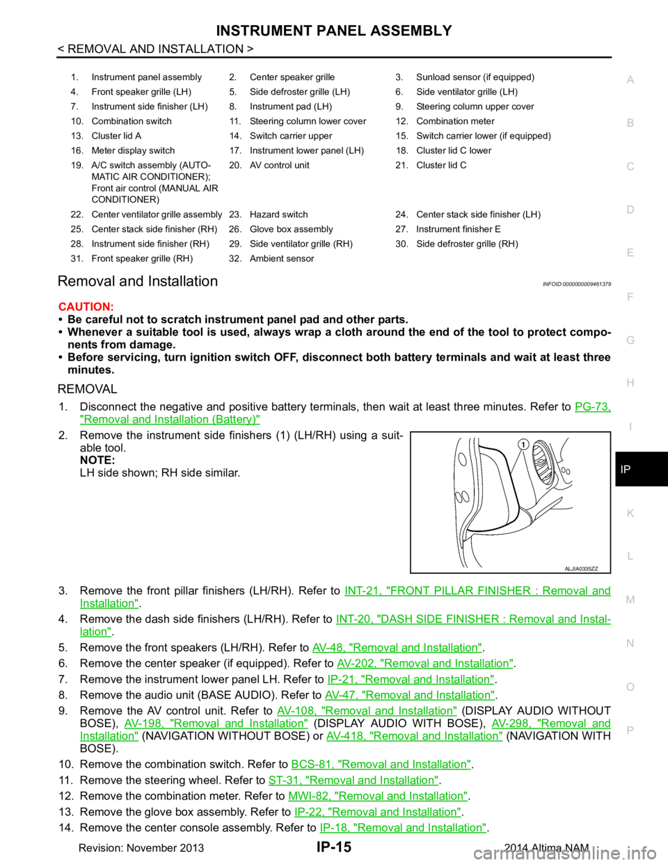
2. Remove the instrument side finishers (1) (LH/RH) using a suit-
able tool.
NOTE:
LH side shown; RH side similar.
3. Remove the front pillar finishers (LH/RH). Refer to INT-21, "FRONT PILLAR FINISHER : Removal and
Installation".
4. Remove the dash side finishers (LH/RH). Refer to INT-20, "DASH SIDE FINISHER : Removal and Instal-
lation".
5. Remove the front speakers (LH/RH). Refer to AV-48, "Removal and Installation"
.
6. Remove the center speaker (if equipped). Refer to AV-202, "Removal and Installation"
.
7. Remove the instrument lower panel LH. Refer to IP-21, "Removal and Installation"
.
8. Remove the audio unit (BASE AUDIO). Refer to AV-47, "Removal and Installation"
.
9. Remove the AV control unit. Refer to AV-108, "Removal and Installation"
(DISPLAY AUDIO WITHOUT
BOSE), AV-198, "Removal and Installation"
(DISPLAY AUDIO WITH BOSE), AV-298, "Removal and
Installation" (NAVIGATION WITHOUT BOSE) or AV-418, "Removal and Installation" ( N AV I G AT I O N W I T H
BOSE).
10. Remove the combination switch. Refer to BCS-81, "Removal and Installation"
.
11. Remove the steering wheel. Refer to ST-31, "Removal and Installation"
.
12. Remove the combination meter. Refer to MWI-82, "Removal and Installation"
.
13. Remove the glove box assembly. Refer to IP-22, "Removal and Installation"
.
14. Remove the center console assembly. Refer to IP-18, "Removal and Installation"
.
1. Instrument panel assembly 2. Center speaker grille 3. Sunload sensor (if equipped)
4. Front speaker grille (LH) 5. Side defroster grille (LH) 6. Side ventilator grille (LH)
7. Instrument side finisher (LH) 8. Instrument pad (LH) 9. Steering column upper cover
10. Combination switch 11. Steering column lower cover 12. Combination meter
13. Cluster lid A 14. Switch carrier upper 15. Switch carrier lower (if equipped)
16. Meter display switch 17. Instrument lower panel (LH) 18. Cluster lid C lower
19. A/C switch assembly (AUTO- MATIC AIR CONDITIONER);
Front air control (MANUAL AIR
CONDITIONER) 20. AV control unit 21. Cluster lid C
22. Center ventilator grille assembly 23. Hazard switch 24. Center stack side finisher (LH)
25. Center stack side finisher (RH) 26. Glove box assembly 27. Instrument finisher E
28. Instrument side finisher (RH) 29. Side ventilator grille (RH) 30. Side defroster grille (RH)
31. Front speaker grille (RH) 32. Ambient sensor
ALJIA0335ZZ
Revision: November 20132014 Altima NAM
Page 2943 of 4801
STEERING COLUMN COVERSIP-17
< REMOVAL AND INSTALLATION >
C
D E
F
G H
I
K L
M A
B
IP
N
O P
STEERING COLUMN COVERS
Removal and InstallationINFOID:0000000009461380
REMOVAL
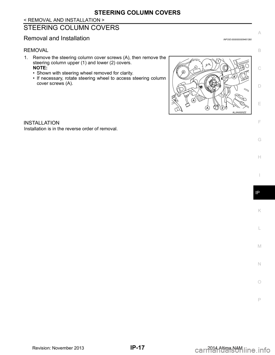
1. Remove the steering column cover screws (A), then remove the steering column upper (1) and lower (2) covers.
NOTE:
• Shown with steering wheel removed for clarity.
• If necessary, rotate steering wheel to access steering column
cover screws (A).
INSTALLATION
Installation is in the reverse order of removal.
ALJIA0025ZZ
Revision: November 20132014 Altima NAM
Page 3166 of 4801
![NISSAN TEANA 2014 Service Manual
LU-16
< REMOVAL AND INSTALLATION >[QR25DE]
OIL COOLER
OIL COOLER
Exploded ViewINFOID:0000000009461035
Removal and InstallationINFOID:0000000009461036
WARNING:
Be careful not to burn yourself, as eng NISSAN TEANA 2014 Service Manual
LU-16
< REMOVAL AND INSTALLATION >[QR25DE]
OIL COOLER
OIL COOLER
Exploded ViewINFOID:0000000009461035
Removal and InstallationINFOID:0000000009461036
WARNING:
Be careful not to burn yourself, as eng](/manual-img/5/57390/w960_57390-3165.png)
LU-16
< REMOVAL AND INSTALLATION >[QR25DE]
OIL COOLER
OIL COOLER
Exploded ViewINFOID:0000000009461035
Removal and InstallationINFOID:0000000009461036
WARNING:
Be careful not to burn yourself, as engi ne oil and engine coolant may be hot.
NOTE:
When removing components such as hoses, tubes/lines, etc. , cap or plug openings to prevent fluid from spill-
ing.
REMOVAL
1. Remove RH front road wheel and tire. Refer to WT-55, "Adjustment".
2. Remove RH fender protector. Refer to EXT-26, "FENDER PROTECTOR : Removal and Installation"
.
3. Drain engine coolant by removing water drain plug on cylinder block and radiator drain plug. Refer to CO-
12, "Changing Engine Coolant".
4. Disconnect hoses from the oil cooler.
5. Remove oil cooler bolts in reverse numerical order.
6. Remove oil cooler.
7. Remove relief valve and O-rings.
INSTALLATION
Installation is in the reverse order of removal.
CAUTION:
1-5. Tightening sequence 6. O-ring 7. Relief Valve
8. Oil cooler A. To water hose
AWBIA1295GB
Revision: November 20132014 Altima NAM
Page 3183 of 4801
![NISSAN TEANA 2014 Service Manual
OIL COOLERLU-33
< REMOVAL AND INSTALLATION > [VQ35DE]
C
D E
F
G H
I
J
K L
M A
LU
NP
O
When removing components such as hoses, tubes/lines, etc.
, cap or plug openings to prevent fluid from spill-
in NISSAN TEANA 2014 Service Manual
OIL COOLERLU-33
< REMOVAL AND INSTALLATION > [VQ35DE]
C
D E
F
G H
I
J
K L
M A
LU
NP
O
When removing components such as hoses, tubes/lines, etc.
, cap or plug openings to prevent fluid from spill-
in](/manual-img/5/57390/w960_57390-3182.png)
OIL COOLERLU-33
< REMOVAL AND INSTALLATION > [VQ35DE]
C
D E
F
G H
I
J
K L
M A
LU
NP
O
When removing components such as hoses, tubes/lines, etc.
, cap or plug openings to prevent fluid from spill-
ing.
REMOVAL
1. Remove the engine under cover. Refer to EXT-17, "Removal and Installation".
2. Remove the RH wheel and tire. Refer to WT-53, "Inspection"
.
3. Remove the front fender protector side cover RH. Refer to EXT-26, "FENDER PROTECTOR : Exploded
View".
4. Drain engine coolant. Refer to CO-36, "Changing Engine Coolant"
.
CAUTION:
Do not spill coolant on the drive belt.
5. Disconnect water hoses from oil cooler.
6. Remove the oil filter. Refer to LU-27, "Removal and Installation"
.
7. Remove oil cooler.
8. Remove core support cover. Refer to DLK-179, "Removal and Installation"
.
9. Remove front air duct. Refer to EM-84, "Removal and Installation"
.
10. Remove reservoir tank. Refer to CO-40, "Exploded View"
.
INSPECTION AFTER REMOVAL
1. Check oil cooler for cracks.
2. Check oil cooler for clogging by blowing through coolant inlet. If necessary, replace oil cooler.
Oil Pressure Relief Valve
Inspect oil pressure relief valve for movement, cracks and breaks by pushing the ball. If replacement is neces-
sary, remove valve by prying it out with a suitable tool. Install a new valve in place by tapping it.
INSTALLATION
Installation is in the reverse order of removal.
CAUTION:
• Do not reuse O-ring.
• Do not reuse copper gasket.
• When installing the oil cooler, align the oil cooler slot with the stopper of the oil pan.
INSPECTION AFTER INSTALLATION
1. Check the engine oil level and the engine coolant level and add engine oil and engine coolant. Refer to LU-9, "Inspection"
and CO-11, "System Inspection".
2. Start the engine, and check that there is no leakage of engine oil or engine coolant.
3. Stop the engine and wait for 10 minutes.
4. Check the engine oil level and the engine coolant level again. Refer to LU-9, "Inspection"
and CO-11,
"System Inspection".
Revision: November 20132014 Altima NAM
Page 3186 of 4801

MA-2
OIL FILTER : Removal and Installation ..................27
SPARK PLUG ........................................................ ...28
SPARK PLUG : Removal and Installation ..............29
EVAP VAPOR LINES ............................................. ...30
EVAP VAPOR LINES : Inspection ..........................30
CHASSIS AND BODY MAINTENANCE ......... ...31
IN-CABIN MICROFILTER ...................................... ...31
IN-CABIN MICROFILTER : Removal and Installa-
tion ....................................................................... ...
31
EXHAUST SYSTEM ............................................... ...31
EXHAUST SYSTEM : Checking Exhaust System ...31
CVT FLUID ............................................................. ...31
CVT FLUID : RE0F10D ..........................................32
CVT FLUID : Inspection ..........................................32
CVT FLUID : Replacement .....................................32
CVT FLUID : Adjustment ........................................34
CVT FLUID : RE0F10E ..........................................35
CVT FLUID : Inspection ..........................................35
CVT FLUID : Replacement .....................................35
CVT FLUID : Adjustment ........................................37
WHEELS ................................................................ ...38
WHEELS : Inspection .............................................38
WHEELS : Adjustment ...........................................39
BRAKE FLUID LEVEL AND LEAKS ........................40
BRAKE FLUID LEVEL AND LEAKS : Inspection ...40
BRAKE LINES AND CABLES ............................... ...41
BRAKE LINES AND CABLES : Inspection .............41
BRAKE FLUID ........................................................ ...41
BRAKE FLUID : Drain and Refill .............................41
DISC BRAKE .......................................................... ...42
DISC BRAKE : Front Brake Pad .............................42
DISC BRAKE : Inspection .......................................42
DISC BRAKE : Front Brake Rotor ...........................42
DISC BRAKE : Inspection .......................................42
DISC BRAKE : Rear Brake Pad ..............................43
DISC BRAKE : Inspection .......................................43
DISC BRAKE : Rear Brake Rotor ...........................43
DISC BRAKE : Inspection .......................................43
STEERING GEAR AND LINKAGE ........................ ...43
STEERING GEAR AND LINKAGE : Inspection ......43
POWER STEERING FLUID AND LINES ............... ...43
POWER STEERING FLUID AND LINES : Inspec-
tion ....................................................................... ...
44
AXLE AND SUSPENSION PARTS ........................ ...44
AXLE AND SUSPENSION PARTS : Inspection .....44
DRIVE SHAFT ........................................................ ...45
DRIVE SHAFT : Inspection .....................................45
LOCKS, HINGES AND HOOD LATCH .................. ...45
LOCKS, HINGES AND HOOD LATCH : Lubricat-
ing ........................................................................ ...
45
SEAT BELT, BUCKLES, RETRACTORS, AN-
CHORS AND ADJUSTERS ................................... ...
45
SEAT BELT, BUCKLES, RETRACTORS, AN-
CHORS AND ADJUSTERS : Inspection .............. ...
45
Revision: November 20132014 Altima NAM
Page 3189 of 4801
GENERAL MAINTENANCEMA-5
< PERIODIC MAINTENANCE >
C
D E
F
G H
I
J
K L
M B
MA
N
O A
PERIODIC MAINTENANCE
GENERAL MAINTENANCE
FOR USA AND CANADA
FOR USA AND CANADA : Explana
tion of General MaintenanceINFOID:0000000009464530
General maintenance includes those items which shoul d be checked during the normal day-to-day operation
of the vehicle. They are essential if the vehicle is to continue operating properly. The owners can perform
checks and inspections themselves or have their NISSAN dealers do them.
OUTSIDE THE VEHICLE
The maintenance items listed here should be performed from time to time, unless otherwise specified.
INSIDE THE VEHICLE
The maintenance items listed here should be checked on a regular basis, such as when performing periodic maintenance, cleaning the vehicle,
etc.
Item Reference page
Tires Check the pressure with a gauge often and always prior to long distance trips.
Adjust the pressure in all tires, including the spare, to the pressure specified.
Check carefully for damage, cuts or excessive wear. MA-39
Wheel nuts
When checking the tires, make sure no nuts are missing, and check for any loose
nuts. Tighten if necessary. MA-39
Tire rotation
Tires should be rotated every 5,000 miles (8,000 km). MA-39
Tire Pressure Monitor-
ing System (TPMS)
transmitter compo-
nents Replace the TPMS transmitter grommet seal, valve core and cap when the tires
are replaced due to wear or age. WT-57
Wheel alignment and
balance If the vehicle should pull to either side while driving on a straight and level road,
or if you detect uneven or abnormal tire wear, there may be a need for wheel
alignment. If the steering wheel or seat vibrates at normal highway speeds,
wheel balancing may be needed. For additional information regarding tires, refer
to "Important Tire Safety Information" (US) or "Tire Safety Information" (Canada)
in the NISSAN Warranty Information Booklet. FSU-25
Windshield
Clean the windshield on a regular basis. Check the windshield at least every six
months for cracks or other damage. Repair as necessary. —
Windshield wiper
blades Check for cracks or wear if they do not wipe properly. —
Doors and engine
hood Check that all doors and the engine hood operate properly. Also make sure that
all latches lock securely. Lubricate if necessary. Make sure that the secondary
latch keeps the hood from opening when the primary latch is released.
When driving in areas using road salt or other corrosive materials, check for lu-
brication frequently. MA-45, "LOCKS, HING-
ES AND HOOD LATCH :
Lubricating"
Lamps
Make sure that the headlamps, stop lamps, tail lamps, turn signal lamps, and oth-
er lamps are all operating properly and installed securely. Also check headlamp
aim. Clean the headlamps on a regular basis. EXL-122
Item
Reference page
Warning lamps and
chimes Make sure that all warning lamps and chimes are operating properly. —
Windshield wiper and
washer Check that the wipers and washer operate properly and that the wipers do not
streak. —
Windshield defroster Check that the air comes out of the defroster outlets properly and in sufficient
quantity when operating the heater or air conditioner. —
Steering wheel Check that it has the specified play. Check for changes in the steering condition,
such as excessive play, hard steering or strange noises.
Free play: Less than 35 mm (1.38 in) —
Revision: November 20132014 Altima NAM
Page 3222 of 4801
MA-38
< PERIODIC MAINTENANCE >
CHASSIS AND BODY MAINTENANCE
CAUTION:
Do not reuse O-ring.
14. Lift down the vehicle.
15. Stop the engine.
WHEELS
WHEELS : InspectionINFOID:0000000009464574
ALUMINUM WHEEL
1. Check tires for wear and improper inflation.
2. Check wheels for deformation, cracks and other dam age. If deformed, remove wheel and check wheel
runout.
3. Remove tire from aluminum wheel and mount wheel on a tire balance machine.
CAUTION:
DO NOT use center hole cone -type clamping machines to
hold the wheel assembly during tire removal/installation or
balancing. Damage to the wheel finish, cladding or chrome
may occur. Use only rim-type or universal lug-type clamp-
ing machines to hold the wheel assembly.
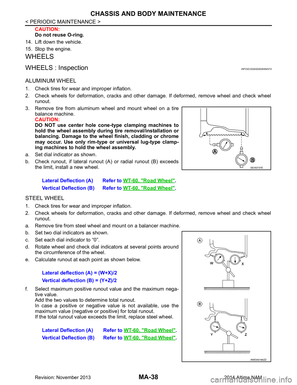
a. Set dial indicator as shown.
b. Check runout, if lateral runout (A) or radial runout (B) exceeds the limit, install a new wheel.
STEEL WHEEL
1. Check tires for wear and improper inflation.
2. Check wheels for deformation, cracks and other dam age. If deformed, remove wheel and check wheel
runout.
a. Remove tire from steel wheel and mount on a balancer machine.
b. Set two dial indicators as shown.
c. Set each dial indicator to “0”.
d. Rotate wheel and check dial indicators at several points around the circumference of the wheel.
e. Calculate runout at each point as shown below.
f. Select maximum positive runout value and the maximum nega- tive value.
Add the two values to determine total runout.
In case a positive or negative value is not available, use the
maximum value (negative or positive) for total runout.
If the total runout value exceeds the limit, replace steel wheel. Lateral Deflection (A) Refer to
WT-60, "Road Wheel"
.
Vertical Deflection (B) Refer to WT-60, "Road Wheel"
.
SEIA0737E
Lateral deflection (A) = (W+X)/2
Vertical deflection (B) = (Y+Z)/2
Lateral Deflection (A) Refer to WT-60, "Road Wheel"
.
Vertical Deflection (B) Refer to WT-60, "Road Wheel"
.
AWEIA0186ZZ
Revision: November 20132014 Altima NAM
Page 3223 of 4801
CHASSIS AND BODY MAINTENANCEMA-39
< PERIODIC MAINTENANCE >
C
D E
F
G H
I
J
K L
M B
MA
N
O A
WHEELS : AdjustmentINFOID:0000000009464575
BALANCING WHEELS (ADH
ESIVE WEIGHT TYPE)
Preparation Before Adjustment
Remove inner and outer balance weights from the r oad wheel. Using releasing agent, remove double-faced
adhesive tape from the road wheel.
CAUTION:
• Be careful not scratch the road wheel during removal.
• After removing double-faced adhesive tape, wipe clean traces of releasing agent from the road
wheel.
Wheel Balance Adjustment
• If a balancer machine has an adhesive weight mode setting, select the adhesive weight mode setting and skip Step 2. below. If a balancer machine only has the clip-on (rim flange) weight mode setting, follow Step 2.
to calculate the correct size adhesive weight.
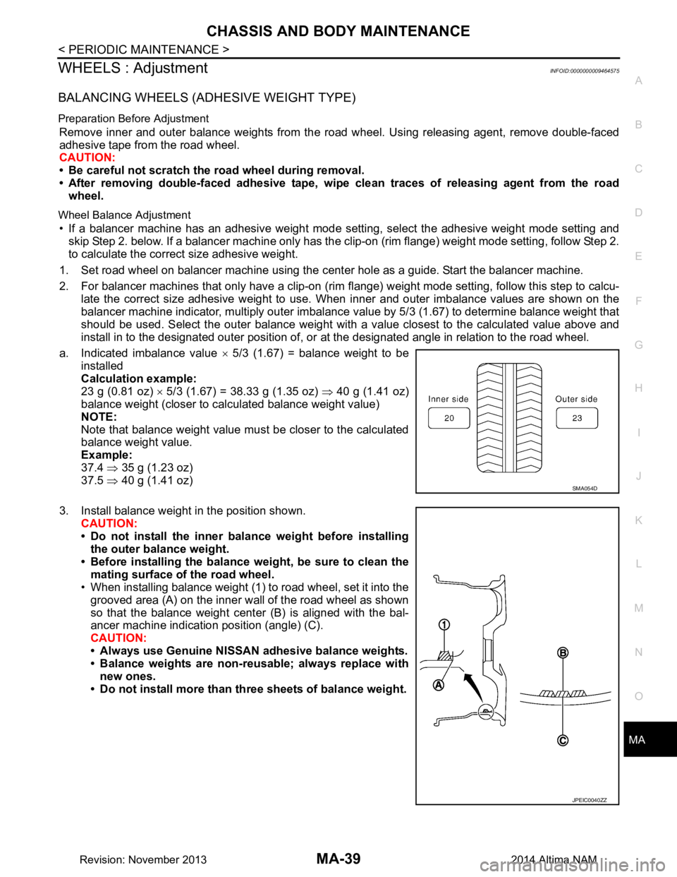
1. Set road wheel on balancer machine using the cent er hole as a guide. Start the balancer machine.
2. For balancer machines that only have a clip-on (rim fl ange) weight mode setting, follow this step to calcu-
late the correct size adhesive weight to use. W hen inner and outer imbalance values are shown on the
balancer machine indicator, multiply outer imbalance value by 5/3 (1.67) to determine balance weight that
should be used. Select the outer balance weight with a value closest to the calculated value above and
install in to the designated outer position of, or at the designated angle in relation to the road wheel.
a. Indicated imbalance value × 5/3 (1.67) = balance weight to be
installed
Calculation example:
23 g (0.81 oz) × 5/3 (1.67) = 38.33 g (1.35 oz) ⇒ 40 g (1.41 oz)
balance weight (closer to calculated balance weight value)
NOTE:
Note that balance weight value must be closer to the calculated
balance weight value.
Example:
37.4 ⇒ 35 g (1.23 oz)
37.5 ⇒ 40 g (1.41 oz)
3. Install balance weight in the position shown. CAUTION:
• Do not install the inner bala nce weight before installing
the outer balance weight.
• Before installing the balance weight, be sure to clean the mating surface of the road wheel.
• When installing balance weight (1) to road wheel, set it into the
grooved area (A) on the inner wall of the road wheel as shown
so that the balance weight cent er (B) is aligned with the bal-
ancer machine indication position (angle) (C).
CAUTION:
• Always use Genuine NISSAN adhesive balance weights.
• Balance weights are non-re usable; always replace with
new ones.
• Do not install more than th ree sheets of balance weight.
SMA054D
JPEIC0040ZZ
Revision: November 20132014 Altima NAM