Page 2545 of 4801
ABBREVIATIONSGI-17
< HOW TO USE THIS MANUAL >
C
D E
F
G H
I
J
K L
M B
GI
N
O P
W
1
2
3
4
5
6
VIN Vehicle identification number
VSS Vehicle speed sensor
ABBREVIATION DESCRIPTION WOT Wide open throttle
ABBREVIATION DESCRIPTION 1
11st range first gear
1
21st range second gear
1GR First gear
ABBREVIATION DESCRIPTION 2
12nd range first gear
2
22nd range second gear
2GR Second gear
2WD 2-wheel drive
ABBREVIATION DESCRIPTION 3GR Third gear
ABBREVIATION DESCRIPTION 4GR Fourth gear
4WAS Four wheel active steer 4WD Four wheel drive
ABBREVIATION DESCRIPTION 5GR Fifth gear
ABBREVIATION DESCRIPTION 6GR Sixth gear
ABBREVIATION DESCRIPTION
Revision: November 20132014 Altima NAMRevision: November 20132014 Altima NAM
Page 2553 of 4801
IDENTIFICATION INFORMATIONGI-25
< VEHICLE INFORMATION >
C
D E
F
G H
I
J
K L
M B
GI
N
O P
VQ35DE
CVT NumberINFOID:0000000009462988
DimensionsINFOID:0000000009462989
Unit:mm (in)
Wheels & TiresINFOID:0000000009462990
Unit:mm (in)
ALAIA0013ZZ
LAIA0074E
Overall length 4863 (191.5)
Overall width 1,830 (72.0)
Overall height QR25DE 1,471 (57.9)
VQ35DE 1,477 (58.1)
Front tread 16” and 17” tires 1,585 (62.4)
18” tires 1,575 (62.0)
Rear tread 16” and 17” tires 1,585 (62.4)
18” tires 1,575 (62.0)
Wheelbase 2,775 (109.3)
Conventional Spare
Road wheel/offset mm (in) 16 X 7.0J Steel/50 (1.97)
16 X 7.0J Cast Aluminum/50 (1.97)
17 X 7.5J Cast Aluminum/50 (1.97)
18 X 7.5J Cast Aluminum/55 (2.17) T135/70D16
Tire size P215/60R16
P215/55R17
P235/45R18
Revision: November 20132014 Altima NAMRevision: November 20132014 Altima NAM
Page 2555 of 4801

PRECAUTIONSGI-27
< PRECAUTION >
C
D E
F
G H
I
J
K L
M B
GI
N
O P
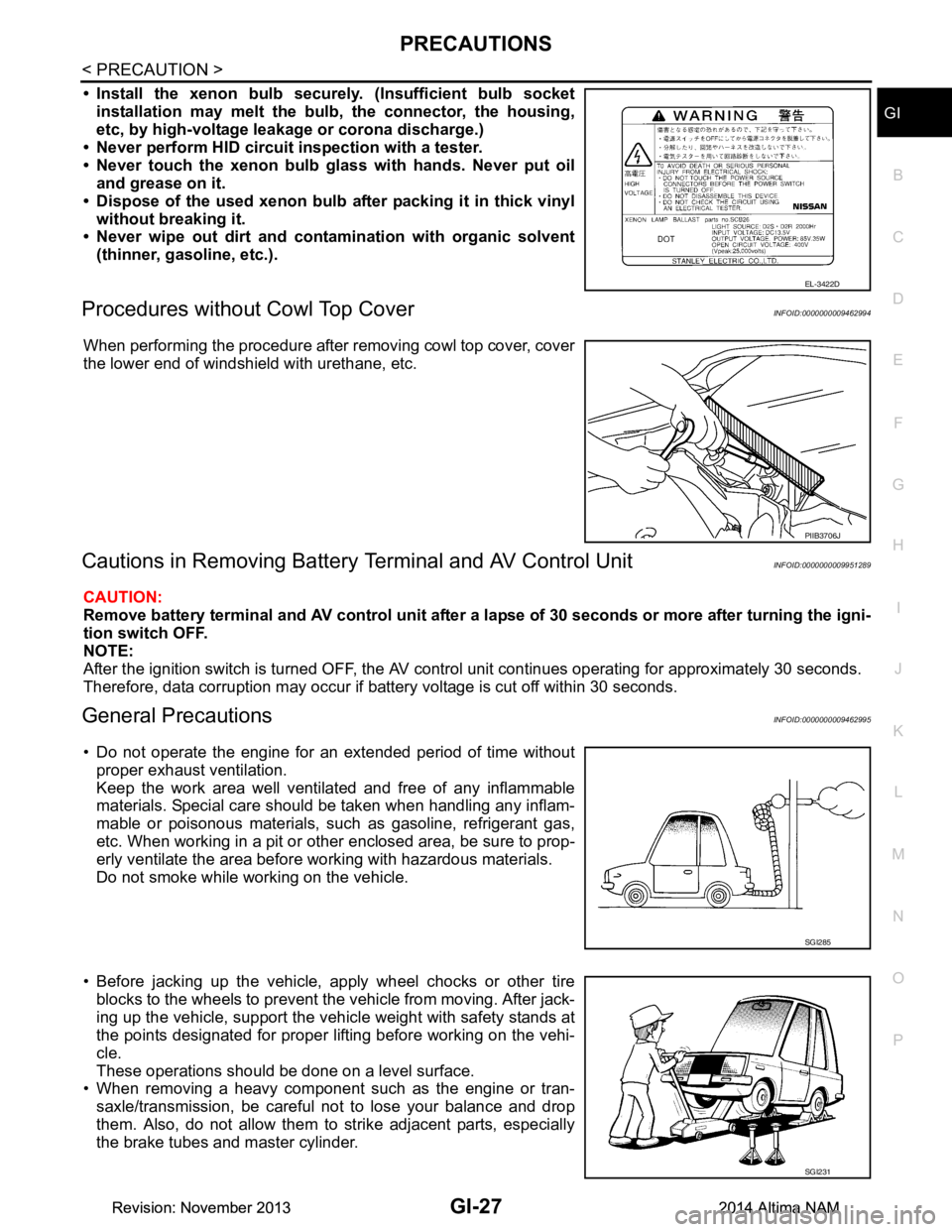
• Install the xenon bulb secure ly. (Insufficient bulb socket
installation may melt the bu lb, the connector, the housing,
etc, by high-voltage leakage or corona discharge.)
• Never perform HID circuit inspection with a tester.
• Never touch the xenon bulb gl ass with hands. Never put oil
and grease on it.
• Dispose of the used xenon bulb after packing it in thick vinyl
without breaking it.
• Never wipe out dirt and contam ination with organic solvent
(thinner, gasoline, etc.).
Procedures without Cowl Top CoverINFOID:0000000009462994
When performing the procedure after removing cowl top cover, cover
the lower end of windshield with urethane, etc.
Cautions in Removing Battery Terminal and AV Control UnitINFOID:0000000009951289
CAUTION:
Remove battery terminal and AV control unit after a lapse of 30 seconds or more after turning the igni-
tion switch OFF.
NOTE:
After the ignition switch is turned OFF, the AV cont rol unit continues operating for approximately 30 seconds.
Therefore, data corruption may occur if battery voltage is cut off within 30 seconds.
General PrecautionsINFOID:0000000009462995
• Do not operate the engine for an extended period of time without proper exhaust ventilation.
Keep the work area well ventilated and free of any inflammable
materials. Special care should be taken when handling any inflam-
mable or poisonous materials, such as gasoline, refrigerant gas,
etc. When working in a pit or ot her enclosed area, be sure to prop-
erly ventilate the area before working with hazardous materials.
Do not smoke while working on the vehicle.
• Before jacking up the vehicle, apply wheel chocks or other tire blocks to the wheels to prevent t he vehicle from moving. After jack-
ing up the vehicle, support the vehicle weight with safety stands at
the points designated for proper lifting before working on the vehi-
cle.
These operations should be done on a level surface.
• When removing a heavy component such as the engine or tran-
saxle/transmission, be careful not to lose your balance and drop
them. Also, do not allow them to strike adjacent parts, especially
the brake tubes and master cylinder.
EL-3422D
PIIB3706J
SGI285
SGI231
Revision: November 20132014 Altima NAMRevision: November 20132014 Altima NAM
Page 2561 of 4801
LIFTING POINTGI-33
< PRECAUTION >
C
D E
F
G H
I
J
K L
M B
GI
N
O P
• Place wheel chocks at both front a nd back of the wheels on the ground.
Garage Jack and Safety StandINFOID:0000000009463005
WARNING:
• Park the vehicle on a level surface when using th e jack. Make sure to avoid damaging pipes, tubes,
etc. under the vehicle.
• Never get under the vehicle while it is supported only by the jack. Always use safety stands when
you have to get under the vehicle.
• Place wheel chocks at both front a nd back of the wheels on the ground.
• Lift at reinforced area of front suspension member where lower control arm attaches, staying in cen-
ter line of wheels.
ALAIA0063ZZ
Revision: November 20132014 Altima NAMRevision: November 20132014 Altima NAM
Page 2564 of 4801

GI-36
< PRECAUTION >
TOW TRUCK TOWING
TOW TRUCK TOWING
Tow Truck TowingINFOID:0000000009463008
CAUTION:
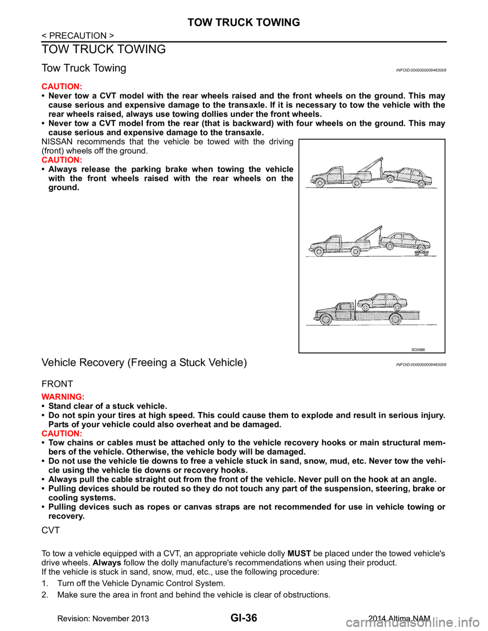
• Never tow a CVT model with the rear wheels raised and the front wheels on the ground. This may
cause serious and expensive damage to the transaxle. If it is necessary to tow the vehicle with the
rear wheels raised, always use towi ng dollies under the front wheels.
• Never tow a CVT model from the rear (that is backw ard) with four wheels on the ground. This may
cause serious and expensive damage to the transaxle.
NISSAN recommends that the vehicle be towed with the driving
(front) wheels off the ground.
CAUTION:
• Always release the parking brake when towing the vehicle with the front wheels raised with the rear wheels on the
ground.
Vehicle Recovery (Freeing a Stuck Vehicle)INFOID:0000000009463009
FRONT
WARNING:
• Stand clear of a stuck vehicle.
• Do not spin your tires at high speed. This could cause them to explode and result in serious injury.
Parts of your vehicle could also overheat and be damaged.
CAUTION:
• Tow chains or cables must be attached only to the vehicle recovery hooks or main structural mem-
bers of the vehicle. Otherwise, the vehicle body will be damaged.
• Do not use the vehicle tie downs to free a vehicle stuck in sand, snow, mud, etc. Never tow the vehi-
cle using the vehicle tie downs or recovery hooks.
• Always pull the cable straight out from the front of the vehicle. Never pull on the hook at an angle.
• Pulling devices should be routed so they do not touch any part of the suspension, steering, brake or
cooling systems.
• Pulling devices such as ropes or canvas straps ar e not recommended for use in vehicle towing or
recovery.
CVT
To tow a vehicle equipped with a CVT, an appropriate vehicle dolly MUST be placed under the towed vehicle's
drive wheels. Always follow the dolly manufacture's recommendations when using their product.
If the vehicle is stuck in sand, snow , mud, etc., use the following procedure:
1. Turn off the Vehicle Dynamic Control System.
2. Make sure the area in front and behind the vehicle is clear of obstructions.
SGI986
Revision: November 20132014 Altima NAMRevision: November 20132014 Altima NAM
Page 2565 of 4801
TOW TRUCK TOWINGGI-37
< PRECAUTION >
C
D E
F
G H
I
J
K L
M B
GI
N
O P
3. Turn the steering wheel right and left to clear an area around the front tires.
4. Slowly rock the vehicle forward and backward. Shift back and forth between R (reverse) and D (drive).
Apply the accelerator as little as possible to maintain the rocking motion.
Release the accelerator pedal before shifting between R and D.
Do not spin the tires above 35 m.p.h. (55 km/h).
5. If the vehicle can not be freed after a few tries, cont act a professional towing service to remove the vehi-
cle.
Revision: November 20132014 Altima NAMRevision: November 20132014 Altima NAM
Page 2678 of 4801
![NISSAN TEANA 2014 Service Manual
A/C AUTO AMP.HAC-29
< ECU DIAGNOSIS INFORMATION > [AUTOMATIC AIR CONDITIONER]
C
D E
F
G H
J
K L
M A
B
HAC
N
O P
Te r m i n a l N o . (Wire color) Description
ConditionVa l u e
(Approx.)
+ − Sign NISSAN TEANA 2014 Service Manual
A/C AUTO AMP.HAC-29
< ECU DIAGNOSIS INFORMATION > [AUTOMATIC AIR CONDITIONER]
C
D E
F
G H
J
K L
M A
B
HAC
N
O P
Te r m i n a l N o . (Wire color) Description
ConditionVa l u e
(Approx.)
+ − Sign](/manual-img/5/57390/w960_57390-2677.png)
A/C AUTO AMP.HAC-29
< ECU DIAGNOSIS INFORMATION > [AUTOMATIC AIR CONDITIONER]
C
D E
F
G H
J
K L
M A
B
HAC
N
O P
Te r m i n a l N o . (Wire color) Description
ConditionVa l u e
(Approx.)
+ − Signal name Input/
Output
1
(L) —CAN-H Input/
Output ——
2
(B) —Ground — — —
3
(SB) Ground Battery power supply Input Ignition switch OFF Battery voltage
4
(BR) Ground TX FR Output Ignition switch ON 0 – 5 V
7
(L) Ground Ambient sensor signal Input Ignition switch ON 0 – 4.8 V
Output voltage varies with ambi- ent temperature
8
*1
(BR) Ground
Heated steering wheel
switch signal InputIgnition
switch ON Heated steer-
ing wheel
switch: While
pressing 0 V
Other than the
above 12 V
9
(G) Ground Sunload sensor signal Input Ignition switch ON 0 – 4.8 V
Output voltage varies with sun- load amount
13
(P) Ground IGN 2 Input Ignition switch ON Battery voltage
15
(Y) Ground RR DEF switch Output Defroster
switch OFF 0 V
ON 12 V
16
(G) Ground Each door motor LIN signal
Input/
Output Ignition switch ON
17
(W) GroundEach door motor power
supply Output Ignition switch ON 12 V
18
(P) Ground
Front blower motor control
signal Output• Ignition switch ON
• Front fan speed: 1st
speed (manual)
20
*1
(P) Ground
Heated steering wheel relay
control signal OutputIgnition
switch ON Within 30 sec-
onds after
turning ON
the heated
steering
switch. 0 V
Other than the
above 12 V
21
(P) —CAN-L Input/
Output ——
SJIA1453J
JSIIA0096ZZ
Revision: November 20132014 Altima NAMRevision: November 20132014 Altima NAM
Page 2679 of 4801
![NISSAN TEANA 2014 Service Manual
HAC-30
< ECU DIAGNOSIS INFORMATION >[AUTOMATIC AIR CONDITIONER]
A/C AUTO AMP.
*1: With heated steering wheel
DTC Inspection Priority ChartINFOID:0000000009463105
If some DTCs are displayed at the sam NISSAN TEANA 2014 Service Manual
HAC-30
< ECU DIAGNOSIS INFORMATION >[AUTOMATIC AIR CONDITIONER]
A/C AUTO AMP.
*1: With heated steering wheel
DTC Inspection Priority ChartINFOID:0000000009463105
If some DTCs are displayed at the sam](/manual-img/5/57390/w960_57390-2678.png)
HAC-30
< ECU DIAGNOSIS INFORMATION >[AUTOMATIC AIR CONDITIONER]
A/C AUTO AMP.
*1: With heated steering wheel
DTC Inspection Priority ChartINFOID:0000000009463105
If some DTCs are displayed at the same time, perfo
rm inspections one by one based on the following priority
chart.
22
(B) —Ground — — —
23
(G) Ground Ignition power supply Input Ignition switch ON Battery voltage
24
(V) Ground RX FR Input Ignition switch ON 0 – 5 V
26
(W) — Sensor ground — — —
27
(G) Ground In-vehicle sensor signal Input Ignition switch ON 0 – 4.8 V
Output voltage varies with in-vehi-
cle temperature
28
(P) Ground Intake sensor signal Input Ignition switch ON 0 – 4.8 V
Output voltage varies with front evaporator fin temperature
35
(P) Ground RR DEF feedback Input
Defroster
switch OFF 0 V
ON 12 V
37
(B) — ACTR Ground — — —
40
(G) Ground
ECV (electrical control
valve) control signal Output• Ignition switch ON
• Active test (HVAC test):
MODE 1
Te r m i n a l N o .
(Wire color) Description
ConditionVa l u e
(Approx.)
+ − Signal name Input/
Output
SJIA1607E
Revision: November 20132014 Altima NAMRevision: November 20132014 Altima NAM