2014 NISSAN TEANA wheel
[x] Cancel search: wheelPage 3224 of 4801
MA-40
< PERIODIC MAINTENANCE >
CHASSIS AND BODY MAINTENANCE
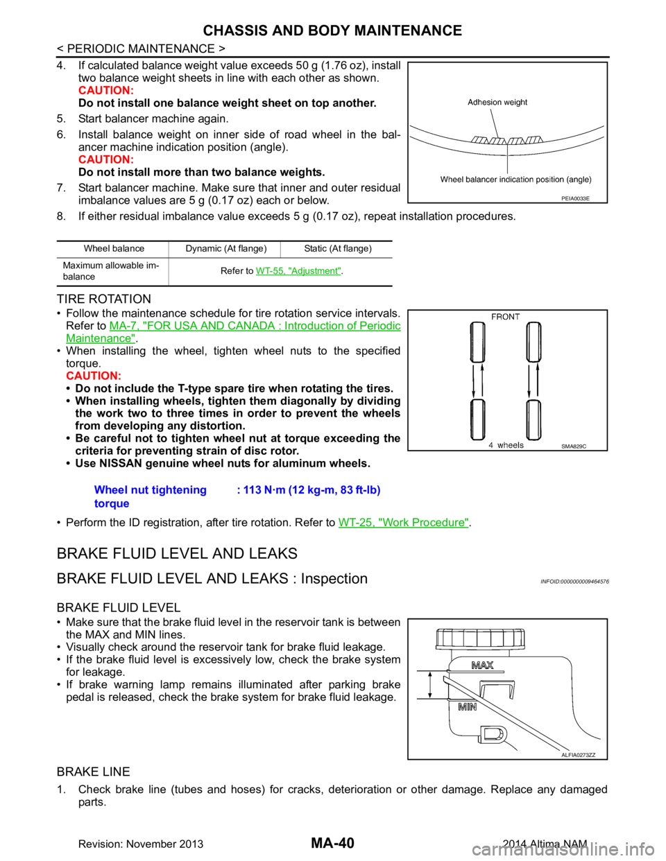
4. If calculated balance weight value exceeds 50 g (1.76 oz), installtwo balance weight sheets in line with each other as shown.
CAUTION:
Do not install one balance weight sheet on top another.
5. Start balancer machine again.
6. Install balance weight on inner side of road wheel in the bal- ancer machine indication position (angle).
CAUTION:
Do not install more than two balance weights.
7. Start balancer machine. Make sure that inner and outer residual imbalance values are 5 g (0.17 oz) each or below.
8. If either residual imbalance value exceeds 5 g (0.17 oz), repeat installation procedures.
TIRE ROTATION
• Follow the maintenance schedule for tire rotation service intervals.
Refer to MA-7, "FOR USA AND CANADA : Introduction of Periodic
Maintenance".
• When installing the wheel, tighten wheel nuts to the specified torque.
CAUTION:
• Do not include the T-type spare tire when rotating the tires.
• When installing wheels, tighten them diagonally by dividing
the work two to three times in order to prevent the wheels
from developing any distortion.
• Be careful not to tighten wheel nut at torque exceeding the criteria for preventing strain of disc rotor.
• Use NISSAN genuine wheel nuts for aluminum wheels.
• Perform the ID registration, after tire rotation. Refer to WT-25, "Work Procedure"
.
BRAKE FLUID LEVEL AND LEAKS
BRAKE FLUID LEVEL AND LEAKS : InspectionINFOID:0000000009464576
BRAKE FLUID LEVEL
• Make sure that the brake fluid level in the reservoir tank is between
the MAX and MIN lines.
• Visually check around the reservoir tank for brake fluid leakage.
• If the brake fluid level is excessively low, check the brake system for leakage.
• If brake warning lamp remains illuminated after parking brake
pedal is released, check the brake system for brake fluid leakage.
BRAKE LINE
1. Check brake line (tubes and hoses) for cracks, deterioration or other damage. Replace any damaged
parts.
Wheel balance Dynamic (At flange) Static (At flange)
Maximum allowable im-
balance Refer to
WT-55, "Adjustment"
.
PEIA0033E
Wheel nut tightening
torque : 113 N·m (12 kg-m, 83 ft-lb)
SMA829C
ALFIA0273ZZ
Revision: November 20132014 Altima NAM
Page 3228 of 4801
MA-44
< PERIODIC MAINTENANCE >
CHASSIS AND BODY MAINTENANCE
POWER STEERING FLUID AND LINES : Inspection
INFOID:0000000009464588
FLUID LEVEL
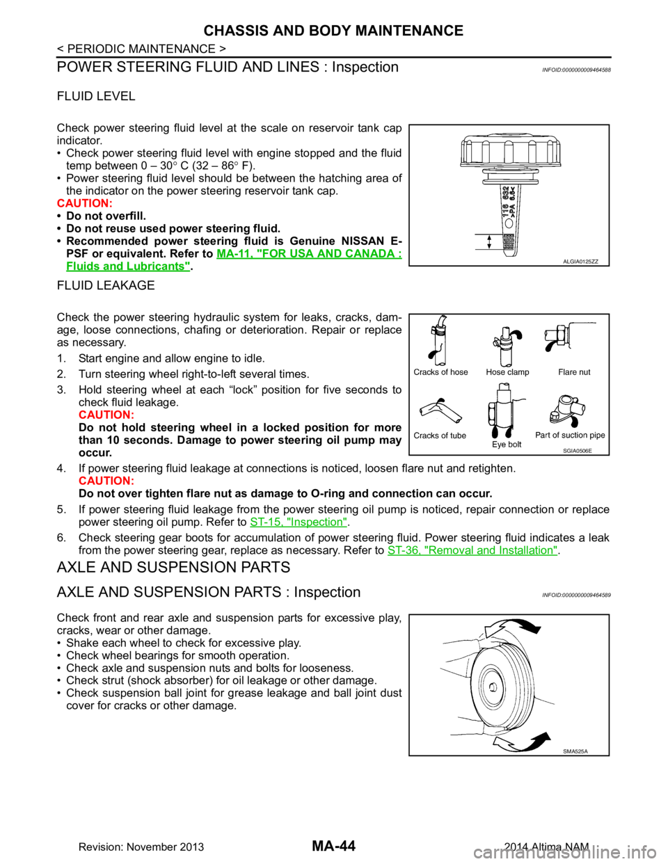
Check power steering fluid level at the scale on reservoir tank cap
indicator.
• Check power steering fluid level with engine stopped and the fluid temp between 0 – 30 ° C (32 – 86 ° F).
• Power steering fluid level should be between the hatching area of the indicator on the power steering reservoir tank cap.
CAUTION:
• Do not overfill.
• Do not reuse used power steering fluid.
• Recommended power steering fluid is Genuine NISSAN E-
PSF or equivalent. Refer to MA-11, "FOR USA AND CANADA :
Fluids and Lubricants".
FLUID LEAKAGE
Check the power steering hydraulic system for leaks, cracks, dam-
age, loose connections, chafing or det erioration. Repair or replace
as necessary.
1. Start engine and allow engine to idle.
2. Turn steering wheel right-to-left several times.
3. Hold steering wheel at each “lock” position for five seconds to check fluid leakage.
CAUTION:
Do not hold steering wheel in a locked position for more
than 10 seconds. Damage to power steering oil pump may
occur.
4. If power steering fluid leakage at connections is noticed, loosen flare nut and retighten.
CAUTION:
Do not over tighten flare nut as damage to O-ring and connection can occur.
5. If power steering fluid leakage from the power steer ing oil pump is noticed, repair connection or replace
power steering oil pump. Refer to ST-15, "Inspection"
.
6. Check steering gear boots for accumulation of power steering fluid. Power steering fluid indicates a leak from the power steering gear, replace as necessary. Refer to ST-36, "Removal and Installation"
.
AXLE AND SUSPENSION PARTS
AXLE AND SUSPENSION PARTS : InspectionINFOID:0000000009464589
Check front and rear axle and suspension parts for excessive play,
cracks, wear or other damage.
• Shake each wheel to check for excessive play.
• Check wheel bearings for smooth operation.
• Check axle and suspension nuts and bolts for looseness.
• Check strut (shock absorber) for oil leakage or other damage.
• Check suspension ball joint for grease leakage and ball joint dust cover for cracks or other damage.
ALGIA0125ZZ
SGIA0506E
SMA525A
Revision: November 20132014 Altima NAM
Page 3325 of 4801

MWI-70
< DTC/CIRCUIT DIAGNOSIS >
STEERING SWITCH
STEERING SWITCH
DescriptionINFOID:0000000009461735
When one of the steering switches is pushed, the resistance in the steering switch changes the signal to
identify which button is controlling the information display.
Diagnosis ProcedureINFOID:0000000009461736
Regarding Wiring Diagram information, refer to MWI-32, "Wiring Diagram".
1.CHECK STEERING SWITCH CIRCUIT
1. Turn ignition switch OFF.
2. Disconnect combination meter harness connector M24 and spiral cable harness connector M30.
3. Check continuity between combination meter har ness connector M24 and spiral cable harness connector
M30.
4. Check continuity between combination meter harness connector M24 and ground.
Is the inspection results normal?
YES >> Inspection End.
NO >> Repair or replace harness or connectors.
Component InspectionINFOID:0000000009461737
1.CHECK STEERING SWITCH RESISTANCE
Check resistance between the following steering switch terminals.
Is the inspection results normal?
YES >> GO TO 2.
NO >> Replace steering wheel switch. Refer to AV-51, "Removal and Installation"
.
Combination meter Spiral cable
Continuity
Connector Terminal Connector Terminal
M24 3
M30 24
Ye s
431
24 33
Combination meter GroundContinuity
Connector Terminal
M24 3
No
4
24
Terminal Signal name Condition Resistance (
Ω)
(Approx.)
14
17 Display Depress DISPLAY switch.
�†2023
Back Depress BACK switch. 723
15 Enter Depress ENTER switch. 2023
Menu Up Depress ENTER switch up. 121
Menu Down Depress ENTER switch down. 321
Revision: November 20132014 Altima NAMRevision: November 20132014 Altima NAM
Page 3342 of 4801
PB-4
< BASIC INSPECTION >
PARKING BRAKE SYSTEM
BASIC INSPECTION
PARKING BRAKE SYSTEM
InspectionINFOID:0000000009462912
PEDAL STROKE
1. Operate parking brake pedal with a force of 196 N (20.0 kg-f, 44.1 lb-f), make sure pedal stroke is within
the specified number of notches. (Check it by listening and counting ratchet clicks.)
2. When brake warning lamp turns ON, check that the pedal stroke is within the specified number of notches. (Check it by listening to the clicks of the ratchet.)
INSPECT COMPONENTS
• Make sure that the mounting conditions (loosenes s, backlash, etc.) of each component are normal.
• Check the following:
- Device assembly for bend, damage and cracks. Replace if necessary.
- Cables and equalizer for wear and damage. Replace if necessary.
- Parking brake switch. Replace if necessary.
AdjustmentINFOID:0000000009462913
ADJUSTMENT
1. Remove rear wheel and tire using power tool. Refer to WT-55, "Adjustment".
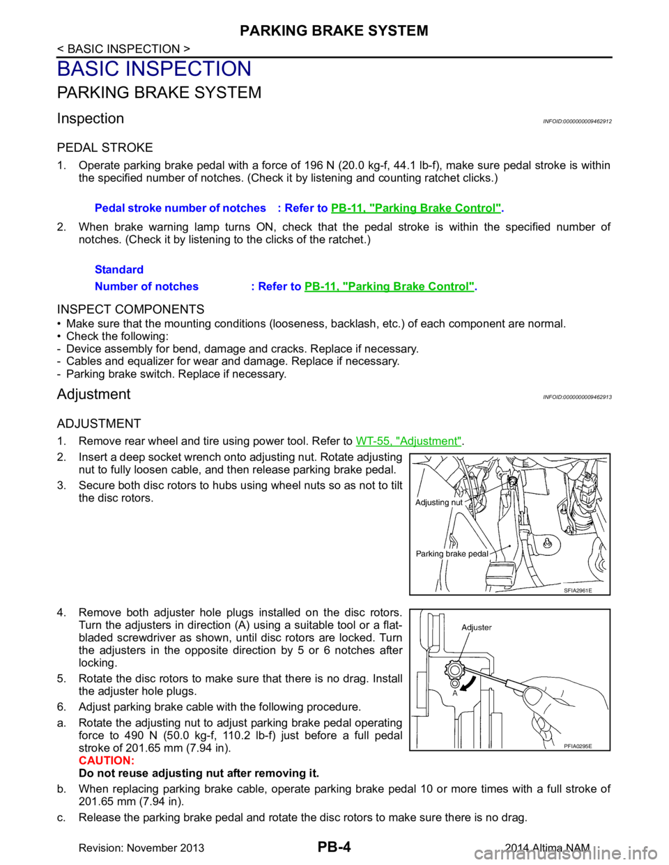
2. Insert a deep socket wrench onto adjusting nut. Rotate adjusting nut to fully loosen cable, and then release parking brake pedal.
3. Secure both disc rotors to hubs using wheel nuts so as not to tilt the disc rotors.
4. Remove both adjuster hole plugs installed on the disc rotors. Turn the adjusters in direction (A) using a suitable tool or a flat-
bladed screwdriver as shown, until disc rotors are locked. Turn
the adjusters in the opposite direction by 5 or 6 notches after
locking.
5. Rotate the disc rotors to make sure that there is no drag. Install the adjuster hole plugs.
6. Adjust parking brake cable with the following procedure.
a. Rotate the adjusting nut to adjust parking brake pedal operating force to 490 N (50.0 kg-f, 110.2 lb-f) just before a full pedal
stroke of 201.65 mm (7.94 in).
CAUTION:
Do not reuse adjusting nut after removing it.
b. When replacing parking brake cable, operate parking brake pedal 10 or more times with a full stroke of 201.65 mm (7.94 in).
c. Release the parking brake pedal and rotate the disc rotors to make sure there is no drag. Pedal stroke number of notches : Refer to
PB-11, "Parking Brake Control"
.
Standard
Number of notches : Refer to PB-11, "Parking Brake Control"
.
SFIA2961E
PFIA0295E
Revision: November 20132014 Altima NAM
Page 3343 of 4801
PARKING BRAKE SYSTEMPB-5
< BASIC INSPECTION >
C
D E
G H
I
J
K L
M A
B
PB
N
O P
d. Rotate the adjusting nut to adjust the parking brak e pedal force to 196 N (20.0 kg-f, 44.1 lb-f) when the
parking brake pedal stroke is within the specified number of notches. (check it by listening and counting
the ratchet clicks).
e. After adjustment, check that there is no drag with the parking brake pedal is being released. If drag exists,
perform the following:
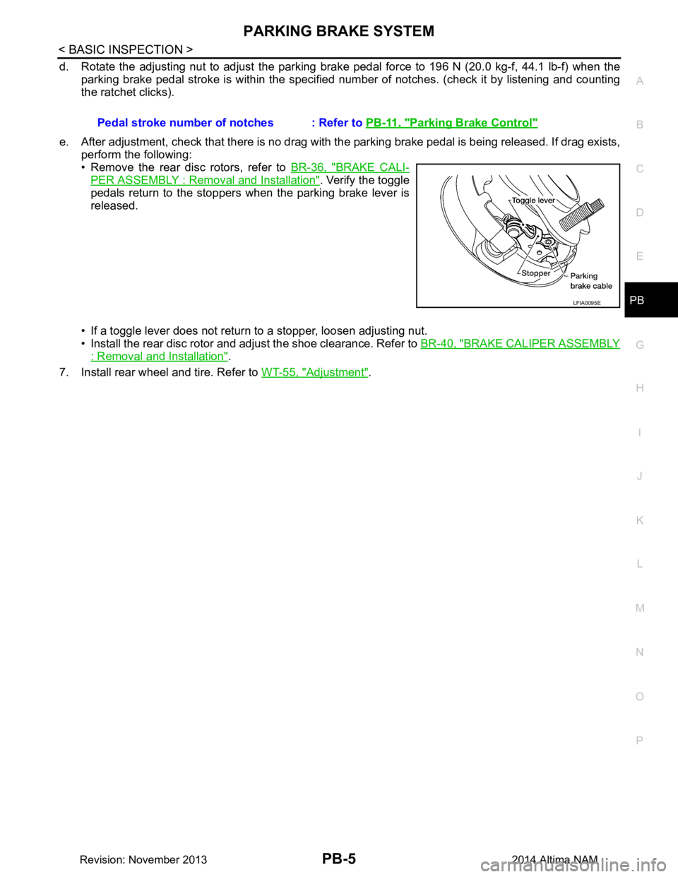
• Remove the rear disc rotors, refer to BR-36, "BRAKE CALI-
PER ASSEMBLY : Removal and Installation". Verify the toggle
pedals return to the stoppers when the parking brake lever is
released.
• If a toggle lever does not return to a stopper, loosen adjusting nut.
• Install the rear disc rotor and adjust the shoe clearance. Refer to BR-40, "BRAKE CALIPER ASSEMBLY
: Removal and Installation".
7. Install rear wheel and tire. Refer to WT-55, "Adjustment"
.
Pedal stroke number of notches : Refer to
PB-11, "Parking Brake Control"
LFIA0095E
Revision: November 20132014 Altima NAM
Page 3345 of 4801
PARKING BRAKE CONTROLPB-7
< REMOVAL AND INSTALLATION >
C
D E
G H
I
J
K L
M A
B
PB
N
O P
REMOVAL AND INSTALLATION
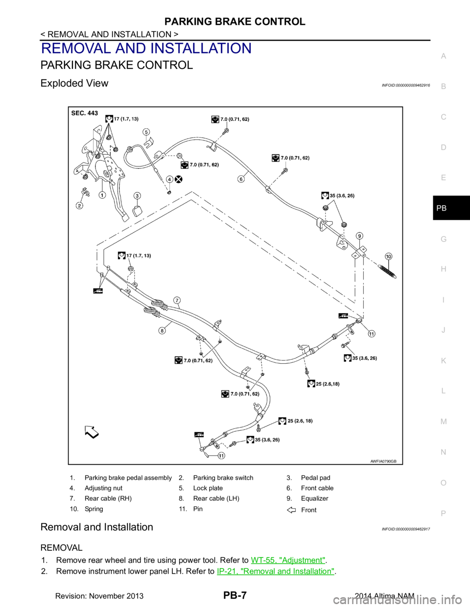
PARKING BRAKE CONTROL
Exploded ViewINFOID:0000000009462916
Removal and InstallationINFOID:0000000009462917
REMOVAL
1. Remove rear wheel and tire using power tool. Refer to WT-55, "Adjustment".
2. Remove instrument lower panel LH. Refer to IP-21, "Removal and Installation"
.
1. Parking brake pedal assembly 2. Parking brake switch 3. Pedal pad
4. Adjusting nut 5. Lock plate 6. Front cable
7. Rear cable (RH) 8. Rear cable (LH) 9. Equalizer
10. Spring 11. Pin Front
AWFIA0790GB
Revision: November 20132014 Altima NAM
Page 3347 of 4801
PARKING BRAKE SHOEPB-9
< REMOVAL AND INSTALLATION >
C
D E
G H
I
J
K L
M A
B
PB
N
O P
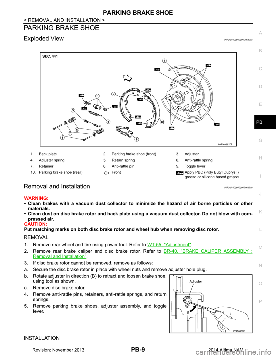
PARKING BRAKE SHOE
Exploded ViewINFOID:0000000009462918
Removal and InstallationINFOID:0000000009462919
WARNING:
• Clean brakes with a vacuum dust co llector to minimize the hazard of air borne particles or other
materials.
• Clean dust on disc brake rotor and back plate usin g a vacuum dust collector. Do not blow with com-
pressed air.
CAUTION:
Put matching marks on both disc brake rotor and wheel hub when removing disc rotor.
REMOVAL
1. Remove rear wheel and tire using power tool. Refer to WT-55, "Adjustment".
2. Remove rear brake caliper and disc brake rotor. Refer to BR-40, "BRAKE CALIPER ASSEMBLY :
Removal and Installation".
3. If disc brake rotor cannot be removed, remove as follows:
a. Secure the disc brake rotor in place with wheel nuts and remove adjuster hole plug.
b. Rotate adjuster in direction (B) to retract and loosen brake shoe, using tool as shown.
c. Remove disc brake rotor.
4. Remove anti-rattle pins, retainers, anti-rattle springs, and return springs.
5. Remove parking brake shoes, adjuster assembly, and toggle lever.
INSTALLATION
1. Back plate 2. Parking brake shoe (front) 3. Adjuster
4. Adjuster spring 5. Return spring 6. Anti-rattle spring
7. Retainer 8. Anti-rattle pin 9. Toggle lever
10. Parking brake shoe (rear) Front Apply PBC (Poly Butyl Cuprysil) grease or silicone based grease
AWFIA0883ZZ
PFIA0309E
Revision: November 20132014 Altima NAM
Page 3474 of 4801

PG-42
< DTC/CIRCUIT DIAGNOSIS >
HARNESS
B3 M51 L/8 : Heated steering wheel switch D2 M153 W / 2 4: AV control unit (With navigation system
with BOSE audio system)
C3 M52 W/2 : Combination switch (Spiral cable) A3 M155 W/4 : Joint connector-M06
C3 M53 W/8 : Steering angle sensor C3 M156 W/4 : Joint connector-M07
D2 M54 W/4 : Hazard switch D3 M157 W/4 : Joint connector-M08
A1 M55 BR/2 : Front speaker LH B3 M158 W/8 : Meter control switch
B1 M56 B/2 : Sunload sensor D1 M159 W/4 : Dongle unit
B2 M57 — : Body ground Console sub-harness
E3 M58 W/40 : ITS control unit D4 M201 W/6 : Front heated seat switch LH
E3 M59 W/32 : ITS control unit E4 M202 BR/6 : Front heated seat switch RH
F2 M60 O/2 : Front passenger air bag module D4 M204 BR/2 : CVT shift selector
F1 M61 — : Body ground E3 M205 W / 1 6 : T o M 1 6
B3 M62 GR/8 : Warning system switch D5 M209 GR/3 : Front console power socket
F1 M63 BR/2 : Front speaker RH Speaker sub-harness
A3 M64 W/4 : Joint connector-M01 D1 M300 W / 2 : T o M 5 0
F1 M66 W/3 : Optical sensor D1 M301 BR/2 : Center speaker
Revision: November 20132014 Altima NAM