2014 NISSAN TEANA Center
[x] Cancel search: CenterPage 3726 of 4801
REAR SUSPENSION ASSEMBLYRSU-9
< UNIT REMOVAL AND INSTALLATION >
C
D
F
G H
I
J
K L
M A
B
RSU
N
O P
2. Remove the brake caliper torque member bolts, l eaving the brake hose attached. Reposition the brake
caliper aside with wire. Refer to BR-39, "BRAKE CALIPER ASSEMBLY : Exploded View"
.
CAUTION:
• Do not depress brake pedal while brake caliper assembly is removed.
• Do not twist or stretch the brake hose.
3. Put alignment marks on the disc brake rotor and rear hub and bearing assembly, then remove the disc brake rotor.
4. Disconnect parking brake cables from each knuckle. Refer to PB-9, "Exploded View"
.
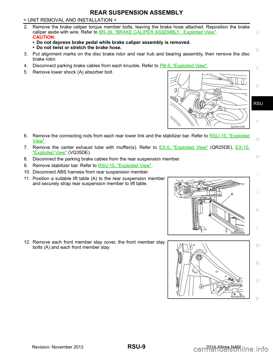
5. Remove lower shock (A) absorber bolt.
6. Remove the connecting rods from each rear lower link and the stabilizer bar. Refer to RSU-15, "Exploded
View".
7. Remove the center exhaust tube with muffler(s). Refer to EX-5, "Exploded View"
(QR25DE), EX-10,
"Exploded View" (VQ35DE).
8. Disconnect the parking brake cables from the rear suspension member.
9. Remove stabilizer bar. Refer to RSU-15, "Exploded View"
.
10. Disconnect ABS harness from rear suspension member.
11. Position a suitable lift table (A) to the rear suspension member and securely strap rear suspension member to lift table.
12. Remove each front member stay cover, the front member stay bolts (A) and each front member stay.
ALEIA0157ZZ
ALEIA0160ZZ
ALEIA0161ZZ
Revision: November 20132014 Altima NAM
Page 3740 of 4801
COMPONENT INSPECTIONSB-5
< BASIC INSPECTION >
C
D E
F
G
I
J
K L
M A
B
SB
N
O P
BASIC INSPECTION
COMPONENT INSPECTION
InspectionINFOID:0000000009462960
AFTER A COLLISION
WARNING:
Inspect all seat belt assemblies in cluding retractors and attaching hardware after any collision.
NISSAN/INFINITI recommends that all seat belt assemblies in use during a collision be replaced
unless the collision was minor and th e belts show no damage and continue to operate properly. Fail-
ure to do so could result in serious personal inju ry in an accident. Seat belt assemblies not in use dur-
ing a collision should also be replaced if either da mage or improper operation is noted. Seat belt pre-
tensioners should be replaced even if the seat belts are not in use during a frontal collision in which
the air bags are deployed.
Replace any seat belt assembly (including anchor bolts) if:
• The seat belt was in use at the time of a collision (except for minor collisions and the belts, retractors and
buckles show no damage and continue to operate properly).
• The seat belt was damaged in an accident (i.e. torn webbing, bent retractor or guide, etc.).
• The seat belt attaching point is damaged in an accident . Inspect the seat belt attaching area for damage or
distortion and repair if necessary before installing a new seat belt assembly.
• Anchor bolts are deformed or worn out.
• The seat belt pre-tensioner should be replaced even if t he seat belts are not in use during the collision in
which the air bags are deployed.
PRELIMINARY CHECKS
1. Check the seat belt warning lamp for proper operation per the following:
a. Turn ignition switch ON. The seat belt warning lamp should illuminate.
b. Fasten driver seat belt. The seat belt warning lamp should turn OFF.
2. If the air bag warning lamp is blinking, perform self-diagnosis with CONSULT and air bag warning lamp. Refer to SRC-17, "Trouble Diagnosis without CONSULT"
.
3. Check that the seat belt retractor, seat belt anchor and buckle bolts are tightened firmly.
4. Check the shoulder seat belt guide and shoulder belt height adjuster for front seats. Check that guide
swivels freely and that webbing lays flat and does not bind in guide. Check that height adjuster operates
properly and holds securely.
5. Check retractor operation:
a. Fully extend the seat belt webbing and check for twists, tears or other damage.
b. Allow the seat belt to retract. Check that webbing retu rns smoothly and completely into the retractor. If the
seat belt does not return smoothly, wipe the inside of t he loops with a clean paper cloth. Dirt build-up in the
loops of the upper anchors can cause t he seat belts to retract slowly.
c. Fasten the seat belt. Check that seat belt returns sm oothly and completely to the retractor. If the webbing
does not return smoothly, the cause may be an accu mulation of dust or dirt. Use the “SEAT BELT TAPE
SET” and perform the following steps.
d. Inspect the front seat belt D-ring anchor 1. Pull the seat belt out to a length of 500 mm (19.69 in) or more.
2. Hold the seat belt at the center pillar webbing opening with a clip or other device.
3. Pass a thin wire through the D-ring anchor webbing opening. Hold both ends of the wire and pull it tightly while moving it up and down several times along the webbing opening surface to remove dirt
stuck there.
4. Any dirt that cannot be removed with the wire can be removed by cleaning the opening with a clean
cloth.
5. Apply tape at the point where the webbing contacts the D-ring anchor webbing opening. NOTE:
Apply the tape so that there is no slack or wrinkling.
6. Remove the clip holding the seat belt and check that the webbing returns smoothly.
6. Repeat steps above if necessary to check the other seat belts.
Revision: November 20132014 Altima NAM
Page 3744 of 4801
FRONT SEAT BELTSB-9
< REMOVAL AND INSTALLATION >
C
D E
F
G
I
J
K L
M A
B
SB
N
O P
2. Disconnect both negative and positive battery terminals, then wait at least three minutes. Refer to PG-73,
"Removal and Installation (Battery)".
3. Remove center pillar lower finisher. Refer to INT-23, "CENTER PILLAR LOWER FINISHER : Removal
and Installation".
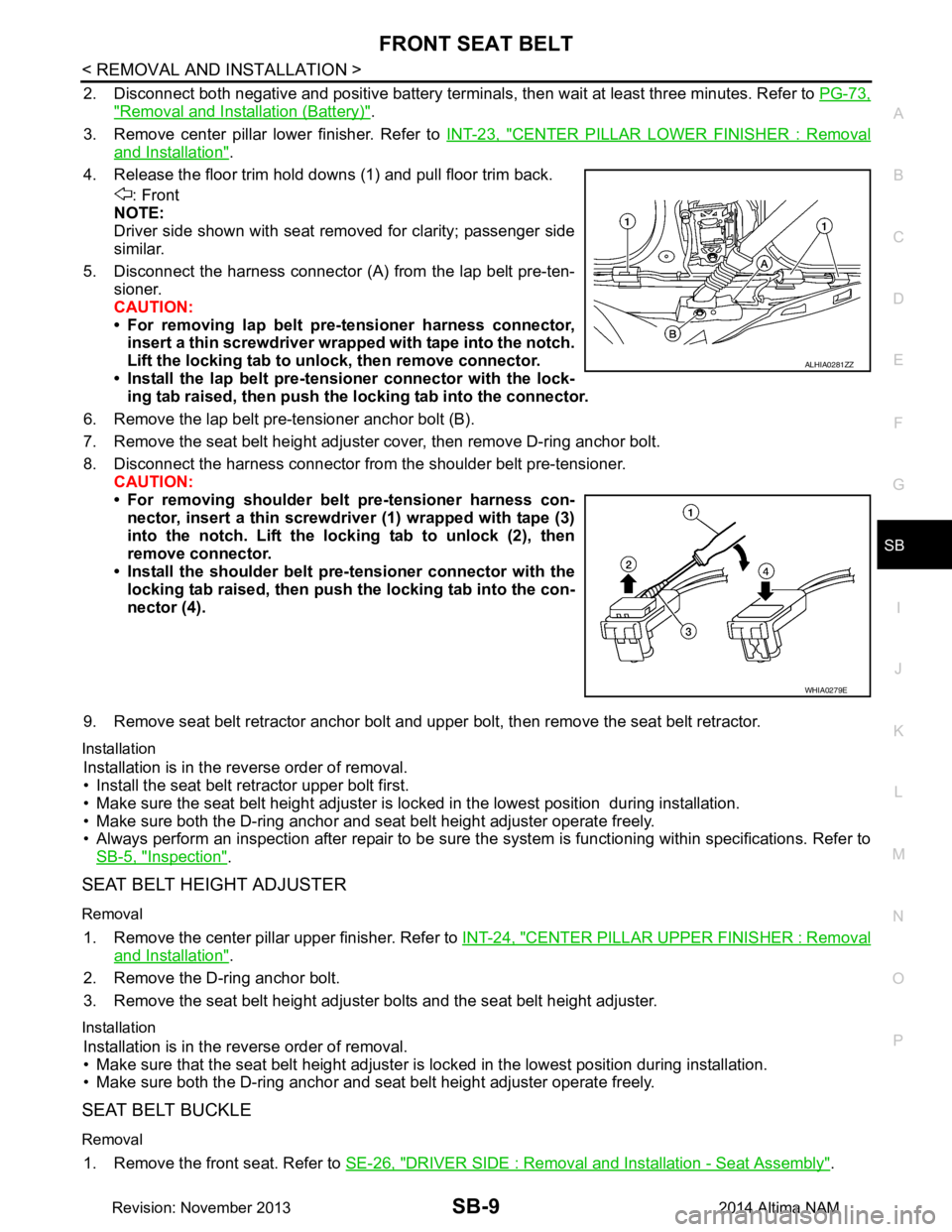
4. Release the floor trim hold downs (1) and pull floor trim back. : Front
NOTE:
Driver side shown with seat removed for clarity; passenger side
similar.
5. Disconnect the harness connector (A ) from the lap belt pre-ten-
sioner.
CAUTION:
• For removing lap belt pre-tensioner harness connector, insert a thin screwdriver wrappe d with tape into the notch.
Lift the locking tab to un lock, then remove connector.
• Install the lap belt pre-tensioner connector with the lock- ing tab raised, then push the locking tab into the connector.
6. Remove the lap belt pre-tensioner anchor bolt (B).
7. Remove the seat belt height adjuster cover, then remove D-ring anchor bolt.
8. Disconnect the harness connector from the shoulder belt pre-tensioner. CAUTION:
• For removing shoulder belt pre-tensioner harness con- nector, insert a thin screwdriver (1) wrapped with tape (3)
into the notch. Lift the lo cking tab to unlock (2), then
remove connector.
• Install the shoulder belt pr e-tensioner connector with the
locking tab raised, then push the locking tab into the con-
nector (4).
9. Remove seat belt retractor anchor bolt and upper bolt, then remove the seat belt retractor.
Installation
Installation is in the reverse order of removal.
• Install the seat belt retractor upper bolt first.
• Make sure the seat belt height adjuster is lock ed in the lowest position during installation.
• Make sure both the D-ring anchor and seat belt height adjuster operate freely.
• Always perform an inspection after repair to be sure t he system is functioning within specifications. Refer to
SB-5, "Inspection"
.
SEAT BELT HEIGHT ADJUSTER
Removal
1. Remove the center pillar upper finisher. Refer to INT-24, "CENTER PILLAR UPPER FINISHER : Removal
and Installation".
2. Remove the D-ring anchor bolt.
3. Remove the seat belt height adjuster bolts and the seat belt height adjuster.
Installation
Installation is in the reverse order of removal.
• Make sure that the seat belt height adjuster is locked in the lowest position during installation.
• Make sure both the D-ring anchor and seat belt height adjuster operate freely.
SEAT BELT BUCKLE
Removal
1. Remove the front seat. Refer to SE-26, "DRIVER SIDE : Removal and Installation - Seat Assembly".
ALHIA0281ZZ
WHIA0279E
Revision: November 20132014 Altima NAM
Page 3746 of 4801
REAR SEAT BELTSB-11
< REMOVAL AND INSTALLATION >
C
D E
F
G
I
J
K L
M A
B
SB
N
O P
REAR SEAT BELT
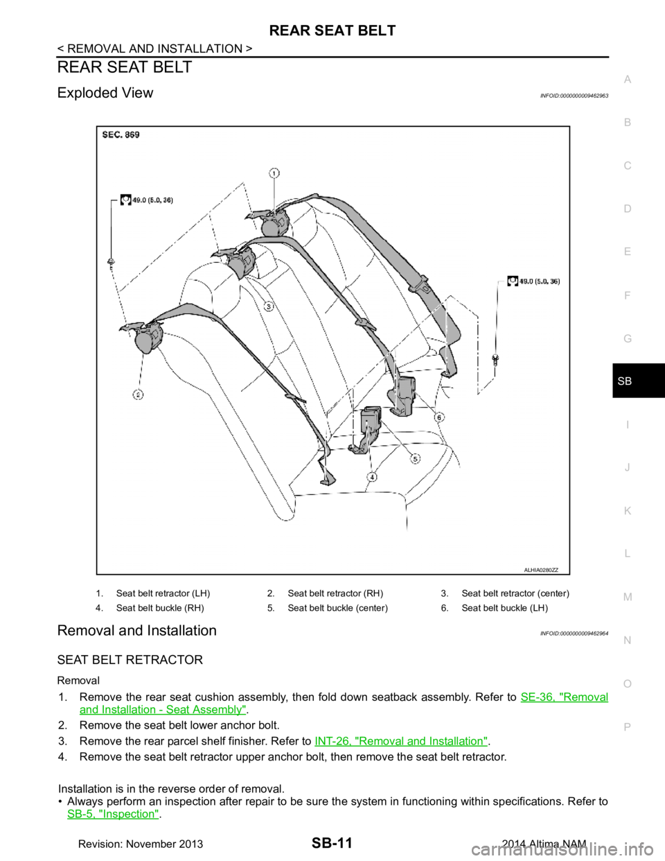
Exploded ViewINFOID:0000000009462963
Removal and InstallationINFOID:0000000009462964
SEAT BELT RETRACTOR
Removal
1. Remove the rear seat cushion assembly, then fold down seatback assembly. Refer to SE-36, "Removal
and Installation - Seat Assembly".
2. Remove the seat belt lower anchor bolt.
3. Remove the rear parcel shelf finisher. Refer to INT-26, "Removal and Installation"
.
4. Remove the seat belt retractor upper anchor bolt, then remove the seat belt retractor.
Installation is in the reverse order of removal.
• Always perform an inspection after repair to be sure t he system in functioning within specifications. Refer to
SB-5, "Inspection"
.
1. Seat belt retractor (LH) 2. Seat belt re tractor (RH) 3. Seat belt retractor (center)
4. Seat belt buckle (RH) 5. Seat belt buckle (center) 6. Seat belt buckle (LH)
ALHIA0280ZZ
Revision: November 20132014 Altima NAM
Page 3768 of 4801
SQUEAK AND RATTLE TROUBLE DIAGNOSESSE-19
< SYMPTOM DIAGNOSIS >
C
D E
F
G H
I
K L
M A
B
SE
N
O P
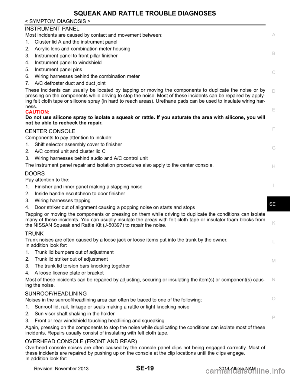
INSTRUMENT PANEL
Most incidents are caused by contact and movement between:
1. Cluster lid A and the instrument panel
2. Acrylic lens and combination meter housing
3. Instrument panel to front pillar finisher
4. Instrument panel to windshield
5. Instrument panel pins
6. Wiring harnesses behind the combination meter
7. A/C defroster duct and duct joint
These incidents can usually be located by tapping or moving the components to duplicate the noise or by
pressing on the components while driving to stop the noi se. Most of these incidents can be repaired by apply-
ing felt cloth tape or silicone spray (in hard to reach areas). Urethane pads can be used to insulate wiring har-
ness.
CAUTION:
Do not use silicone spray to isolate a squeak or ra ttle. If you saturate the area with silicone, you will
not be able to recheck the repair.
CENTER CONSOLE
Components to pay attention to include:
1. Shift selector assembly cover to finisher
2. A/C control unit and cluster lid C
3. Wiring harnesses behind audio and A/C control unit
The instrument panel repair and isolation pr ocedures also apply to the center console.
DOORS
Pay attention to the:
1. Finisher and inner panel making a slapping noise
2. Inside handle escutcheon to door finisher
3. Wiring harnesses tapping
4. Door striker out of alignment causing a popping noise on starts and stops
Tapping or moving the components or pressing on them wh ile driving to duplicate the conditions can isolate
many of these incidents. You can usually insulate the ar eas with felt cloth tape or insulator foam blocks from
the NISSAN Squeak and Rattle Kit (J-50397) to repair the noise.
TRUNK
Trunk noises are often caused by a loose jack or loose items put into the trunk by the owner.
In addition look for:
1. Trunk lid bumpers out of adjustment
2. Trunk lid striker out of adjustment
3. The trunk lid torsion bars knocking together
4. A loose license plate or bracket
Most of these incidents can be repaired by adjusting, se curing or insulating the item(s) or component(s) caus-
ing the noise.
SUNROOF/HEADLINING
Noises in the sunroof/headlining area can often be traced to one of the following:
1. Sunroof lid, rail, linkage or seals making a rattle or light knocking noise
2. Sun visor shaft shaking in the holder
3. Front or rear windshield touching headlining and squeaking
Again, pressing on the components to stop the noise while duplicating the conditions can isolate most of these
incidents. Repairs usually consist of insulating with felt cloth tape.
OVERHEAD CONSOLE (FRONT AND REAR)
Overhead console noises are often caused by the cons ole panel clips not being engaged correctly. Most of
these incidents are repaired by pushing up on the c onsole at the clip locations until the clips engage.
In addition look for:
Revision: November 20132014 Altima NAMRevision: November 20132014 Altima NAM
Page 3781 of 4801
SE-32
< REMOVAL AND INSTALLATION >
FRONT SEAT
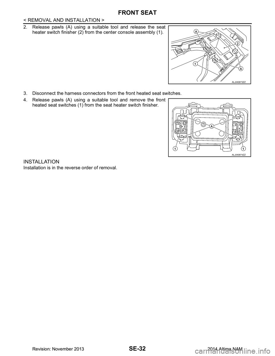
2. Release pawls (A) using a suitable tool and release the seatheater switch finisher (2) from the center console assembly (1).
3. Disconnect the harness connectors from the front heated seat switches.
4. Release pawls (A) using a suitable tool and remove the front heated seat switches (1) from t he seat heater switch finisher.
INSTALLATION
Installation is in the reverse order of removal.
ALJIA0973ZZ
ALJIA0974ZZ
Revision: November 20132014 Altima NAMRevision: November 20132014 Altima NAM
Page 3969 of 4801
COLLISION DIAGNOSISSR-7
< BASIC INSPECTION >
C
D E
F
G
I
J
K L
M A
B
SR
N
O P
For Side and Rollover CollisionINFOID:0000000009463068
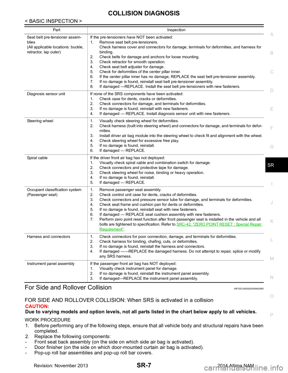
FOR SIDE AND ROLLOVER COLLISION: When SRS is activated in a collision
CAUTION:
Due to varying models and option levels, not all parts listed in the chart below apply to all vehicles.
WORK PROCEDURE
1. Before performing any of the following steps, ensur e that all vehicle body and structural repairs have been
completed.
2. Replace the following components:
- Front seat back assembly (on the side on which side air bag is activated).
- Door finisher (on the side on which door-mounted curtain air bag is activated).
- Pop-up roll bar assemblies and pop-up roll bar covers.
Seat belt pre-tensioner assem-
blies
(All applicable locations: buckle,
retractor, lap outer) If the pre-tensioners have NOT been activated:
1. Remove seat belt pre-tensioners.
Check harness cover and connectors for damage, terminals for deformities, and harness for
binding.
2. Check belts for damage and anchors for loose mounting.
3. Check retractor for smooth operation.
4. Check seat belt adjuster for damage.
5. Check for deformities of the center pillar inner.
6. If the center pillar inner has no damage, REPLACE the seat belt pre-tensioner assembly.
7. If no damage is found, reinstall seat belt pre-tensioner assembly.
8. If damaged —REPLACE. Install the seat belt pre-tensioners with new fasteners.
Diagnosis sensor unit If none of the SRS components have been activated: 1. Check case for dents, cracks or deformities.
2. Check connectors for damage, and terminals for deformities.
3. If no damage is found, reinstall with new fasteners.
4. If damaged — REPLACE. Install diagnosis sensor unit with new fasteners.
Steering wheel 1. Visually check steering wheel for deformities. 2. Check harness (built into steering wheel) and connectors for damage, and terminals for defor-mities.
3. Install driver air bag module into the steering wheel to check fit and alignment with the wheel.
4. Check steering wheel for excessive free play.
5. If no damage is found, reinstall.
6. If damaged — REPLACE.
Spiral cable If the driver front air bag has not deployed: 1. Visually check spiral cable and combination switch for damage.
2. Check connectors and protective tape for damage.
3. Check steering wheel for noise, binding or heavy operation.
4. If no damage is found, reinstall.
5. If damaged — REPLACE.
Occupant classification system
(Passenger seat) 1. Remove passenger seat assembly.
2. Check control unit case for dents, cracks of deformities.
3. Check connectors and pressure sensor tube for damage, and terminals for deformities.
4. Check seat frame and cushion pan for dents or deformities.
5. If no damage is found, reinstall seat with new fasteners.
6. If damaged — REPLACE seat cushion assembly with new fasteners.
7. Perform zero point reset function after front passenger seat is installed in the vehicle and all
bolts are tightened to specification. Refer to SRC-42, "ZERO POINT RESET : Special Repair
Requirement".
Harness and connectors 1. Check connectors for poor connection, damage, and terminals for deformities. 2. Check harness for binding, chafing, cuts, or deformities.
3. If no damage is found, reinstall the harness and connectors.
4. If damaged ——REPLACE the damaged harness. Do not attempt to repair, splice or modify any SRS harness.
Instrument panel assembly If the passenger front air bag has NOT deployed: 1. Visually check instrument panel for damage.
2. If no damage is found, reinstall the instrument panel assembly.
3. If damaged—REPLACE the instrument panel assembly.
Part Inspection
Revision: November 20132014 Altima NAM
Page 3970 of 4801
SR-8
< BASIC INSPECTION >
COLLISION DIAGNOSIS
- Side air bag (satellite) sensor LH/RH (on the side on which side air bag is activated).
- Diagnosis sensor unit.
- Seat belt pre-tensioner assemblies.
3. Check the SRS components and the related parts using the following table.
Replace any SRS components and the related parts showing visible signs of damage (dents, cracks,
deformation, etc.).
4. Perform self-diagnosis using CONSULT and “AIR BAG” warning lamp. Refer to SRC-15, "SRS Operation
Check" for details. Make sure entire SRS operates properly.
5. After the work is completed, perform self-diagnosis to check that no malfunction is detected. Refer to
SRC-17, "Trouble Diagnosis without CONSULT"
.
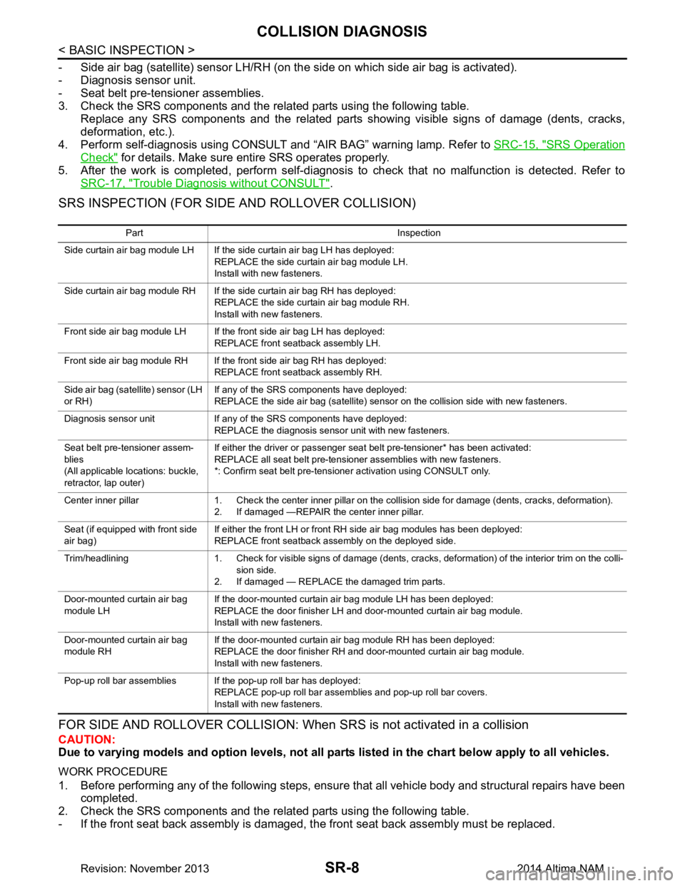
SRS INSPECTION (FOR SIDE AND ROLLOVER COLLISION)
FOR SIDE AND ROLLOVER COLLISION: When SRS is not activated in a collision
CAUTION:
Due to varying models and option levels, not all part s listed in the chart below apply to all vehicles.
WORK PROCEDURE
1. Before performing any of the following steps, ensur e that all vehicle body and structural repairs have been
completed.
2. Check the SRS components and the related parts using the following table.
- If the front seat back assembly is damaged, t he front seat back assembly must be replaced.
Part Inspection
Side curtain air bag module LH If the side curtain air bag LH has deployed: REPLACE the side curtain air bag module LH.
Install with new fasteners.
Side curtain air bag module RH If the side curtain air bag RH has deployed: REPLACE the side curtain air bag module RH.
Install with new fasteners.
Front side air bag module LH If the front side air bag LH has deployed: REPLACE front seatback assembly LH.
Front side air bag module RH If the front side air bag RH has deployed: REPLACE front seatback assembly RH.
Side air bag (satellite) sensor (LH
or RH) If any of the SRS components have deployed:
REPLACE the side air bag (satellite) sensor on the collision side with new fasteners.
Diagnosis sensor unit If any of the SRS components have deployed: REPLACE the diagnosis sensor unit with new fasteners.
Seat belt pre-tensioner assem-
blies
(All applicable locations: buckle,
retractor, lap outer) If either the driver or passenger seat belt pre-tensioner* has been activated:
REPLACE all seat belt pre-tensioner assemblies with new fasteners.
*: Confirm seat belt pre-tensioner activation using CONSULT only.
Center inner pillar 1. Check the center inner pillar on the collision side for damage (dents, cracks, deformation). 2. If damaged —REPAIR the center inner pillar.
Seat (if equipped with front side
air bag) If either the front LH or front RH side air bag modules has been deployed:
REPLACE front seatback assembly on the deployed side.
Trim/headlining 1. Check for visible signs of damage (dents, cracks, deformation) of the interior trim on the colli- sion side.
2. If damaged — REPLACE the damaged trim parts.
Door-mounted curtain air bag
module LH If the door-mounted curtain air bag module LH has been deployed:
REPLACE the door finisher LH and door-mounted curtain air bag module.
Install with new fasteners.
Door-mounted curtain air bag
module RH If the door-mounted curtain air bag module RH has been deployed:
REPLACE the door finisher RH and door-mounted curtain air bag module.
Install with new fasteners.
Pop-up roll bar assemblies If the pop-up roll bar has deployed: REPLACE pop-up roll bar assemblies and pop-up roll bar covers.
Install with new fasteners.
Revision: November 20132014 Altima NAM