2014 NISSAN TEANA Center
[x] Cancel search: CenterPage 4619 of 4801
![NISSAN TEANA 2014 Service Manual
TM-404
< REMOVAL AND INSTALLATION >[CVT: RE0F10E]
CVT OIL WARMER SYSTEM
• The illustrations indicate the view from the hose ends.
• When installing hose clamps, the center line of each clamp tab](/manual-img/5/57390/w960_57390-4618.png "NISSAN TEANA 2014 Service Manual
TM-404
< REMOVAL AND INSTALLATION >[CVT: RE0F10E]
CVT OIL WARMER SYSTEM
• The illustrations indicate the view from the hose ends.
• When installing hose clamps, the center line of each clamp tab")
TM-404
< REMOVAL AND INSTALLATION >[CVT: RE0F10E]
CVT OIL WARMER SYSTEM
• The illustrations indicate the view from the hose ends.
• When installing hose clamps, the center line of each clamp tab should be positioned as shown.
CVT FLUID COOLER HOSE : InspectionINFOID:0000000009464364
INSPECTION AFTER INSTALLATION
Check for CVT fluid leakage and check CVT fluid level. Refer to TM-377, "Inspection".
CVT OIL WARMER
CVT OIL WARMER : Exploded ViewINFOID:0000000009464365
CVT OIL WARMER : Removal and InstallationINFOID:0000000009464366
REMOVAL
WARNING:
Do not remove the radiator cap when the engine is hot. Serious burns could occur from high pressure
coolant escaping from the radiator. Wrap a thick clot h around the cap. Slowly turn it a quarter turn to
allow built-up pressure to escape. Carefully remove the cap by turning it all the way.
CAUTION:
Perform when the engine is cold.
1. Remove front under cover. Refer to EXT-28, "Removal and Installation"
.
2. Remove CVT water hose inlet and CVT water hose outlet from CVT oil warmer. Refer to TM-199,
"WATER HOSE : Exploded View".
3. Remove CVT fluid cooler hose inlet and CVT fluid cooler hose outlet from CVT oil warmer. Refer to TM-
201, "CVT FLUID COOLER HOSE : Exploded View".
(C): Front
ALDIA0366ZZ
Transaxle assembly CVT oil warmer
: N·m (kg-m, ft-lb)
JSDIA5031GB
Revision: November 20132014 Altima NAMRevision: November 20132014 Altima NAM
Page 4629 of 4801

VTL-1
VENTILATION, HEATER & AIR CONDITIONER
C
D E
F
G H
J
K L
M
SECTION VTL
A
B
VTL
N
O P
CONTENTS
VENTILATION SYSTEM
PRECAUTION ................ ...............................2
PRECAUTIONS .............................................. .....2
Precaution for Supplemental Restraint System
(SRS) "AIR BAG" and "SEAT BELT PRE-TEN-
SIONER" ............................................................. ......
2
Precaution for Work ..................................................2
PREPARATION ............................................3
PREPARATION .............................................. .....3
Special Service Tool ........................................... ......3
Commercial Service Tool ..........................................3
PERIODIC MAINTENANCE ..........................4
IN-CABIN MICROFILTER .............................. .....4
Removal and Installation ...........................................4
SYSTEM DESCRIPTION . .............................5
IN-CABIN MICROFILTER .............................. .....5
Description .......................................................... ......5
REMOVAL AND INSTALLATION ................6
DUCTS AND GRILLES .................................. .....6
Exploded View .................................................... ......6
DEFROSTER NOZZLE .......................................... ......7
DEFROSTER NOZZLE : Removal and Installation
......
7
CENTER VENTILATOR DUCT .............................. ......7
CENTER VENTILATOR DUCT : Removal and In-
stallation .............................................................. ......
7
SIDE DEFROSTER DUCT ..................................... ......7
SIDE DEFROSTER DUCT : Removal and Instal-
lation .................................................................... ......
7
FRONT FLOOR DUCT .......................................... ......8
FRONT FLOOR DUCT : Removal and Installation
- Front Floor Duct ................................................ .....
8
FRONT FLOOR DUCT : Removal and Installation
- Front Floor Connecting Duct ............................. .....
8
FRONT FLOOR DUCT : Removal and Installation
- Front Floor Duct Nozzle .................................... .....
8
ADAPTOR DUCT ................................................... .....8
ADAPTOR DUCT : Removal and Installation -
Adaptor Duct ........................................................ .....
8
ADAPTOR DUCT : Removal and Installation -
Adaptor Extension Duct ....................................... .....
9
REAR CENTER VENTILATOR DUCT ................... .....9
REAR CENTER VENTILATOR DUCT : Removal
and Installation .................................................... .....
9
Exploded View .........................................................10
CENTER VENTILATOR GRILLE ........................... ....10
CENTER VENTILATOR GRILLE : Removal and
Installation ........................................................... ....
11
SIDE VENTILATOR GRILLE ................................. ....11
SIDE VENTILATOR GRILLE : Removal and In-
stallation .............................................................. ....
11
SIDE DEFROSTER GRILLE .................................. ....11
SIDE DEFROSTER GRILLE : Removal and In-
stallation .............................................................. ....
11
REAR CENTER VENTILATOR GRILLE ............... ....12
REAR CENTER VENTILATOR GRILLE : Remov-
al and Installation ................................................. ....
12
BLOWER UNIT .................................................13
BLOWER UNIT ...................................................... ....13
BLOWER UNIT : Exploded View .............................13
BLOWER UNIT : Removal and Installation .............13
BLOWER MOTOR ................................................. ....13
BLOWER MOTOR : Removal and Installation ........13
Revision: November 20132014 Altima NAM
Page 4635 of 4801

DUCTS AND GRILLESVTL-7
< REMOVAL AND INSTALLATION >
C
D E
F
G H
J
K L
M A
B
VTL
N
O P
DEFROSTER NOZZLE
DEFROSTER NOZZLE : Removal and InstallationINFOID:0000000009461577
REMOVAL
1. Remove the side defroster ducts (LH/RH). Refer to VTL-7, "SIDE DEFROSTER DUCT : Removal and
Installation".
2. Remove the defroster nozzle screws (A).
3. Release the defroster nozzle pawls. : Pawl
4. Remove the defroster nozzle (1).
INSTALLATION
Installation is in the reverse order of removal.
CENTER VENTILATOR DUCT
CENTER VENTILATOR DUCT : Removal and InstallationINFOID:0000000009461578
REMOVAL
1. Remove the instrument panel assembly. Refer to IP-15, "Removal and Installation".
2. Remove the center ventilator duct screws (A).
3. Remove the center ventilator duct.
INSTALLATION
Installation is in the reverse order of removal.
SIDE DEFROSTER DUCT
SIDE DEFROSTER DUCT : Re moval and InstallationINFOID:0000000009461579
REMOVAL
1. Remove the center ventilator duct. Refer to VTL-7, "CENTER VENTILATOR DUCT : Removal and Instal-
lation".
1. Defroster nozzle 2. Side defroster duct (LH) 3. Center ventilator duct
4. Heating and cooling unit assembly 5. Front floor connecting duct (LH) 6. Front floor duct (LH)
7. Front floor duct nozzle (LH) 8. Rear center ventilator duct 9. Front floor duct nozzle (RH)
10. Front floor duct (RH) 11. Adaptor extension duct 12. Adaptor duct
13. Front floor connecting duct (RH) 14. Side defroster duct (RH) Front
ALIIA0613ZZ
ALIIA0614ZZ
Revision: November 20132014 Altima NAM
Page 4636 of 4801
VTL-8
< REMOVAL AND INSTALLATION >
DUCTS AND GRILLES
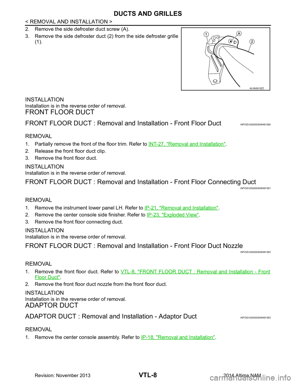
2. Remove the side defroster duct screw (A).
3. Remove the side defroster duct (2) from the side defroster grille
(1).
INSTALLATION
Installation is in the reverse order of removal.
FRONT FLOOR DUCT
FRONT FLOOR DUCT : Removal and In stallation - Front Floor DuctINFOID:0000000009461580
REMOVAL
1. Partially remove the front of the floor trim. Refer to INT-27, "Removal and Installation".
2. Release the front floor duct clip.
3. Remove the front floor duct.
INSTALLATION
Installation is in the reverse order of removal.
FRONT FLOOR DUCT : Removal and Installa tion - Front Floor Connecting Duct
INFOID:0000000009461581
REMOVAL
1. Remove the instrument lower panel LH. Refer to IP-21, "Removal and Installation".
2. Remove the center console side finisher. Refer to IP-23, "Exploded View"
.
3. Remove the front floor connecting duct.
INSTALLATION
Installation is in the reverse order of removal.
FRONT FLOOR DUCT : Removal and Insta llation - Front Floor Duct Nozzle
INFOID:0000000009461582
REMOVAL
1. Remove the front floor duct. Refer to VTL-8, "FRONT FLOOR DUCT : Removal and Installation - Front
Floor Duct".
2. Remove the front floor duct nozzle from the front floor duct.
INSTALLATION
Installation is in the reverse order of removal.
ADAPTOR DUCT
ADAPTOR DUCT : Removal and Installation - Adaptor DuctINFOID:0000000009461583
REMOVAL
1. Remove the center console assembly. Refer to IP-18, "Removal and Installation".
ALIIA0612ZZ
Revision: November 20132014 Altima NAM
Page 4637 of 4801
DUCTS AND GRILLESVTL-9
< REMOVAL AND INSTALLATION >
C
D E
F
G H
J
K L
M A
B
VTL
N
O P
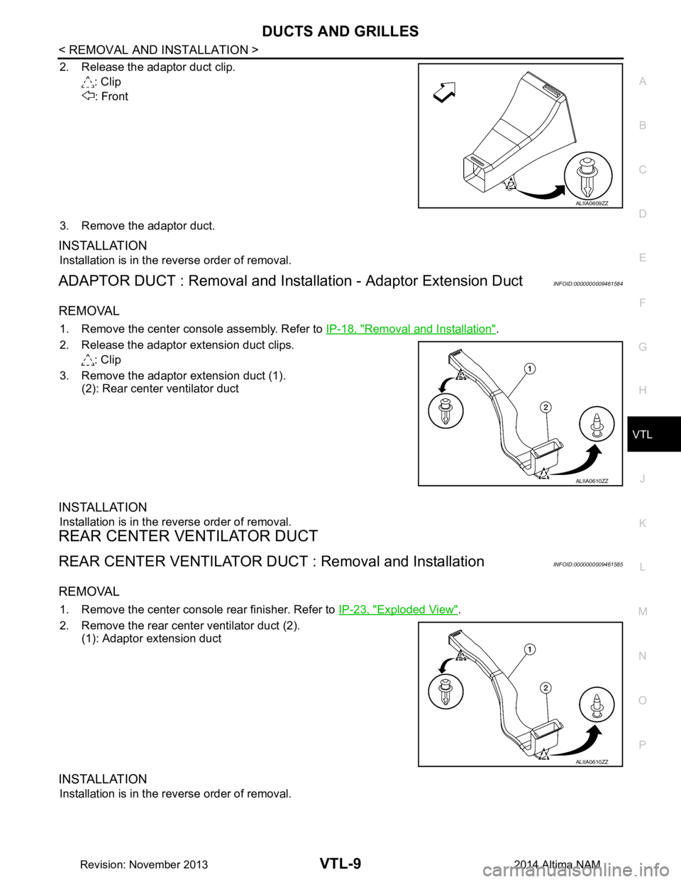
2. Release the adaptor duct clip. : Clip
: Front
3. Remove the adaptor duct.
INSTALLATION
Installation is in the reverse order of removal.
ADAPTOR DUCT : Removal and Insta llation - Adaptor Extension DuctINFOID:0000000009461584
REMOVAL
1. Remove the center console assembly. Refer to IP-18, "Removal and Installation".
2. Release the adaptor extension duct clips. : Clip
3. Remove the adaptor extension duct (1). (2): Rear center ventilator duct
INSTALLATION
Installation is in the reverse order of removal.
REAR CENTER VENTILATOR DUCT
REAR CENTER VENTILATOR DUCT : Removal and InstallationINFOID:0000000009461585
REMOVAL
1. Remove the center console rear finisher. Refer to IP-23, "Exploded View".
2. Remove the rear center ventilator duct (2). (1): Adaptor extension duct
INSTALLATION
Installation is in the reverse order of removal.
ALIIA0609ZZ
ALIIA0610ZZ
ALIIA0610ZZ
Revision: November 20132014 Altima NAM
Page 4638 of 4801
VTL-10
< REMOVAL AND INSTALLATION >
DUCTS AND GRILLES
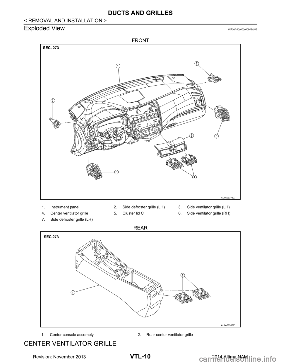
Exploded View
INFOID:0000000009461586
FRONT
REAR
CENTER VENTIL AT O R G R I L L E
ALIIA0637ZZ
1. Instrument panel 2. Side defroster grille (LH) 3. Side ventilator grille (LH)
4. Center ventilator grille 5. Cluster lid C 6. Side ventilator grille (RH)
7. Side defroster grille (LH)
ALIIA0638ZZ
1. Center console assembly 2. Rear center ventilator grille
Revision: November 20132014 Altima NAM
Page 4639 of 4801
DUCTS AND GRILLESVTL-11
< REMOVAL AND INSTALLATION >
C
D E
F
G H
J
K L
M A
B
VTL
N
O P
CENTER VENTILATOR GRILLE : Removal and InstallationINFOID:0000000009461587
REMOVAL
1. Remove cluster lid C. Refer to IP-20, "Cluster Lid C".
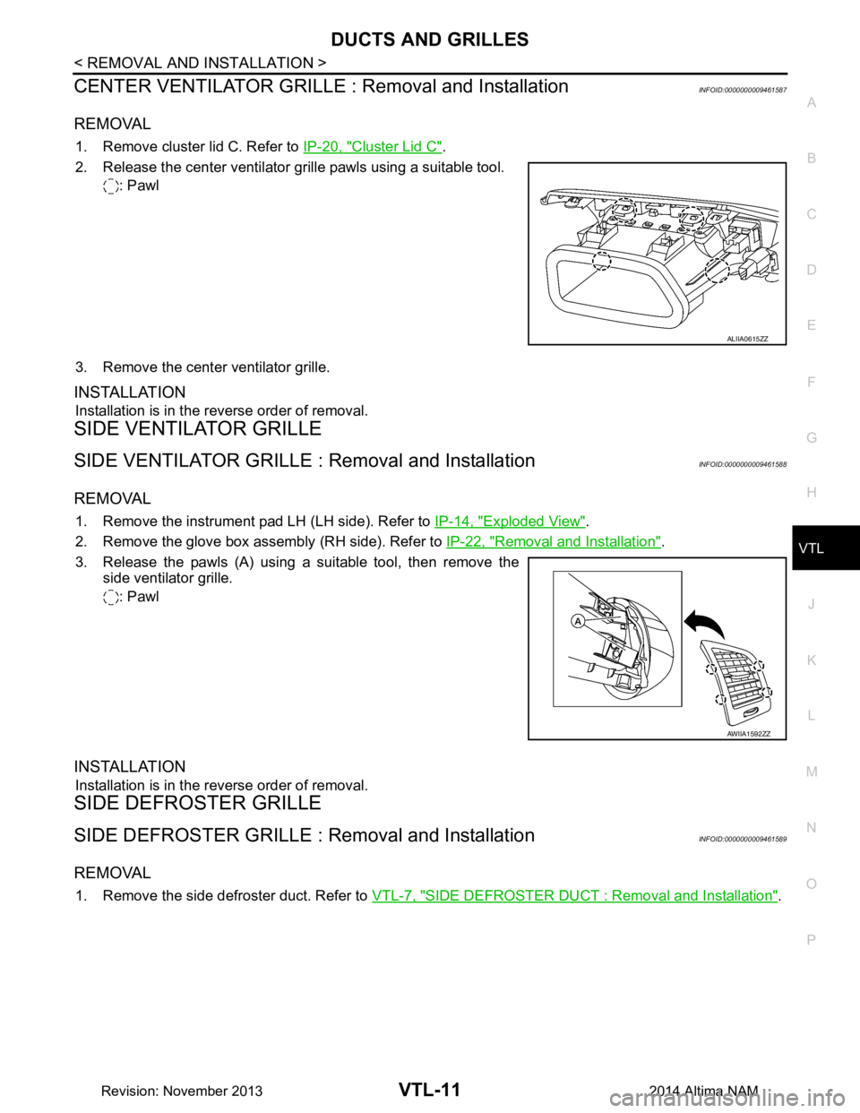
2. Release the center ventilator grille pawls using a suitable tool. : Pawl
3. Remove the center ventilator grille.
INSTALLATION
Installation is in the reverse order of removal.
SIDE VENTILATOR GRILLE
SIDE VENTILATOR GRILLE : Removal and InstallationINFOID:0000000009461588
REMOVAL
1. Remove the instrument pad LH (LH side). Refer to IP-14, "Exploded View".
2. Remove the glove box assembly (RH side). Refer to IP-22, "Removal and Installation"
.
3. Release the pawls (A) using a suitable tool, then remove the side ventilator grille.
: Pawl
INSTALLATION
Installation is in the reverse order of removal.
SIDE DEFROSTER GRILLE
SIDE DEFROSTER GRILLE : Removal and InstallationINFOID:0000000009461589
REMOVAL
1. Remove the side defroster duct. Refer to VTL-7, "SIDE DEFROSTER DUCT : Removal and Installation".
ALIIA0615ZZ
AWIIA1592ZZ
Revision: November 20132014 Altima NAM
Page 4640 of 4801
VTL-12
< REMOVAL AND INSTALLATION >
DUCTS AND GRILLES
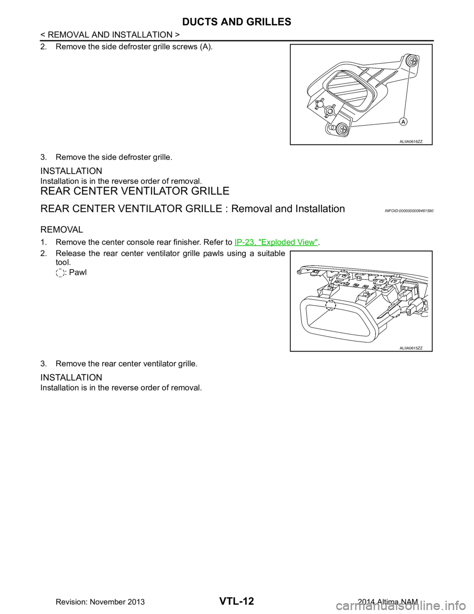
2. Remove the side defroster grille screws (A).
3. Remove the side defroster grille.
INSTALLATION
Installation is in the reverse order of removal.
REAR CENTER VENTILATOR GRILLE
REAR CENTER VENTILATOR GRI LLE : Removal and InstallationINFOID:0000000009461590
REMOVAL
1. Remove the center console rear finisher. Refer to IP-23, "Exploded View".
2. Release the rear center ventilator grille pawls using a suitable tool.
: Pawl
3. Remove the rear center ventilator grille.
INSTALLATION
Installation is in the reverse order of removal.
ALIIA0616ZZ
ALIIA0615ZZ
Revision: November 20132014 Altima NAM