2014 NISSAN TEANA Center
[x] Cancel search: CenterPage 3971 of 4801
COLLISION DIAGNOSISSR-9
< BASIC INSPECTION >
C
D E
F
G
I
J
K L
M A
B
SR
N
O P
- If the door finisher assembly is damaged, the door finisher assembly and door-mounted curtain air bag
module must be replaced.
3. Perform self-diagnosis using CONSULT and “AIR BAG” warning lamp. Refer to SRC-15, "SRS Operation
Check" for details. Make sure entire SRS operates properly.
4. After the work is completed, perform self-diagnosis to check that no malfunction is detected. Refer to
SRC-17, "Trouble Diagnosis without CONSULT"
.
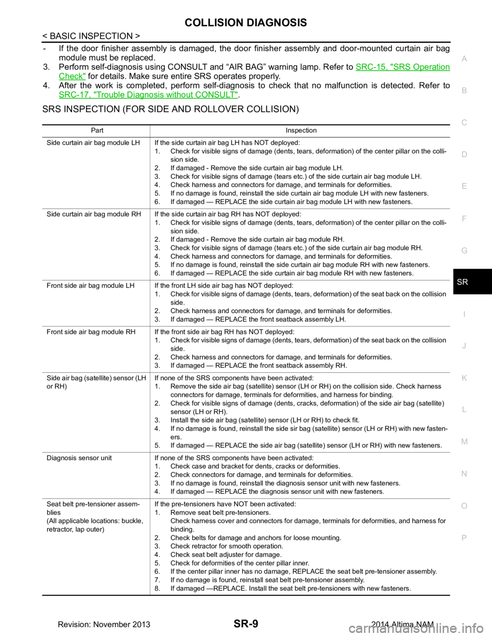
SRS INSPECTION (FOR SIDE AND ROLLOVER COLLISION)
Part Inspection
Side curtain air bag module LH If the side curtain air bag LH has NOT deployed: 1. Check for visible signs of damage (dents, tears, deformation) of the center pillar on the colli-sion side.
2. If damaged - Remove the side curtain air bag module LH.
3. Check for visible signs of damage (tears etc.) of the side curtain air bag module LH.
4. Check harness and connectors for damage, and terminals for deformities.
5. If no damage is found, reinstall the side curtain air bag module LH with new fasteners.
6. If damaged — REPLACE the side curtain air bag module LH with new fasteners.
Side curtain air bag module RH If the side curtain air bag RH has NOT deployed: 1. Check for visible signs of damage (dents, tears, deformation) of the center pillar on the colli-
sion side.
2. If damaged - Remove the side curtain air bag module RH.
3. Check for visible signs of damage (tears etc.) of the side curtain air bag module RH.
4. Check harness and connectors for damage, and terminals for deformities.
5. If no damage is found, reinstall the side curtain air bag module RH with new fasteners.
6. If damaged — REPLACE the side curtain air bag module RH with new fasteners.
Front side air bag module LH If the front LH side air bag has NOT deployed: 1. Check for visible signs of damage (dents, tears, deformation) of the seat back on the collision side.
2. Check harness and connectors for damage, and terminals for deformities.
3. If damaged — REPLACE the front seatback assembly LH.
Front side air bag module RH If the front side air bag RH has NOT deployed: 1. Check for visible signs of damage (dents, tears, deformation) of the seat back on the collision side.
2. Check harness and connectors for damage, and terminals for deformities.
3. If damaged — REPLACE the front seatback assembly RH.
Side air bag (satellite) sensor (LH
or RH) If none of the SRS components have been activated:
1. Remove the side air bag (satellite) sensor (LH or RH) on the collision side. Check harness
connectors for damage, terminals for deformities, and harness for binding.
2. Check for visible signs of damage (dents, cracks, deformation) of the side air bag (satellite) sensor (LH or RH).
3. Install the side air bag (satellite) sensor (LH or RH) to check fit.
4. If no damage is found, reinstall the side sir bag (satellite) sensor (LH or RH) with new fasten- ers.
5. If damaged — REPLACE the side air bag (satellite) sensor (LH or RH) with new fasteners.
Diagnosis sensor unit If none of the SRS components have been activated: 1. Check case and bracket for dents, cracks or deformities.
2. Check connectors for damage, and terminals for deformities.
3. If no damage is found, reinstall the diagnosis sensor unit with new fasteners.
4. If damaged — REPLACE the diagnosis sensor unit with new fasteners.
Seat belt pre-tensioner assem-
blies
(All applicable locations: buckle,
retractor, lap outer) If the pre-tensioners have NOT been activated:
1. Remove seat belt pre-tensioners. Check harness cover and connectors for damage, terminals for deformities, and harness for
binding.
2. Check belts for damage and anchors for loose mounting.
3. Check retractor for smooth operation.
4. Check seat belt adjuster for damage.
5. Check for deformities of the center pillar inner.
6. If the center pillar inner has no damage, REPLACE the seat belt pre-tensioner assembly.
7. If no damage is found, reinstall seat belt pre-tensioner assembly.
8. If damaged —REPLACE. Install the seat belt pre-tensioners with new fasteners.
Revision: November 20132014 Altima NAM
Page 3972 of 4801
SR-10
< BASIC INSPECTION >
COLLISION DIAGNOSIS
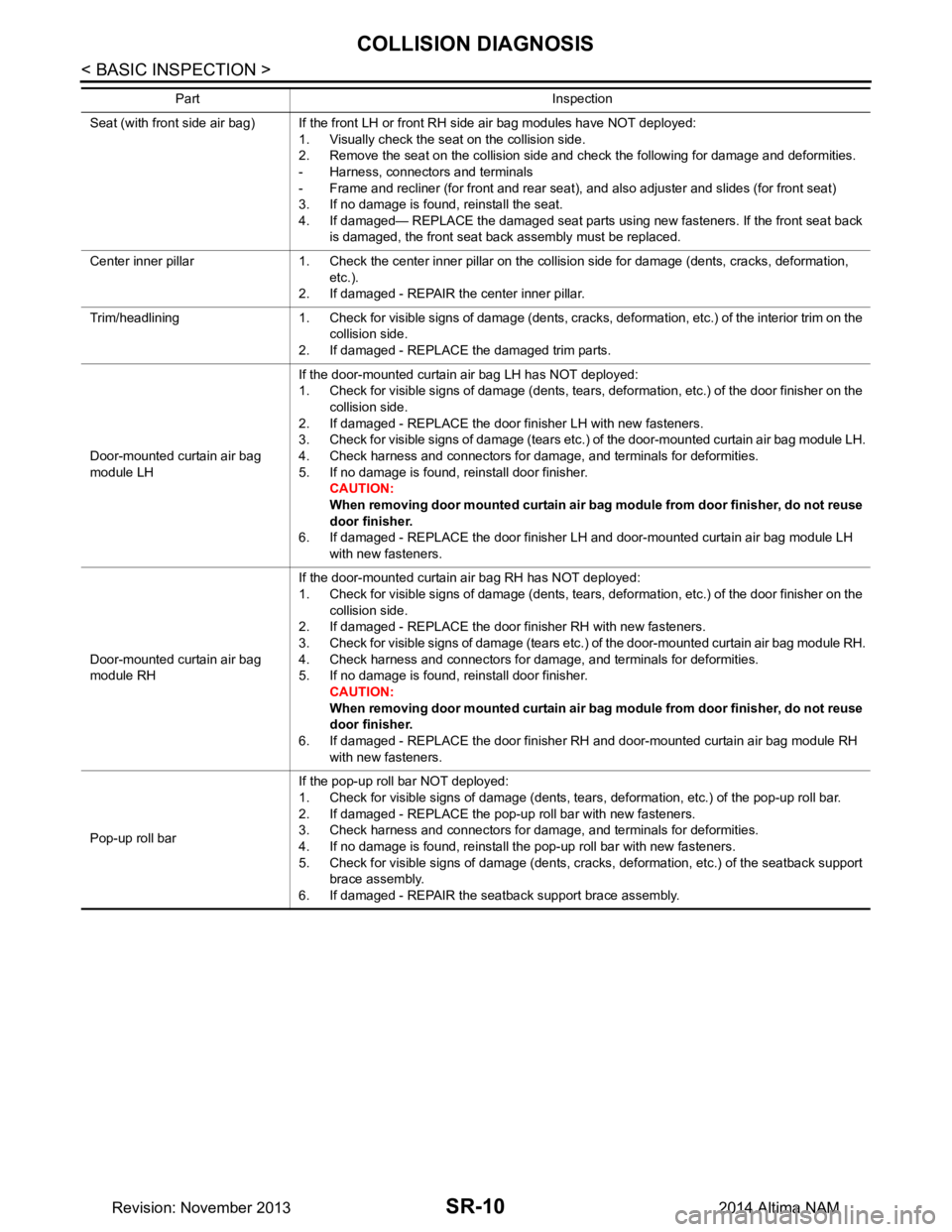
Seat (with front side air bag) If the front LH or front RH side air bag modules have NOT deployed: 1. Visually check the seat on the collision side.
2. Remove the seat on the collision side and check the following for damage and deformities.
- Harness, connectors and terminals
- Frame and recliner (for front and rear seat), and also adjuster and slides (for front seat)
3. If no damage is found, reinstall the seat.
4. If damaged— REPLACE the damaged seat parts using new fasteners. If the front seat back is damaged, the front seat back assembly must be replaced.
Center inner pillar 1. Check the center inner pillar on the collision side for damage (dents, cracks, deformation, etc.).
2. If damaged - REPAIR the center inner pillar.
Trim/headlining 1. Check for visible signs of damage (dents, cracks, deformation, etc.) of the interior trim on the collision side.
2. If damaged - REPLACE the damaged trim parts.
Door-mounted curtain air bag
module LH If the door-mounted curtain air bag LH has NOT deployed:
1. Check for visible signs of damage (dents, tears, deformation, etc.) of the door finisher on the collision side.
2. If damaged - REPLACE the door finisher LH with new fasteners.
3. Check for visible signs of damage (tears etc.) of the door-mounted curtain air bag module LH.
4. Check harness and connectors for damage, and terminals for deformities.
5. If no damage is found, reinstall door finisher. CAUTION:
When removing door mounted curtain air bag module from door finisher, do not reuse
door finisher.
6. If damaged - REPLACE the door finisher LH and door-mounted curtain air bag module LH with new fasteners.
Door-mounted curtain air bag
module RH If the door-mounted curtain air bag RH has NOT deployed:
1. Check for visible signs of damage (dents, tears, deformation, etc.) of the door finisher on the collision side.
2. If damaged - REPLACE the door finisher RH with new fasteners.
3. Check for visible signs of damage (tears etc.) of the door-mounted curtain air bag module RH.
4. Check harness and connectors for damage, and terminals for deformities.
5. If no damage is found, reinstall door finisher.
CAUTION:
When removing door mounted curtain air bag module from door finisher, do not reuse
door finisher.
6. If damaged - REPLACE the door finisher RH and door-mounted curtain air bag module RH with new fasteners.
Pop-up roll bar If the pop-up roll bar NOT deployed:
1. Check for visible signs of damage (dents, tears, deformation, etc.) of the pop-up roll bar.
2. If damaged - REPLACE the pop-up roll bar with new fasteners.
3. Check harness and connectors for damage, and terminals for deformities.
4. If no damage is found, reinstall the pop-up roll bar with new fasteners.
5. Check for visible signs of damage (dents, cracks, deformation, etc.) of the seatback support
brace assembly.
6. If damaged - REPAIR the seatback support brace assembly.
Part Inspection
Revision: November 20132014 Altima NAM
Page 3988 of 4801
SR-26
< REMOVAL AND INSTALLATION >
DIAGNOSIS SENSOR UNIT
DIAGNOSIS SENSOR UNIT
Removal and InstallationINFOID:0000000009463080
REMOVAL
WARNING:
• Before servicing the SRS, turn ig nition switch OFF, disconnect both battery terminals and wait at
least three minutes.
• Before disconnecting the air bag diagnosis sensor unit harness conn ectors, be sure to disconnect
each harness connector of the front shoulder belt pre-tensioners to prevent accidental air bag
deployment by static electricity and seat belt pre-tensioner operation.
• Do not use the air tools or electric tools for servicing.
• When replacing the air bag diagno sis sensor unit, always check with th e parts department for the lat-
est parts information. Installing an incorrect air bag diagnosis sen sor unit may or may not cause the
air bag warning lamp to illuminate and may cause in correct deployment of the supplemental air bags
and seat belt pre-tensioners in a collision r esulting in serious personal injury or death.
1. Always check the air bag diagnosis sensor unit ECU discriminated number (identification number) or part
number using CONSULT.
2. Disconnect both the negative and positive battery terminal s, then wait at least three minutes. Refer to PG-
73, "Removal and Installation (Battery)".
3. Disconnect the harness connector fo r the following SRS components: SB-8, "Removal and Installation"
(Front shoulder belt pre-tensioner LH/RH).
4. Remove the center console. Refer to IP-18, "Removal and Installation"
.
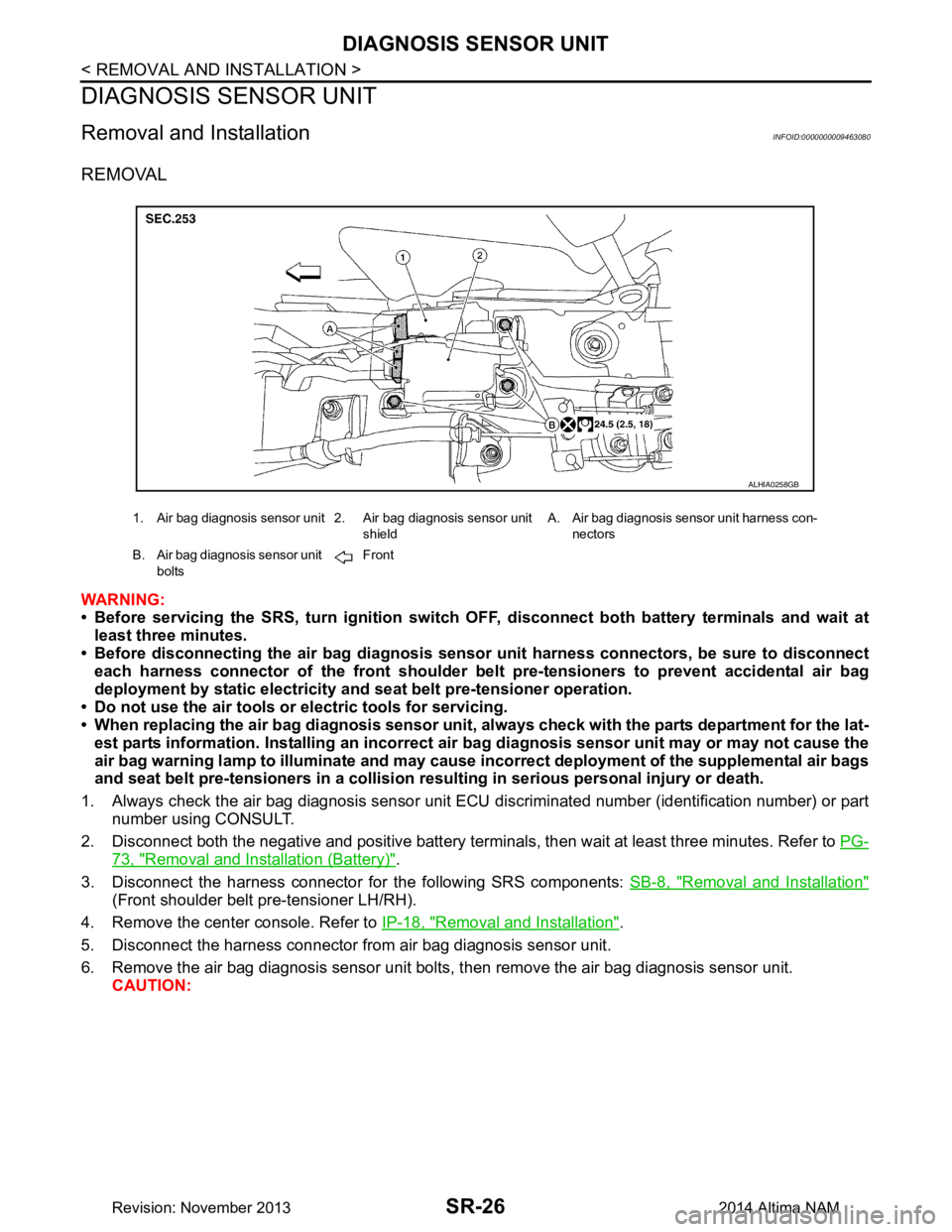
5. Disconnect the harness connector from air bag diagnosis sensor unit.
6. Remove the air bag diagnosis sensor unit bolts , then remove the air bag diagnosis sensor unit.
CAUTION:
1. Air bag diagnosis sensor unit 2. Air bag diagnosis sensor unit
shieldA. Air bag diagnosis sensor unit harness con-
nectors
B. Air bag diagnosis sensor unit bolts Front
ALHIA0258GB
Revision: November 20132014 Altima NAM
Page 3993 of 4801

PASSENGER AIR BAG INDICATORSR-31
< REMOVAL AND INSTALLATION >
C
D E
F
G
I
J
K L
M A
B
SR
N
O P
PASSENGER AIR BAG INDICATOR
Removal and InstallationINFOID:0000000009463084
The passenger air bag indicator is part of the center ventilator grill assembly. For removal and installation of
the center ventilator grill assembly. Refer to IP-15, "Removal and Installation"
.
Revision: November 20132014 Altima NAM
Page 3999 of 4801
SRC-6
< SYSTEM DESCRIPTION >
COMPONENT PARTS
Component Description
INFOID:0000000009460705
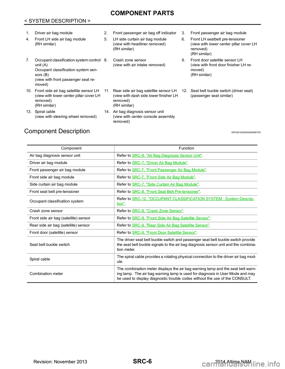
1. Driver air bag module 2. Front passenger air bag off indicator 3. Front passenger air bag module
4. Front LH side air bag module (RH similar) 5. LH side curtain air bag module
(view with headliner removed)
(RH similar) 6. Front LH seatbelt pre-tensioner
(view with lower cent er pillar cover LH
removed)
(RH similar)
7. Occupant classification system control unit (A)
Occupant classification system sen-
sors (B)
(view with front passenger seat re-
moved) 8. Crash zone sensor
(view with air intake removed) 9. Front door satellite sensor LH
(view with front door finisher LH re-
moved)
(RH similar)
10. Front side air bag satellite sensor LH (view with lower cent er pillar cover LH
removed)
(RH similar) 11. Rear side air bag satellite sensor LH
(view with dash side lower finisher LH
removed)
(RH similar) 12. Seat belt buckle switch (driver seat)
(passenger seat similar)
13. Spiral cable (view with steeri ng wheel removed) 14. Air bag diagnosis sensor unit
(view with center console assembly
removed)
Component Function
Air bag diagnosis sensor unit Refer to SRC-8, "Air Bag Diagnosis Sensor Unit"
.
Driver air bag module Refer to SRC-7, "Driver Air Bag Module"
.
Front passenger air bag module Refer to SRC-7, "Front Passenger Air Bag Module"
.
Front side air bag module Refer to SRC-7, "Front Side Air Bag Module"
.
Side curtain air bag module Refer to SRC-7, "Side Curtain Air Bag Module"
.
Front seat belt pre-tensioner Refer to SRC-8, "Front Seat Belt Pre-tensioner"
.
Occupant classification system Refer to
SRC-12, "OCCUPANT CLASSIFICATION SYSTEM : System Descrip-
tion".
Crash zone sensor Refer to SRC-8, "Crash Zone Sensor"
.
Front side air bag (satellite) sensor Refer to SRC-8, "Front Side Air Bag Satellite Sensor"
.
Rear side air bag (satellite) sensor Refer to SRC-9, "Rear Side Air Bag Satellite Sensor"
.
Front door (satellite) sensor Refer to SRC-9, "Front Door Satellite Sensor"
.
Seat belt buckle switch The driver seat belt buckle switch and passenger seat belt buckle switch provide
the seat belt buckle signals to the air bag diagnosis sensor unit and the combina-
tion meter.
Sp iral c ab le The spiral cable provides a rotating physical connection to the driver air bag mod-
ule.
Combination meter The combination meter displays the air bag warning lamp and the seat belt warn-
ing lamp. The air bag warning lamp is used for diagnosis in User Mode and may
be used to display diagnostic trouble codes without the use of the CONSULT.
Revision: November 20132014 Altima NAMRevision: November 20132014 Altima NAM
Page 4001 of 4801
SRC-8
< SYSTEM DESCRIPTION >
COMPONENT PARTS
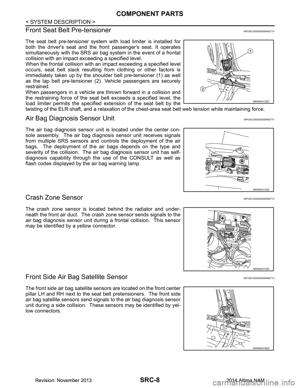
Front Seat Belt Pre-tensioner
INFOID:0000000009460710
The seat belt pre-tensioner system wi th load limiter is installed for
both the driver's seat and the front passenger's seat. It operates
simultaneously with the SRS air bag system in the event of a frontal
collision with an impact exceeding a specified level.
When the frontal collision with an im pact exceeding a specified level
occurs, seat belt slack resulting from clothing or other factors is
immediately taken up by the shoulder belt pre-tensioner (1) as well
as the lap belt pre-tensioner (2). Vehicle passengers are securely
restrained.
When passengers in a vehicle are thrown forward in a collision and
the restraining force of the seat belt exceeds a specified level, the
load limiter permits the specified extension of the seat belt by the
twisting of the ELR shaft, and a relaxation of the ches t-area seat belt web tension while maintaining force.
Air Bag Diagnosis Sensor UnitINFOID:0000000009460711
The air bag diagnosis sensor unit is located under the center con-
sole assembly. The air bag diagnosis sensor unit receives signals
from multiple SRS sensors and cont rols the deployment of the air
bags. The deployment of the air bags depends on the type and
severity of the collision. The air bag diagnosis sensor unit has self-
diagnosis capability through the use of the CONSULT as well as
flash codes displayed by the air bag warning lamp.
Crash Zone SensorINFOID:0000000009460712
The crash zone sensor is located behind the radiator and under-
neath the front air duct. The crash zone sensor sends signals to the
air bag diagnosis sensor unit during a frontal collision. This sensor
may be identified by a yellow connector.
Front Side Air B ag Satellite SensorINFOID:0000000009460713
The front side air bag satellite sensors are located on the front center
pillar LH and RH next to the seat belt pretensioners. The front side
air bag satellite sensors send signals to the air bag diagnosis sensor
unit during a side collision. Thes e sensors may be identified by yel-
low connectors.
AWHIA0413ZZ
AWHIA0414ZZ
AWHIA0415ZZ
AWHIA0416ZZ
Revision: November 20132014 Altima NAMRevision: November 20132014 Altima NAM
Page 4171 of 4801

STC-20
< BASIC INSPECTION >
DIAGNOSIS AND REPAIR WORK FLOW
YES >> GO TO 6.
NO >> Check harness and connectors based on the information obtained by interview.
6.REPAIR OR REPLACE THE MALFUNCTIONING COMPONENTS.
• Repair or replace the malfunctioning components.
• Reconnect part or connector after repairing or replacing.
• When DTC is detected, erase self-diagnostic results for “EPS”.
>> GO TO 8.
7.IDENTIFY THE MALFUNCTIONING SYSTEM BY SYMPTOM DIAGNOSIS
Estimate the malfunctioning system based on symptom diagnosis and perform inspection.
Can the malfunctioning system be identified?
YES >> GO TO 8.
NO >> Check harness and connectors based on the information obtained by interview.
8.FINAL CHECK
With CONSULT
1. Check the reference value for power steering control module.
2. Recheck the symptom and check that sympto m is not reproduced on the same conditions.
Is the symptom reproduced?
YES >> GO TO 3.
NO >> Inspection End.
Diagnostic Work SheetINFOID:0000000009460355
Description
• In general, customers have their own criteria for a pr oblem. Therefore, it is important to understand the
symptom and status well enough by asking the customer about his/her concerns carefully. To systemize all
the information for the diagnosis, prepare the interview sheet referring to the interview points.
• In some cases, multiple conditions that appear simultaneously may cause a DTC to be detected.
Interview sheet sample
Interview sheet
Customer
name MR/MSRegistration
number Initial year
registration
Vehicle type VIN
Storage date Engine Mileage km (Mile)
Symptom †
The steering wheel position (center) is in the wrong position.
† Warning lamp turns on.
† Noise †Vibration
† Others
( )
First occurrence †Recently †Others ( )
Frequency of occurrence †Always †Under a certain conditions of †Sometimes (time(s)/day)
Climate con-
ditions †
Irrelevant
Weather †Fine †Cloud †Rain †Snow †Others ( )
Temperature †Hot †Warm †Cool †Cold †Temperature [Approx. °C ( °F)]
Relative humidity †High †Moderate †Low
Road conditions †
Urban area †Suburb area †High way
† Mountain road (uphill or down hill) †Rough road
Revision: November 20132014 Altima NAMRevision: November 20132014 Altima NAM
Page 4242 of 4801
![NISSAN TEANA 2014 Service Manual
STRUCTURE AND OPERATIONTM-27
< SYSTEM DESCRIPTION > [CVT: RE0F10D]
C
EF
G H
I
J
K L
M A
B
TM
N
O P
TRANSAXLE : Component DescriptionINFOID:0000000009463984
FLUID COOLER & FLUID WARMER SYSTEM
Part na](/manual-img/5/57390/w960_57390-4241.png "NISSAN TEANA 2014 Service Manual
STRUCTURE AND OPERATIONTM-27
< SYSTEM DESCRIPTION > [CVT: RE0F10D]
C
EF
G H
I
J
K L
M A
B
TM
N
O P
TRANSAXLE : Component DescriptionINFOID:0000000009463984
FLUID COOLER & FLUID WARMER SYSTEM
Part na")
STRUCTURE AND OPERATIONTM-27
< SYSTEM DESCRIPTION > [CVT: RE0F10D]
C
EF
G H
I
J
K L
M A
B
TM
N
O P
TRANSAXLE : Component DescriptionINFOID:0000000009463984
FLUID COOLER & FLUID WARMER SYSTEM
Part name Function
Torque converter Increases engine torque and transmits it to the transaxle.
Oil pump Utilizes a vane-type oil pump that is driven by the engine through the oil pump drive chain in order to
increase efficiency of pump discharge volume in low-speed zone and optimize pump discharge volume
in high-speed zone. Discharged oil from oil pump is tr ansmitted to control valve. It is used as the oil of
primary and secondary pulley operation, the oil of clutch operation, and the lubricant for each part.
Forward clutch The forward clutch is wet and multiple plate type clutch that consists of clutch drum, piston, drive plate,
and driven plate. It is a clutch to move the vehicle forward by activating piston hydraulically, engaging
plates, and directly connecting sun gear and input shaft.
Reverse brake The reverse brake is a wet multiple-plate type brake that consists of transaxle case, piston, drive plate,
and driven plate. It is a brake to move the vehicle in reverse by activating piston hydraulically, engaging
plates, and fixing planetary gear.
Internal gear The internal gear is directly connected to forward clutch drum. It is a gear that moves the outer edge of
pinion planet of planet carrier. It transmits power to move the vehicle in reverse when the planet carrier
is fixed.
Planet carrier Composed of a carrier, pinion planet, and pinion shaft. This gear fixes and releases the planet carrier in
order to switch between forward and reverse driving.
Sun gear Sun gear is a set part with planet carrier and internal gear. It transmits transmitted force to primary fixed
sheave. It rotates in forward or reverse direction according to activation of either forward clutch or re-
verse brake.
Input shaft The input shaft is directly connected to forward clutch drum and transmits traction force from torque con-
verter. In shaft center, there are holes for hydraulic distribution to primary pulley and hydraulic distribution
for lockup ON/OFF.
Primary pulley It is composed of a pair of pulleys (the groove width is changed freely in the axial direction) and the steel belt. The groove width changes according to wrapping radius of steel belt and pulley from low status to
overdrive status continuously with non-step. It is controlled with the oil pressures of primary pulley and
secondary pulley.
Secondary pulley
Steel belt
Manual shaft When the manual shaft is in the P position, the parking rod that is linked to the manual shaft rotates the
parking pole. When the parking pole rotates, it engages with the parking gear, fixing the parking gear. As
a result, the secondary pulley that is integrated with the parking gear is fixed.
Parking rod
Parking pawl
Parking gear
Output gear
The deceleration gears are composed of 2 stages: primary deceleration (output gear, idler gear pair) and
secondary deceleration (reduction gear, final gear pair). All of these gears are helical gears.
Idler gear
Reduction gear
Differential
Torque converter regulator
valve Adjusts the feed pressure to the torque converter to the optimum pressure corresponding to the driving
condition.
Pressure regulator valve Adjusts the discharge pressure from the oil pump to the optimum pressure (line pressure) corresponding
to the driving condition.
Torque converter clutch
control valve Adjusts the torque converter engage and disengage pressures.
Manual valve Distributes the clutch operation pressure to each circuit according to the selector lever position.
Secondary reducing valve Reduces line pressure and adjusts secondary pressure.
Primary reducing valve Reduces line pressure and adjusts primary pressure.
Pilot valve A Reduces line pressure and adjusts pilot pressure to the solenoid valves listed below.
• Primary pressure solenoid valve
• Secondary pressure solenoid valve
• Select solenoid valve
• Line pressure solenoid valve
Pilot valve B Reduces pilot pressure and adjusts pilot pressure to the torque converter clutch solenoid valve.
Revision: November 20132014 Altima NAMRevision: November 20132014 Altima NAM