ROAD WHEELWT-53
< PERIODIC MAINTENANCE >
C
D
F
G H
I
J
K L
M A
B
WT
N
O P
PERIODIC MAINTENANCE
ROAD WHEEL
InspectionINFOID:0000000009464520
ALUMINUM WHEEL
1. Check tires for wear and improper inflation.
2. Check wheels for deformation, cracks and other damage. If deformed, remove wheel and check wheel
runout.
3. Remove tire from aluminum wheel and mount wheel on a tire balance machine.
CAUTION:
DO NOT use center hole cone-type clamping machines to
hold the wheel assembly during tire removal/installation or
balancing. Damage to the wheel finish, cladding or chrome
may occur. Use only rim-type or universal lug-type clamp-
ing machines to hold the wheel assembly.
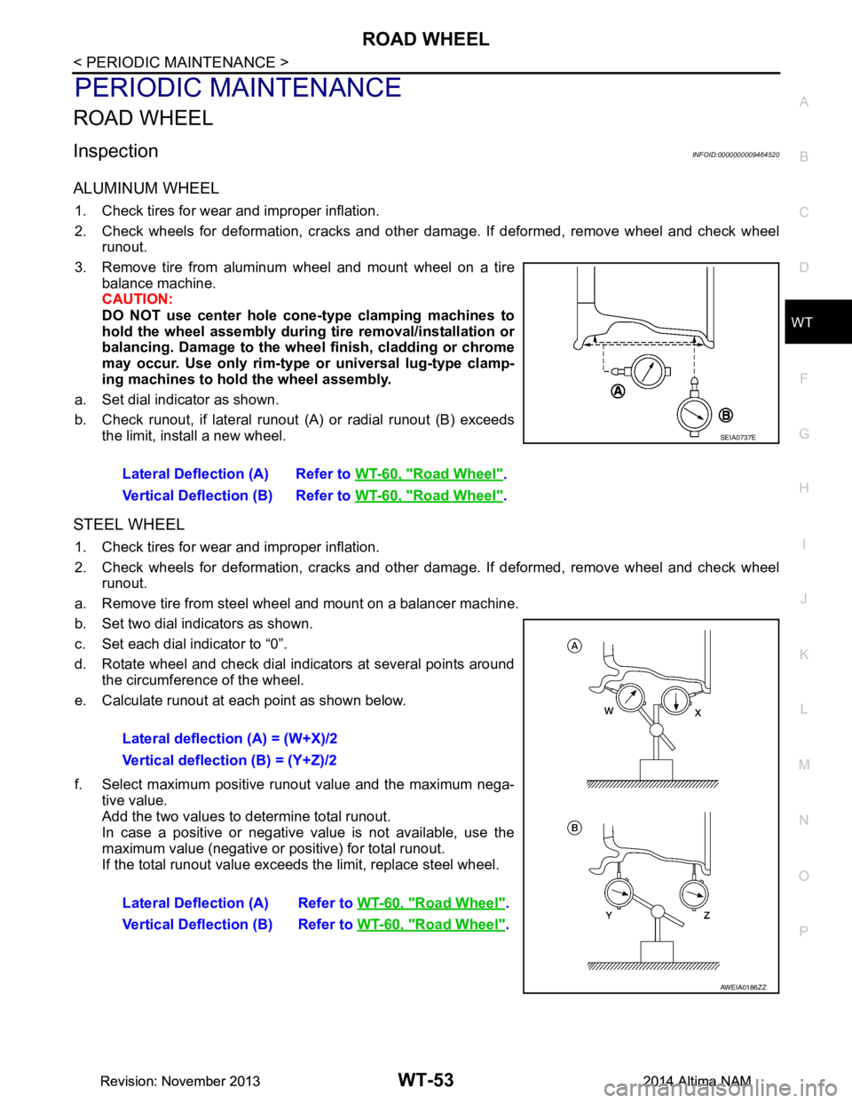
a. Set dial indicator as shown.
b. Check runout, if lateral runout (A) or radial runout (B) exceeds
the limit, install a new wheel.
STEEL WHEEL
1. Check tires for wear and improper inflation.
2. Check wheels for deformation, cracks and other damage. If deformed, remove wheel and check wheel
runout.
a. Remove tire from steel wheel and mount on a balancer machine.
b. Set two dial indicators as shown.
c. Set each dial indicator to “0”.
d. Rotate wheel and check dial indicators at several points around the circumference of the wheel.
e. Calculate runout at each point as shown below.
f. Select maximum positive runout value and the maximum nega- tive value.
Add the two values to determine total runout.
In case a positive or negative value is not available, use the
maximum value (negative or positive) for total runout.
If the total runout value exceeds the limit, replace steel wheel.
Lateral Deflection (A) Refer to
WT-60, "Road Wheel"
.
Vertical Deflection (B) Refer to WT-60, "Road Wheel"
.
SEIA0737E
Lateral deflection (A) = (W+X)/2
Vertical deflection (B) = (Y+Z)/2
Lateral Deflection (A) Refer to WT-60, "Road Wheel"
.
Vertical Deflection (B) Refer to WT-60, "Road Wheel"
.
AWEIA0186ZZ
Revision: November 20132014 Altima NAMRevision: November 20132014 Altima NAM
WASHER NOZZLE & TUBEWW-57
< REMOVAL AND INSTALLATION >
C
D E
F
G H
I
J
K
M A
B
WW
N
O P
3. Remove the hood insulator. Refer to DLK-170, "HOOD ASSEMBLY : Exploded View".
4. Disconnect the washer tube from the washer nozzles (LH/RH).
5. Remove the front under cover. Refer to EXT-28, "Removal and Installation"
.
6. Remove the fender protector (RH). Refer to EXT-26, "FENDER PROTECTOR : Removal and Installation"
.
7. Disconnect the washer tube from the washer pump.
8. Remove the washer tube.
Installation
Installation is in the reverse order of removal.
NOTE:
Fill washer tank with specified amount of fluid. Refer to WW-66, "Specifications"
.
REAR WASHER TUBE (IF EQUIPPED)
Removal
1. Drain the washer fluid.
2. Remove trunk lid finisher. Refer to INT-33, "TRUNK LID FINISHER : Removal and Installation"
.
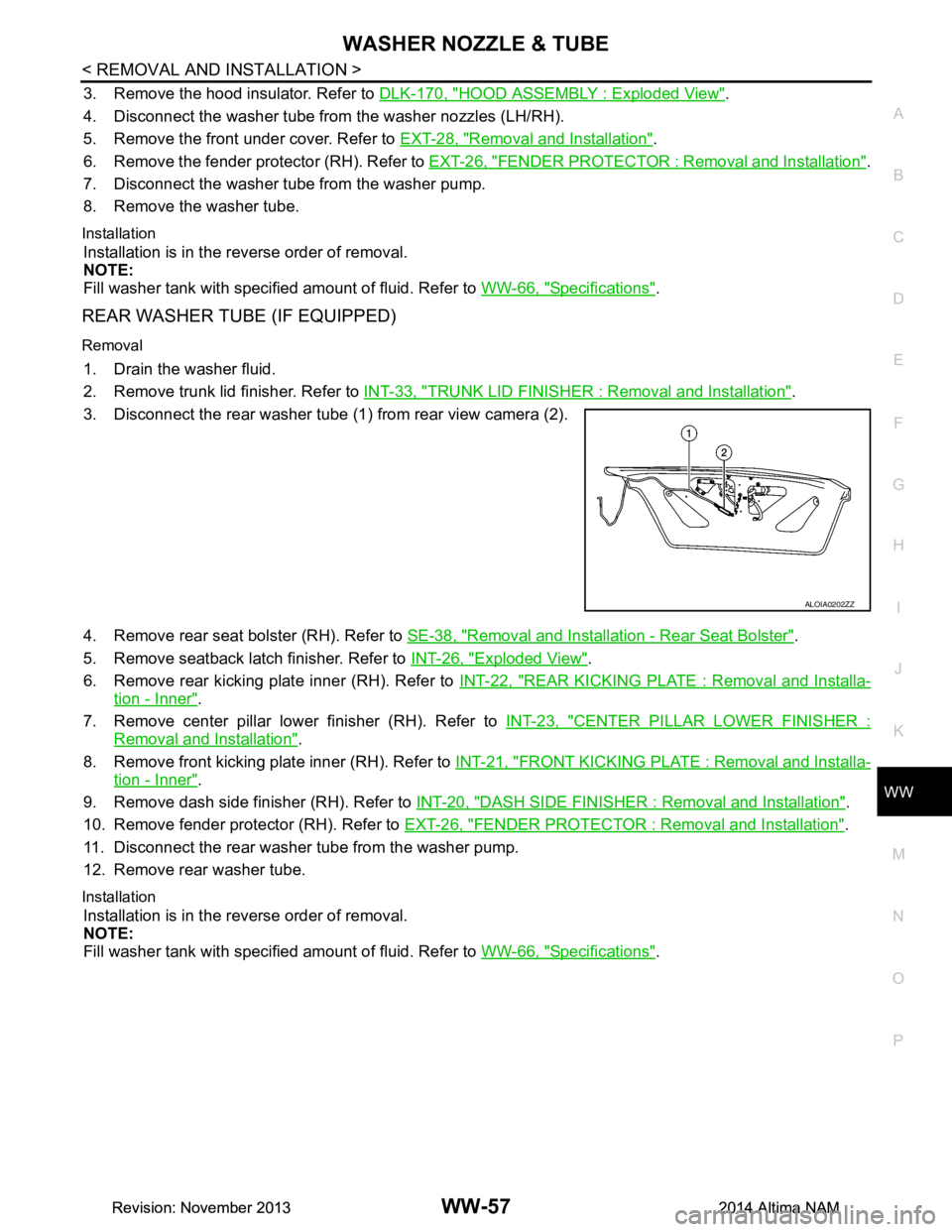
3. Disconnect the rear washer tube (1 ) from rear view camera (2).
4. Remove rear seat bolster (RH). Refer to SE-38, "Removal and Installation - Rear Seat Bolster"
.
5. Remove seatback latch finisher. Refer to INT-26, "Exploded View"
.
6. Remove rear kicking plate inner (RH). Refer to INT-22, "REAR KICKING PLATE : Removal and Installa-
tion - Inner".
7. Remove center pillar lower finisher (RH). Refer to INT-23, "CENTER PILLAR LOWER FINISHER :
Removal and Installation".
8. Remove front kicking plate inner (RH). Refer to INT-21, "FRONT KICKING PLATE : Removal and Installa-
tion - Inner".
9. Remove dash side finisher (RH). Refer to INT-20, "DASH SIDE FINISHER : Removal and Installation"
.
10. Remove fender protector (RH). Refer to EXT-26, "FENDER PROTECTOR : Removal and Installation"
.
11. Disconnect the rear washer tube from the washer pump.
12. Remove rear washer tube.
Installation
Installation is in the reverse order of removal.
NOTE:
Fill washer tank with specified amount of fluid. Refer to WW-66, "Specifications"
.
ALOIA0202ZZ
Revision: November 20132014 Altima NAMRevision: November 20132014 Altima NAM