2014 NISSAN TEANA torque
[x] Cancel search: torquePage 2533 of 4801
HOW TO USE THIS MANUALGI-5
< HOW TO USE THIS MANUAL >
C
D E
F
G H
I
J
K L
M B
GI
N
O P
SYMBOLS
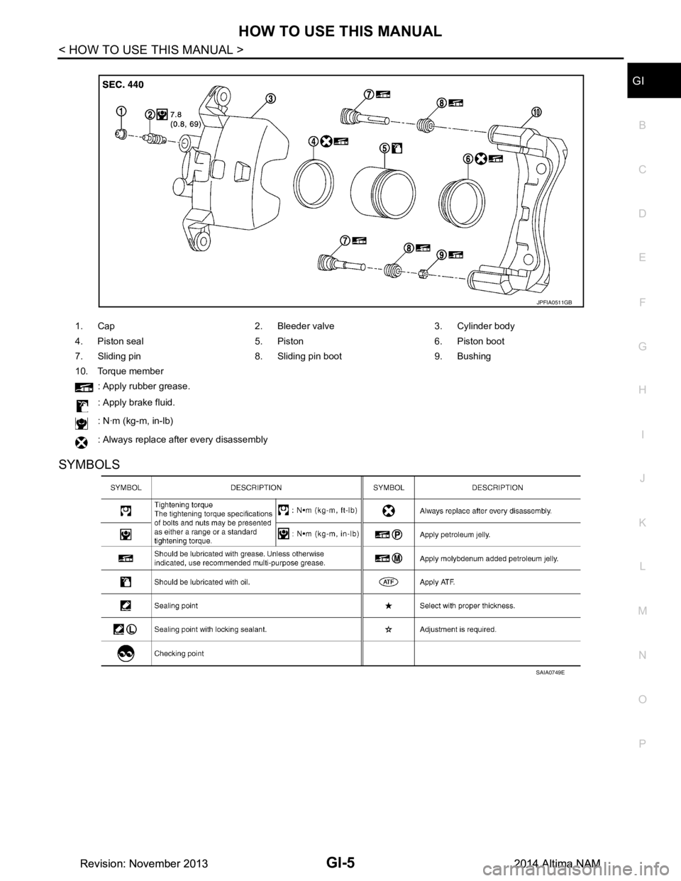
1. Cap 2. Bleeder valve 3. Cylinder body
4. Piston seal 5. Piston 6. Piston boot
7. Sliding pin 8. Sliding pin boot 9. Bushing
10. Torque member
: Apply rubber grease.
: Apply brake fluid.
: N·m (kg-m, in-lb)
: Always replace after every disassembly
JPFIA0511GB
SAIA0749E
Revision: November 20132014 Altima NAMRevision: November 20132014 Altima NAM
Page 2546 of 4801
GI-18
< HOW TO USE THIS MANUAL >
TIGHTENING TORQUE OF STANDARD BOLTS
TIGHTENING TORQUE OF STANDARD BOLTS
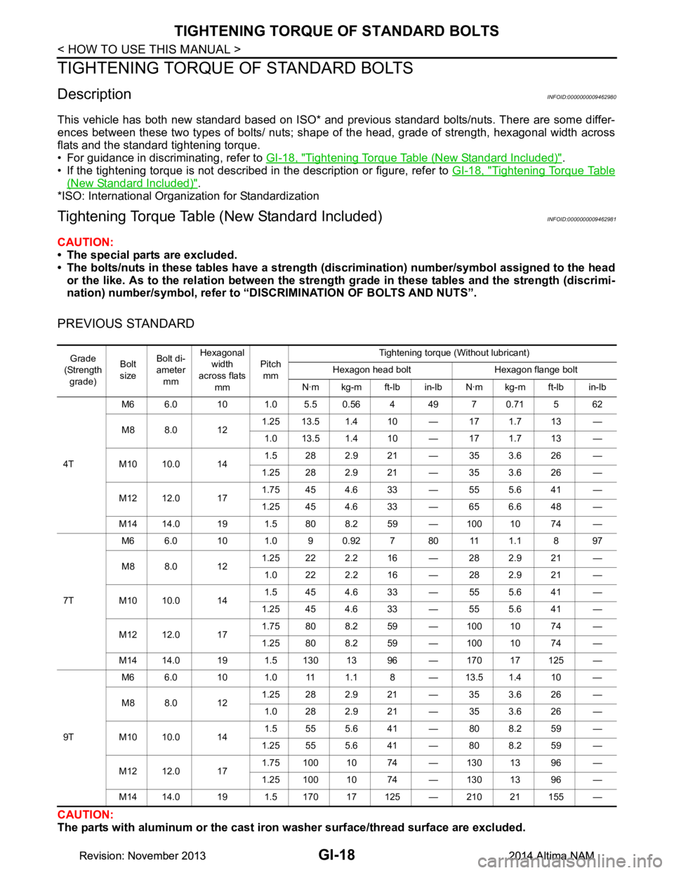
DescriptionINFOID:0000000009462980
This vehicle has both new standard based on ISO* and previous standard bolts/nuts. There are some differ-
ences between these two types of bolts/ nuts; shape of the head, grade of strength, hexagonal width across
flats and the standard tightening torque.
• For guidance in discriminating, refer to GI-18, "Tightening Torque Table (New Standard Included)"
.
• If the tightening torque is not described in the description or figure, refer to GI-18, "Tightening Torque Table
(New Standard Included)".
*ISO: International Organization for Standardization
Tightening Torque Tabl e (New Standard Included)INFOID:0000000009462981
CAUTION:
• The special parts are excluded.
• The bolts/nuts in these tables have a strength (d iscrimination) number/symbol assigned to the head
or the like. As to the relation between the stre ngth grade in these tables and the strength (discrimi-
nation) number/symbol, refer to “DISCRIMINATION OF BOLTS AND NUTS”.
PREVIOUS STANDARD
CAUTION:
The parts with aluminum or the cast iron washer surface/thread surface are excluded.
Grade
(Strength
grade) Bolt
size Bolt di-
ameter
mm Hexagonal
width
across flats mm Pitch
mm Tightening torque (Without lubricant)
Hexagon head bolt Hexagon flange bolt
N·m kg-m ft-lb in-lb N·m kg-m ft-lb in-lb
4T M6 6.0 10 1.0 5.5 0.56 4 49 7 0.71 5 62
M8 8.0 12 1.25 13.5 1.4 10 — 17 1.7 13 —
1.0 13.5 1.4 10 — 17 1.7 13 —
M10 10.0 14 1.5 28 2.9 21 — 35 3.6 26 —
1.25 28 2.9 21 — 35 3.6 26 —
M12 12.0 17 1.75 45 4.6 33 — 55 5.6 41 —
1.25 45 4.6 33 — 65 6.6 48 —
M14 14.0 19 1.5 80 8.2 59 — 100 10 74 —
7T M6 6.0 10 1.0 9 0.92 7 80 11 1.1 8 97
M8 8.0 12 1.25 22 2.2 16 — 28 2.9 21 —
1.0 22 2.2 16 — 28 2.9 21 —
M10 10.0 14 1.5 45 4.6 33 — 55 5.6 41 —
1.25 45 4.6 33 — 55 5.6 41 —
M12 12.0 17 1.75 80 8.2 59 — 100 10 74 —
1.25 80 8.2 59 — 100 10 74 —
M14 14.0 19 1.5 130 13 96 — 170 17 125 —
9T M6 6.0 10 1.0 11 1.1 8 — 13.5 1.4 10 —
M8 8.0 12 1.25 28 2.9 21 — 35 3.6 26 —
1.0 28 2.9 21 — 35 3.6 26 —
M10 10.0 14 1.5 55 5.6 41 — 80 8.2 59 —
1.25 55 5.6 41 — 80 8.2 59 —
M12 12.0 17 1.75 100 10 74 — 130 13 96 —
1.25 100 10 74 — 130 13 96 —
M14 14.0 19 1.5 170 17 125 — 210 21 155 —
Revision: November 20132014 Altima NAMRevision: November 20132014 Altima NAM
Page 2547 of 4801

TIGHTENING TORQUE OF STANDARD BOLTSGI-19
< HOW TO USE THIS MANUAL >
C
D E
F
G H
I
J
K L
M B
GI
N
O P
NEW STANDARD BASED ON ISO
CAUTION:
1. Use tightening torque with lubricant for the new standard bolts/nuts in principle. Friction coeffi- cient stabilizer is applied to the new standard bolts/nuts.
2. However, use tightening torque wi thout lubricant for the following cases. Friction coefficient stabi-
lizer is not applied to the following bolts/nuts.
- Grade 4.8, M6 size bolt, Co nical spring washer installed
- Paint removing nut (Size M6 and M8) for fixing with weld bolt
Grade
(Strength grade) Bolt
size Bolt di-
ameter mm Hexagonal
width
across flats
mm Pitch
mm Tightening torque
Hexagon head bolt Hexagon flange bolt
N·m kg-m ft-lb in-lb N·m kg-m ft-lb in-lb
4.8
(Without
lubricant) M6 6.0 10 1.0 5.5 0.56 4 49 7 0.71 5 62
M8 8.0 13 1.25 13.5 1.4 10 — 17 1.7 13 —
1.0 13.5 1.4 10 — 17 1.7 13 —
M10 10.0 16 1.5 282.921 — 353.626 —
1.25 28 2.9 21 — 35 3.6 26 —
M12 12.0 18 1.75 45 4.6 33 — 55 5.6 41 —
1.25 45 4.6 33 — 65 6.6 48 —
M14 14.0 21 1.5 80 8.2 59 — 100 10 74 —
4.8
(With lu-
bricant) M6 6.0 10 1.0 40.413 355.50.564 49
M8 8.0 13 1.25 11 1.1 8 — 13.5 1.4 10 —
1.0 11 1.1 8 — 13.5 1.4 10 —
M10 10.0 16 1.5 222.216 — 282.921 —
1.25 22 2.2 16 — 28 2.9 21 —
M12 12.0 18 1.75 35 3.6 26 — 45 4.6 33 —
1.25 35 3.6 26 — 45 4.6 33 —
M14 14.0 21 1.5 65 6.6 48 — 80 8.2 59 —
8.8
(With lu-
bricant) M6 6.0 10 1.0 8 0.82 6 71 10 1.0 7 89
M8 8.0 13 1.25 21 2.1 15 — 25 2.6 18 —
1.0 212.115 — 252.618 —
M10 10.0 16 1.5 404.130 — 505.137 —
1.25 40 4.1 30 — 50 5.1 37 —
M12 12.0 18 1.75 70 7.1 52 — 85 8.7 63 —
1.25 70 7.1 52 — 85 8.7 63 —
M14 14.0 21 1.5 120 12 89 — 140 14 103 —
10.9
(With lu-
bricant) M6 6.0 10 1.0 10 1.0 7 89 12 1.2 9 106
M8 8.0 13 1.25 27 2.8 20 — 32 3.3 24 —
1.0 272.820 — 323.324 —
M10 10.0 16 1.5 555.641 — 656.648 —
1.25 55 5.6 41 — 65 6.6 48 —
M12 12.0 18 1.75 95 9.7 70 — 110 11 81 —
1.25 95 9.7 70 — 110 11 81 —
M14 14.0 21 1.5 160 16 118 — 180 18 133 —
Revision: November 20132014 Altima NAMRevision: November 20132014 Altima NAM
Page 2548 of 4801
GI-20
< HOW TO USE THIS MANUAL >
TIGHTENING TORQUE OF STANDARD BOLTS
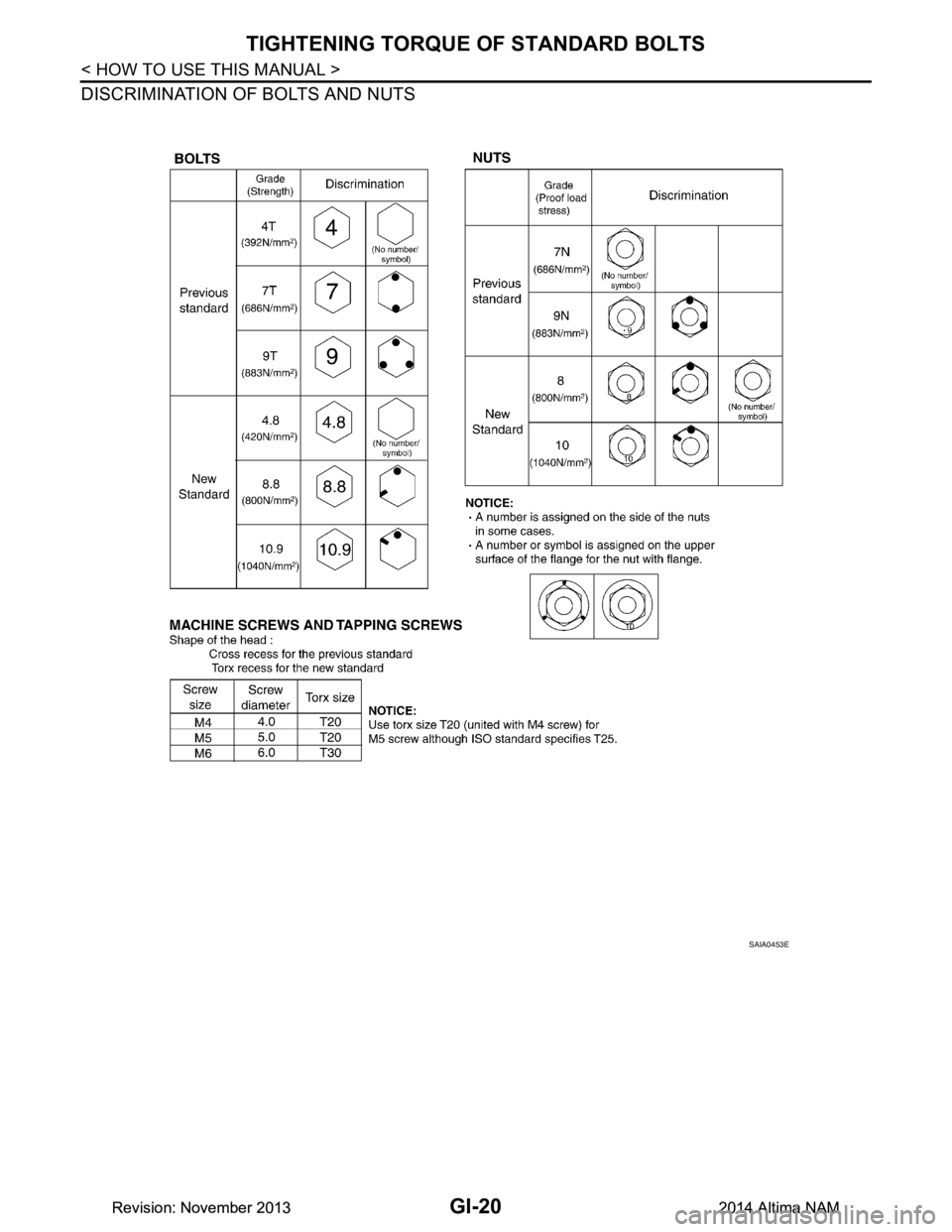
DISCRIMINATION OF BOLTS AND NUTS
SAIA0453E
Revision: November 20132014 Altima NAMRevision: November 20132014 Altima NAM
Page 2583 of 4801

PRECAUTIONSGW-3
< PRECAUTION >
C
D E
F
G H
I
J
L
M A
B
GW
N
O P
• When removing (disengaging) components with a screwdriver or similar tool, be sure to wrap the component with a shop cloth or vinyl tape to protect it.
• Protect the removed parts with a shop cloth and prevent them from being dropped.
• Replace a deformed or damaged clip.
• If a part is specified as a non-reusabl e part, always replace it with a new one.
• Be sure to tighten bolts and nuts securely to the specified torque.
• After installation is complete, be sure to check that each part works properly.
• Follow the steps below to clean components:
- Water soluble dirt:
• Dip a soft cloth into lukewarm water, wring the water out of the cloth and wipe the dirty area.
• Then rub with a soft, dry cloth.
-Oily dirt:
• Dip a soft cloth into lukewarm water with mild detergent (concentration: within 2 to 3%) and wipe the dirty
area.
• Then dip a cloth into fresh water, wring the water out of the cloth and wipe the detergent off.
• Then rub with a soft, dry cloth.
- Do not use organic solvent such as thinner, benzene, alcohol or gasoline.
- For genuine leather seats, use a genuine leather seat cleaner.
Revision: November 20132014 Altima NAM
Page 2609 of 4801
PRECAUTIONSHA-3
< PRECAUTION >
C
D E
F
G H
J
K L
M A
B
HA
N
O P
PRECAUTION
PRECAUTIONS
Precaution for Supplemental Restraint System (SRS) "AIR BAG" and "SEAT BELT
PRE-TENSIONER"
INFOID:0000000009951784
The Supplemental Restraint System such as “A IR BAG” and “SEAT BELT PRE-TENSIONER”, used along
with a front seat belt, helps to reduce the risk or severi ty of injury to the driver and front passenger for certain
types of collision. Information necessary to service t he system safely is included in the SR and SB section of
this Service Manual.
WARNING:
• To avoid rendering the SRS inoper ative, which could increase the risk of personal injury or death in
the event of a collision which would result in air bag inflation, all maintenance must be performed by
an authorized NISSAN/INFINITI dealer.
• Improper maintenance, including in correct removal and installation of the SRS, can lead to personal
injury caused by unintentional act ivation of the system. For removal of Spiral Cable and Air Bag
Module, see the SR section.
• Do not use electrical test equipm ent on any circuit related to the SRS unless instructed to in this
Service Manual. SRS wiring harnesses can be identi fied by yellow and/or orange harnesses or har-
ness connectors.
PRECAUTIONS WHEN USING POWER TOOLS (AIR OR ELECTRIC) AND HAMMERS
WARNING:
• When working near the Airbag Diagnosis Sensor Un it or other Airbag System sensors with the Igni-
tion ON or engine running, DO NOT use air or el ectric power tools or strike near the sensor(s) with a
hammer. Heavy vibration could activate the sensor( s) and deploy the air bag(s), possibly causing
serious injury.
• When using air or electric power tools or hammers , always switch the Ignition OFF, disconnect the
battery and wait at least three mi nutes before performing any service.
Precaution for WorkINFOID:0000000009463909
• When removing or disassembling each component, be ca reful not to damage or deform it. If a component
may be subject to interference, be sure to protect it with a shop cloth.
• When removing (disengaging) components with a screwdriver or similar tool, be sure to wrap the component with a shop cloth or vinyl tape to protect it.
• Protect the removed parts with a shop cloth and prevent them from being dropped.
• Replace a deformed or damaged clip.
• If a part is specified as a non-reusabl e part, always replace it with a new one.
• Be sure to tighten bolts and nuts securely to the specified torque.
• After installation is complete, be sure to check that each part works properly.
• Follow the steps below to clean components:
- Water soluble dirt:
• Dip a soft cloth into lukewarm water, wring the water out of the cloth and wipe the dirty area.
• Then rub with a soft, dry cloth.
-Oily dirt:
• Dip a soft cloth into lukewarm water with mild detergent (concentration: within 2 to 3%) and wipe the dirty area.
• Then dip a cloth into fresh water, wring the water out of the cloth and wipe the detergent off.
• Then rub with a soft, dry cloth.
- Do not use organic solvent such as thinner, benzene, alcohol or gasoline.
- For genuine leather seats, use a genuine leather seat cleaner.
Precaution for Workin g with HFC-134a (R-134a)INFOID:0000000009463910
WARNING:
• CFC-12 (R-12) refrigerant and HFC-134a (R-134a) refr igerant are not compatible. If the refrigerants
are mixed compressor failure is likely to occur. Refer to HA-21, "Leak Test"
. To determine the purity
of HFC-134a (R-134a) in the vehicle and recovery tank, use Refrigerant Recovery/Recycling Recharg-
ing equipment and Refrigerant Identifier.
Revision: November 20132014 Altima NAM
Page 2612 of 4801
HA-6
< PRECAUTION >
PRECAUTIONS
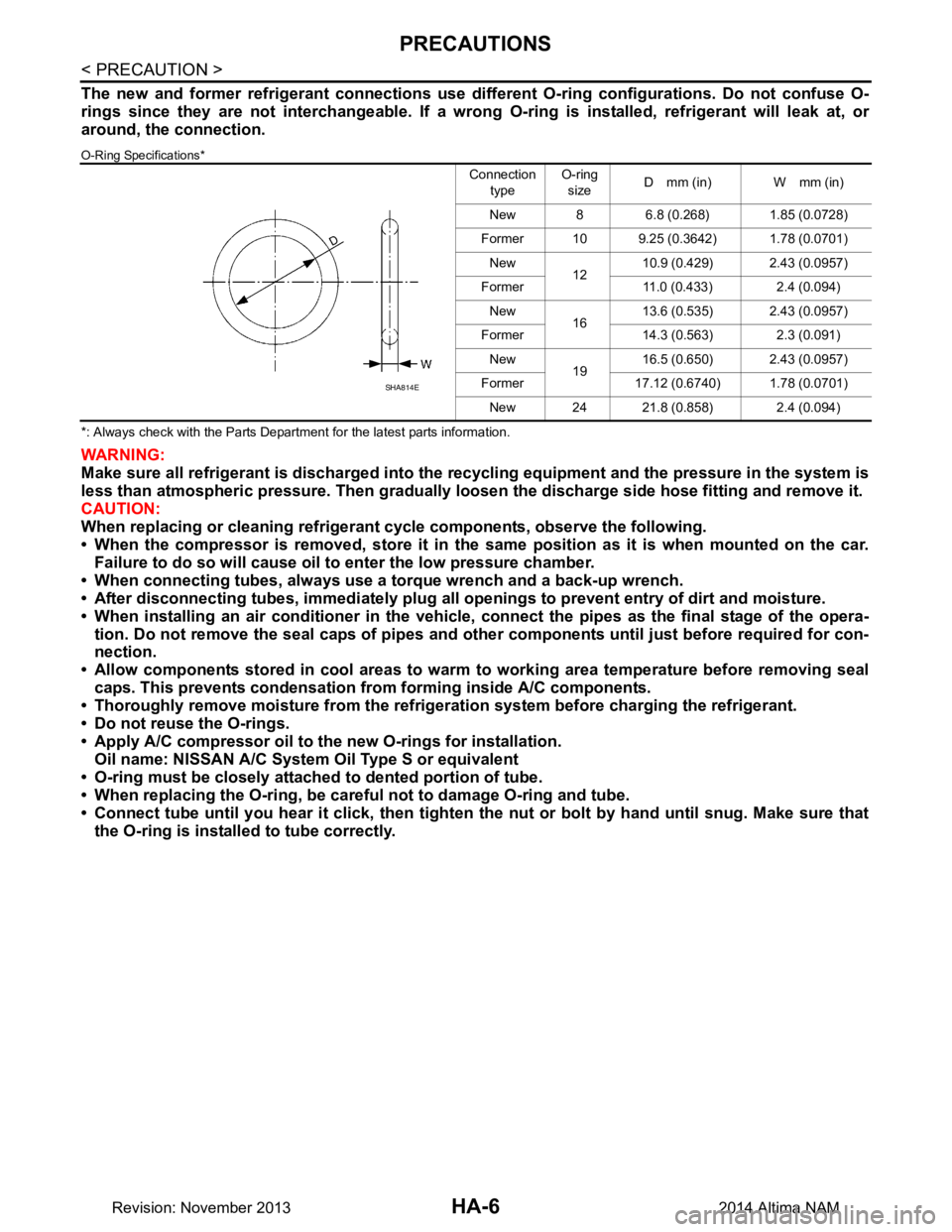
The new and former refrigerant connections use different O-ring configurations. Do not confuse O-
rings since they are not interchangeable. If a wrong O-ring is installed, refrigerant will leak at, or
around, the connection.
O-Ring Specifications*
*: Always check with the Parts Department for the latest parts information.
WARNING:
Make sure all refrigerant is discharged into the recycling equipment and the pressure in the system is
less than atmospheric pressure. Then gradually loo sen the discharge side hose fitting and remove it.
CAUTION:
When replacing or cleaning refrigeran t cycle components, observe the following.
• When the compressor is removed, store it in the same position as it is when mounted on the car.
Failure to do so will cause oil to enter the low pressure chamber.
• When connecting tubes, always use a torque wrench and a back-up wrench.
• After disconnecting tubes, immedi ately plug all openings to prevent entry of dirt and moisture.
• When installing an air conditioner in the vehicle, connect the pipes as the final stage of the opera-
tion. Do not remove the seal caps of pipes and othe r components until just before required for con-
nection.
• Allow components stored in cool areas to warm to working area temperature before removing seal
caps. This prevents condensation from forming inside A/C components.
• Thoroughly remove moisture from the refrigerat ion system before charging the refrigerant.
• Do not reuse the O-rings.
• Apply A/C compressor oil to th e new O-rings for installation.
Oil name: NISSAN A/C System Oil Type S or equivalent
• O-ring must be closely attached to dented portion of tube.
• When replacing the O-ring, be careful not to damage O-ring and tube.
• Connect tube until you hear it cl ick, then tighten the nut or bolt by hand until snug. Make sure that
the O-ring is installed to tube correctly.
Connection
type O-ring
size D mm (in) W mm (in)
New 8 6.8 (0.268) 1.85 (0.0728)
Former 10 9.25 (0.3642) 1.78 (0.0701) New 1210.9 (0.429) 2.43 (0.0957)
Former 11.0 (0.433) 2.4 (0.094) New 1613.6 (0.535) 2.43 (0.0957)
Former 14.3 (0.563) 2.3 (0.091) New 1916.5 (0.650) 2.43 (0.0957)
Former 17.12 (0.6740) 1.78 (0.0701) New 24 21.8 (0.858) 2.4 (0.094)
SHA814E
Revision: November 20132014 Altima NAM
Page 2613 of 4801
PRECAUTIONSHA-7
< PRECAUTION >
C
D E
F
G H
J
K L
M A
B
HA
N
O P
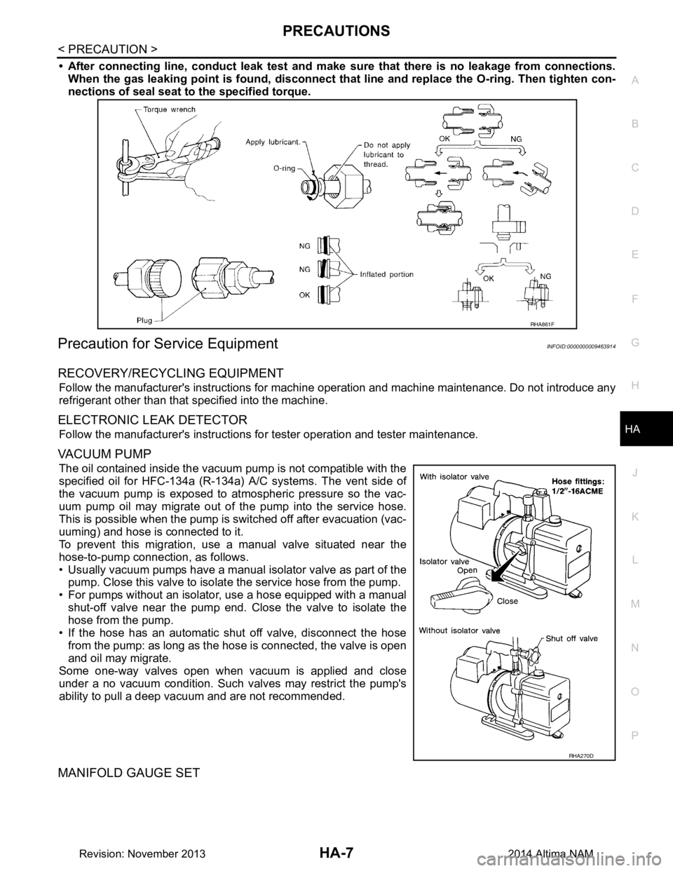
• After connecting line, conduct leak test and make sure that there is no leakage from connections.
When the gas leaking point is f ound, disconnect that line and replace the O-ring. Then tighten con-
nections of seal seat to the specified torque.
Precaution for Service EquipmentINFOID:0000000009463914
RECOVERY/RECYCLING EQUIPMENT
Follow the manufacturer's instructions for machine operation and machine maintenance. Do not introduce any
refrigerant other than that specified into the machine.
ELECTRONIC LEAK DETECTOR
Follow the manufacturer's instructions fo r tester operation and tester maintenance.
VACUUM PUMP
The oil contained inside the vacuum pump is not compatible with the
specified oil for HFC-134a (R-134a) A/C systems. The vent side of
the vacuum pump is exposed to atmospheric pressure so the vac-
uum pump oil may migrate out of the pump into the service hose.
This is possible when the pump is switched off after evacuation (vac-
uuming) and hose is connected to it.
To prevent this migration, use a manual valve situated near the
hose-to-pump connection, as follows.
• Usually vacuum pumps have a manual isolator valve as part of the
pump. Close this valve to isolate the service hose from the pump.
• For pumps without an isolator, use a hose equipped with a manual shut-off valve near the pump end. Close the valve to isolate the
hose from the pump.
• If the hose has an automatic shut off valve, disconnect the hose from the pump: as long as the hos e is connected, the valve is open
and oil may migrate.
Some one-way valves open when vacuum is applied and close
under a no vacuum condition. Such valves may restrict the pump's
ability to pull a deep vacuum and are not recommended.
MANIFOLD GAUGE SET
RHA861F
RHA270D
Revision: November 20132014 Altima NAM