2014 NISSAN TEANA torque
[x] Cancel search: torquePage 2241 of 4801
![NISSAN TEANA 2014 Service Manual
CYLINDER BLOCKEM-243
< UNIT DISASSEMBLY AND ASSEMBLY > [VQ35DE]
C
D E
F
G H
I
J
K L
M A
EM
NP
O
Connecting Rod Bearing (Big End)
1. Install the connecting rod bearing to the connecting rod and cap. NISSAN TEANA 2014 Service Manual
CYLINDER BLOCKEM-243
< UNIT DISASSEMBLY AND ASSEMBLY > [VQ35DE]
C
D E
F
G H
I
J
K L
M A
EM
NP
O
Connecting Rod Bearing (Big End)
1. Install the connecting rod bearing to the connecting rod and cap.](/manual-img/5/57390/w960_57390-2240.png)
CYLINDER BLOCKEM-243
< UNIT DISASSEMBLY AND ASSEMBLY > [VQ35DE]
C
D E
F
G H
I
J
K L
M A
EM
NP
O
Connecting Rod Bearing (Big End)
1. Install the connecting rod bearing to the connecting rod and cap.
2. Install the connecting rod cap to the connecti ng rod. Tighten to specification. Refer to EM-224, "Disassem-
bly and Assembly".
3. Measure the inner diameter (C) of each connecting rod (big end) as shown.
4. Measure the outer diameter (Dp) of each crankshaft pin journal.
5. Calculate the connecting rod bearing clearance. Connecting rod bearing clearance = (C) - (Dp)
6. If the calculated clearance exceeds the specified limit, replace the bearings.
7. If the clearance cannot be adjusted within the standard of any bearing, grind the crankshaft journal and use undersized bear-
ings.
8. If the crankshaft is replaced with a new one, select the connect-
ing rod bearings according to the following table:
Connecting Rod Bearing Grad e Number (Identification
Color)
These numbers are punched in eit her Arabic or Roman numer-
als.
Method B (Using Plastigage)
• Remove oil and dust on the crankshaft pin and the surfaces of each bearing completely.
• Cut a Plastigage slightly shorter than the bearing width, and place it in crankshaft axial direction, avoiding oil holes.
• Install the connecting rod bearings to the connecting rod cap, and tighten the connecting rod nuts to the specified torque.
CAUTION:
Do not rotate the crankshaft.
• Remove the connecting rod cap and bearings, and using the scale on the Plastigage bag, measure the Plastigage width.
NOTE:
The procedure when the measured value exceeds the repair limit
is same as that described in "Method A (Using Bore Gauge and Micrometer)".
DRIVE PLATE RUNOUT
AEM027
Standard : 0.020 - 0.045 mm (0.0008 - 0.0018 in)
Limit : 0.070 mm (0.0028 in)
AEM034
Crankshaft pin journal grade number Connecting rod bearing grade
number
0 0 (black)
1 1 (brown)
2 2 (green)
SEM452G
SEM142
Revision: November 20132014 Altima NAM
Page 2242 of 4801
![NISSAN TEANA 2014 Service Manual
EM-244
< UNIT DISASSEMBLY AND ASSEMBLY >[VQ35DE]
CYLINDER BLOCK
Runout (Total Indicator Reading):
CAUTION:
• The signal plate is built into the drive assembly. Be careful not
to damage the signa NISSAN TEANA 2014 Service Manual
EM-244
< UNIT DISASSEMBLY AND ASSEMBLY >[VQ35DE]
CYLINDER BLOCK
Runout (Total Indicator Reading):
CAUTION:
• The signal plate is built into the drive assembly. Be careful not
to damage the signa](/manual-img/5/57390/w960_57390-2241.png)
EM-244
< UNIT DISASSEMBLY AND ASSEMBLY >[VQ35DE]
CYLINDER BLOCK
Runout (Total Indicator Reading):
CAUTION:
• The signal plate is built into the drive assembly. Be careful not
to damage the signal plate, particularly the teeth.
• Check the drive plate and sign al plate for deformation or
cracks.
• Keep any magnetized objects away from th e signal plate, particularly the teeth.
OIL JET
• Check nozzle for deformation and damage.
• Blow compressed air from nozzle, and check for clogs.
• If it is not operating properly, replace oil jet.
OIL JET RELIEF VALVE
• Using a clean plastic stick, press check valve in oil jet relief valve. Make sure that valve moves smoothly with proper reaction force.
• If it is not operating properly, replace oil jet relief valve.
Dowel Pin AlignmentINFOID:0000000009460583
REMOVAL
1. Use suitable tool to lock the drive plate and match mark (A) before removing the bolts.
CAUTION:
Do not damage the ring gear t eeth, or the signal plate teeth
behind the ring gear, when setting Tool. Drive plate
torque converter sur-
face : less than 0.35 mm (.0138 in)
Ring gear : less than 0.5 mm (.0197 in)
SEM849EB
SEM760G
EMU0468D
ALBIA0522ZZ
Revision: November 20132014 Altima NAM
Page 2255 of 4801
![NISSAN TEANA 2014 Service Manual
SERVICE DATA AND SPECIFICATIONS (SDS)EM-257
< SERVICE DATA AND SPECIFICATIONS (SDS) [VQ35DE]
C
D E
F
G H
I
J
K L
M A
EM
NP
O
CONNECTING ROD BEARING OIL CLEARANCE
Unit: mm (in)
*: Actual clearance
D NISSAN TEANA 2014 Service Manual
SERVICE DATA AND SPECIFICATIONS (SDS)EM-257
< SERVICE DATA AND SPECIFICATIONS (SDS) [VQ35DE]
C
D E
F
G H
I
J
K L
M A
EM
NP
O
CONNECTING ROD BEARING OIL CLEARANCE
Unit: mm (in)
*: Actual clearance
D](/manual-img/5/57390/w960_57390-2254.png)
SERVICE DATA AND SPECIFICATIONS (SDS)EM-257
< SERVICE DATA AND SPECIFICATIONS (SDS) [VQ35DE]
C
D E
F
G H
I
J
K L
M A
EM
NP
O
CONNECTING ROD BEARING OIL CLEARANCE
Unit: mm (in)
*: Actual clearance
Drive PlateINFOID:0000000009460594
Unit: mm (in)
*: Total indicator reading
Items Standard Limit
Connecting rod bearing oil clearance 0.020 - 0.045 (0.0010 - 0.0018)* 0.070 (0.0028)
Drive plate runout [TIR]* - on torque conver ter mounting surface Less than 0.35 (0.0138)
Drive plate runout [TIR]* - on ring gear 0.5 (0.0197)
Revision: November 20132014 Altima NAM
Page 2271 of 4801
PRECAUTIONSEXL-5
< PRECAUTION >
C
D E
F
G H
I
J
K
M A
B
EXL
N
O P
Precaution for WorkINFOID:0000000009463539
• When removing or disassembling each component, be ca reful not to damage or deform it. If a component
may be subject to interference, be sure to protect it with a shop cloth.
• When removing (disengaging) components with a screwdriver or similar tool, be sure to wrap the component
with a shop cloth or vinyl tape to protect it.
• Protect the removed parts with a shop cloth and prevent them from being dropped.
• Replace a deformed or damaged clip.
• If a part is specified as a non-reusabl e part, always replace it with a new one.
• Be sure to tighten bolts and nuts securely to the specified torque.
• After installation is complete, be sure to check that each part works properly.
• Follow the steps below to clean components:
- Water soluble dirt:
• Dip a soft cloth into lukewarm water, wring the water out of the cloth and wipe the dirty area.
• Then rub with a soft, dry cloth.
-Oily dirt:
• Dip a soft cloth into lukewarm water with mild detergent (concentration: within 2 to 3%) and wipe the dirty
area.
• Then dip a cloth into fresh water, wring the water out of the cloth and wipe the detergent off.
• Then rub with a soft, dry cloth.
- Do not use organic solvent such as thinner, benzene, alcohol or gasoline.
- For genuine leather seats, use a genuine leather seat cleaner.
Revision: November 20132014 Altima NAMRevision: November 20132014 Altima NAM
Page 2417 of 4801
PRECAUTIONSEXT-3
< PRECAUTION >
C
D E
F
G H
I
J
L
M A
B
EXT
N
O P
PRECAUTION
PRECAUTIONS
Precaution for Supplemental Restraint System (SRS) "AIR BAG" and "SEAT BELT
PRE-TENSIONER"
INFOID:0000000009951571
The Supplemental Restraint System such as “A IR BAG” and “SEAT BELT PRE-TENSIONER”, used along
with a front seat belt, helps to reduce the risk or severi ty of injury to the driver and front passenger for certain
types of collision. Information necessary to service t he system safely is included in the SR and SB section of
this Service Manual.
WARNING:
• To avoid rendering the SRS inoper ative, which could increase the risk of personal injury or death in
the event of a collision which would result in air bag inflation, all maintenance must be performed by
an authorized NISSAN/INFINITI dealer.
• Improper maintenance, including in correct removal and installation of the SRS, can lead to personal
injury caused by unintentional act ivation of the system. For removal of Spiral Cable and Air Bag
Module, see the SR section.
• Do not use electrical test equipm ent on any circuit related to the SRS unless instructed to in this
Service Manual. SRS wiring harnesses can be identi fied by yellow and/or orange harnesses or har-
ness connectors.
PRECAUTIONS WHEN USING POWER TOOLS (AIR OR ELECTRIC) AND HAMMERS
WARNING:
• When working near the Airbag Diagnosis Sensor Un it or other Airbag System sensors with the Igni-
tion ON or engine running, DO NOT use air or el ectric power tools or strike near the sensor(s) with a
hammer. Heavy vibration could activate the sensor( s) and deploy the air bag(s), possibly causing
serious injury.
• When using air or electric power tools or hammers , always switch the Ignition OFF, disconnect the
battery and wait at least three mi nutes before performing any service.
Precaution for Procedure without Cowl Top CoverINFOID:0000000009460986
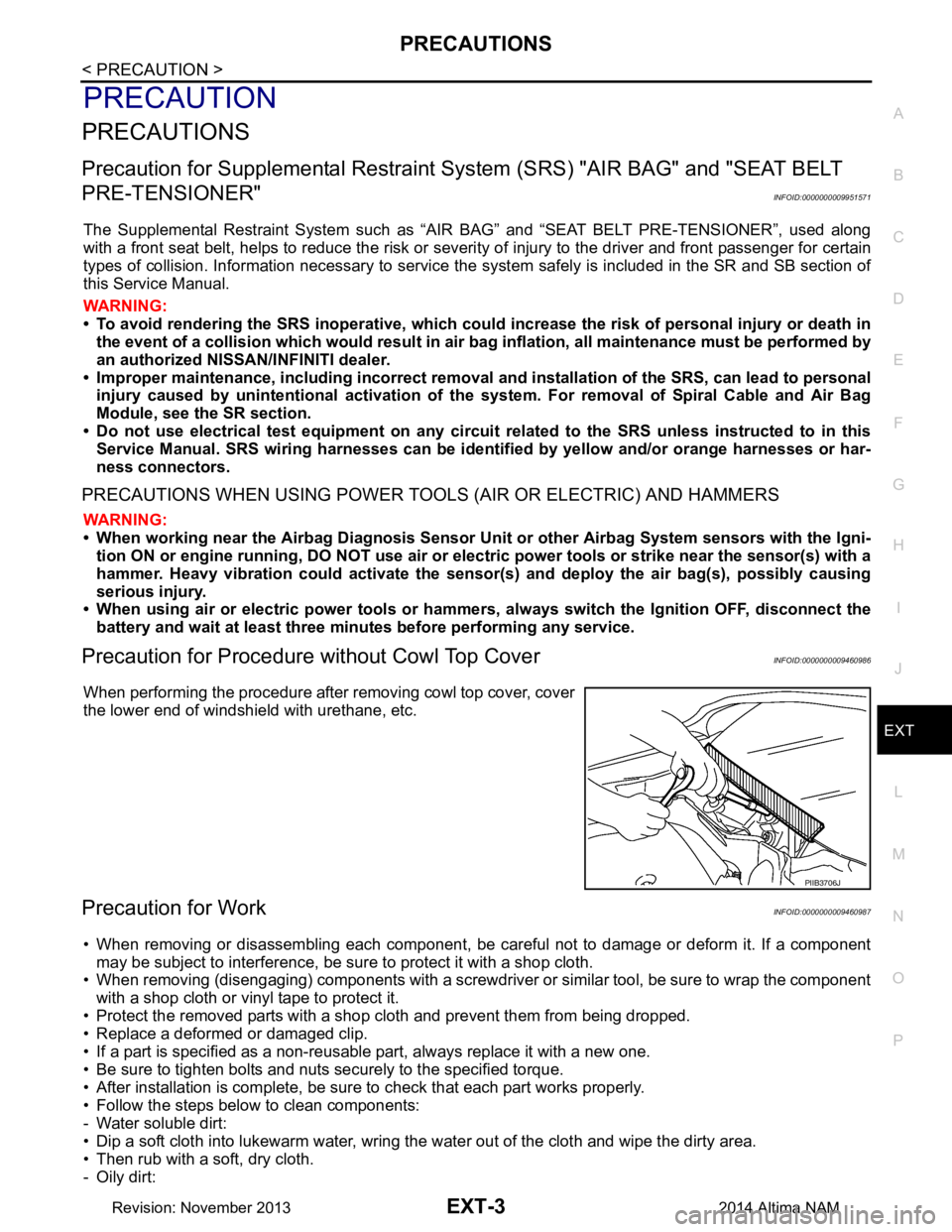
When performing the procedure after removing cowl top cover, cover
the lower end of windshield with urethane, etc.
Precaution for WorkINFOID:0000000009460987
• When removing or disassembling each component, be ca reful not to damage or deform it. If a component
may be subject to interference, be sure to protect it with a shop cloth.
• When removing (disengaging) components with a screwdriver or similar tool, be sure to wrap the component with a shop cloth or vinyl tape to protect it.
• Protect the removed parts with a shop cloth and prevent them from being dropped.
• Replace a deformed or damaged clip.
• If a part is specified as a non-reusabl e part, always replace it with a new one.
• Be sure to tighten bolts and nuts securely to the specified torque.
• After installation is complete, be sure to check that each part works properly.
• Follow the steps below to clean components:
- Water soluble dirt:
• Dip a soft cloth into lukewarm water, wring the water out of the cloth and wipe the dirty area.
• Then rub with a soft, dry cloth.
-Oily dirt:
PIIB3706J
Revision: November 20132014 Altima NAM
Page 2482 of 4801
FL-2
< PRECAUTION >
PRECAUTIONS
PRECAUTION
PRECAUTIONS
Precaution for Supplemental Restraint System (SRS) "AIR BAG" and "SEAT BELT
PRE-TENSIONER"
INFOID:0000000009951691
The Supplemental Restraint System such as “A IR BAG” and “SEAT BELT PRE-TENSIONER”, used along
with a front seat belt, helps to reduce the risk or severi ty of injury to the driver and front passenger for certain
types of collision. Information necessary to service the system safely is included in the SR and SB section of
this Service Manual.
WARNING:
• To avoid rendering the SRS inopera tive, which could increase the risk of personal injury or death in
the event of a collision which would result in air bag inflation, all maintenance must be performed by
an authorized NISS AN/INFINITI dealer.
• Improper maintenance, including in correct removal and installation of the SRS, can lead to personal
injury caused by unintent ional activation of the system. For re moval of Spiral Cable and Air Bag
Module, see the SR section.
• Do not use electrical test equipmen t on any circuit related to the SRS unless instructed to in this
Service Manual. SRS wiring harn esses can be identified by yellow and/or orange harnesses or har-
ness connectors.
PRECAUTIONS WHEN USING POWER TOOLS (AIR OR ELECTRIC) AND HAMMERS
WARNING:
• When working near the Airbag Diagnosis Sensor Unit or other Airbag System sensors with the Igni-
tion ON or engine running, DO NOT use air or electri c power tools or strike near the sensor(s) with a
hammer. Heavy vibration could activate the sensor( s) and deploy the air bag(s), possibly causing
serious injury.
• When using air or electric power tools or hammers , always switch the Ignition OFF, disconnect the
battery and wait at least three minutes before performing any service.
General PrecautionINFOID:0000000009460597
WARNING:
When replacing fuel line parts, be sure to observe the following.
• Put a “CAUTION: FLAMMABLE” sign in the work area.
• Be sure to work in a well ventilated area and have a CO
2 fire extinguisher.
• Do not smoke while working on the fuel system. Keep open flames and sparks away from the work
area.
CAUTION:
• Before removing fuel line parts, carry out the following procedures:
- Put drained fuel in an explosi on-proof container and put the lid on securely. Keep the container in
safe area.
- Release fuel pressure from the fuel lines. Refer to EC-182, "Work Procedure"
(QR25DE), EC-687,
"Work Procedure" (VQ35DE).
- Disconnect the battery ground cable.
• Always replace O-rings and clamps with new ones.
• Do not kink or twist tubes when they are being installed.
• Do not tighten hose clamps excessi vely to avoid damaging hoses.
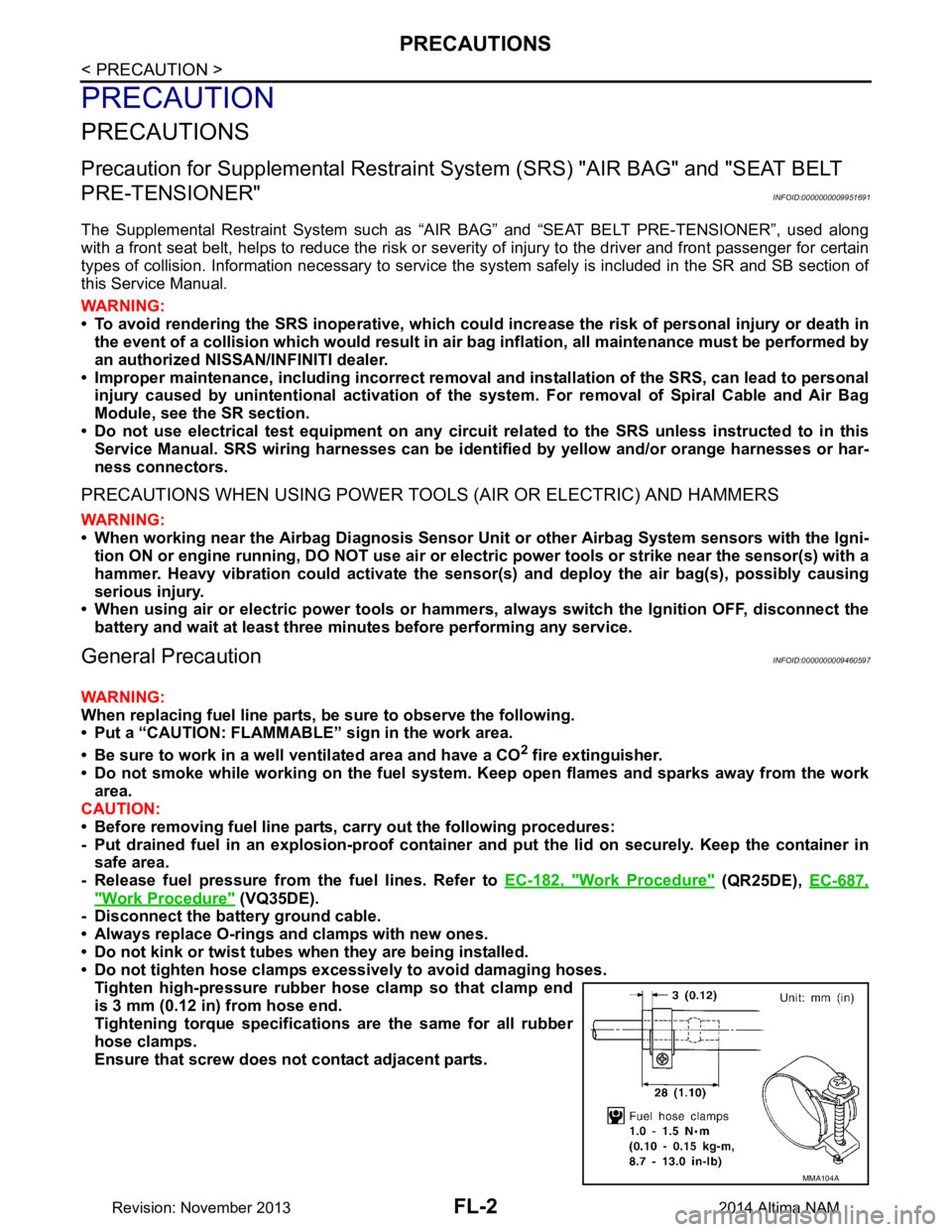
Tighten high-pressure rubber hose clamp so that clamp end
is 3 mm (0.12 in) from hose end.
Tightening torque specificati ons are the same for all rubber
hose clamps.
Ensure that screw does not contact adjacent parts.
MMA104A
Revision: November 20132014 Altima NAM
Page 2492 of 4801
FL-12
< REMOVAL AND INSTALLATION >
FUEL TANK
8. Remove rear wheel and tire using power tool. Refer to WT-55, "Adjustment".
9. Remove rear brake pads. Refer to BR-38, "BRAKE PAD : Removal and Installation"
.
10. Remove rear torque members and rear disc brake rotor.
11. Disconnect rear parking brake shoe, and remove rear cables from toggle lever. Refer to PB-9, "Removal
and Installation".
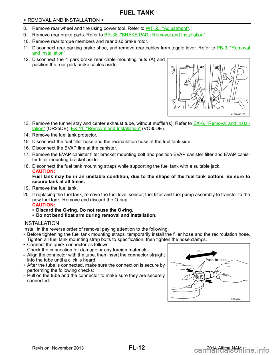
12. Disconnect the 4 park brake rear cable mounting nuts (A) and position the rear park brake cables aside.
13. Remove the tunnel stay and center exhaust tube, without muffler(s). Refer to EX-6, "Removal and Instal-
lation" (QR25DE), EX-11, "Removal and Installation" (VQ35DE).
14. Remove the fuel tank protector.
15. Disconnect the fuel filler hose and the recirculation hose at the fuel tank side.
16. Disconnect the EVAP line at the canister.
17. Remove the EVAP canister filter bracket mounti ng bolt and position EVAP canister filter and EVAP canis-
ter filter mounting bracket aside.
18. Disconnect the fuel tank mounting straps while supporting the fuel tank with a suitable jack. CAUTION:
Fuel tank may be in an unstable condition, due to the shape of the fuel tank bottom. Be sure to
secure tank at all times.
19. Remove the fuel tank.
20. If replacing the fuel tank, remove the fuel level sens or, fuel filter and fuel pump assembly to transfer to the
new fuel tank. Remove and discard the O-ring.
CAUTION:
• Discard the O-ring. Do not reuse the O-ring.
• Do not bend float arm during removal and installation.
INSTALLATION
Install in the reverse order of removal paying attention to the following.
• Before tightening the fuel tank mounting straps, tempor arily install the filler hose and the recirculation hose.
Tighten all fuel tank mounting strap bolts to specification, then tighten the hose clamps.
• Connect the quick connector as follows:
- Check the connection for damage or any foreign materials.
- Align the connector with the tube, then insert the connector straight into the tube until a click is heard.
• After the tube is connected, make sure the connection is secure by performing the following checks:
- Pull on the tube and the connector to make sure they are securely
connected.
ALBIA0901ZZ
SFE562A
Revision: November 20132014 Altima NAM
Page 2494 of 4801
FL-14
< REMOVAL AND INSTALLATION >
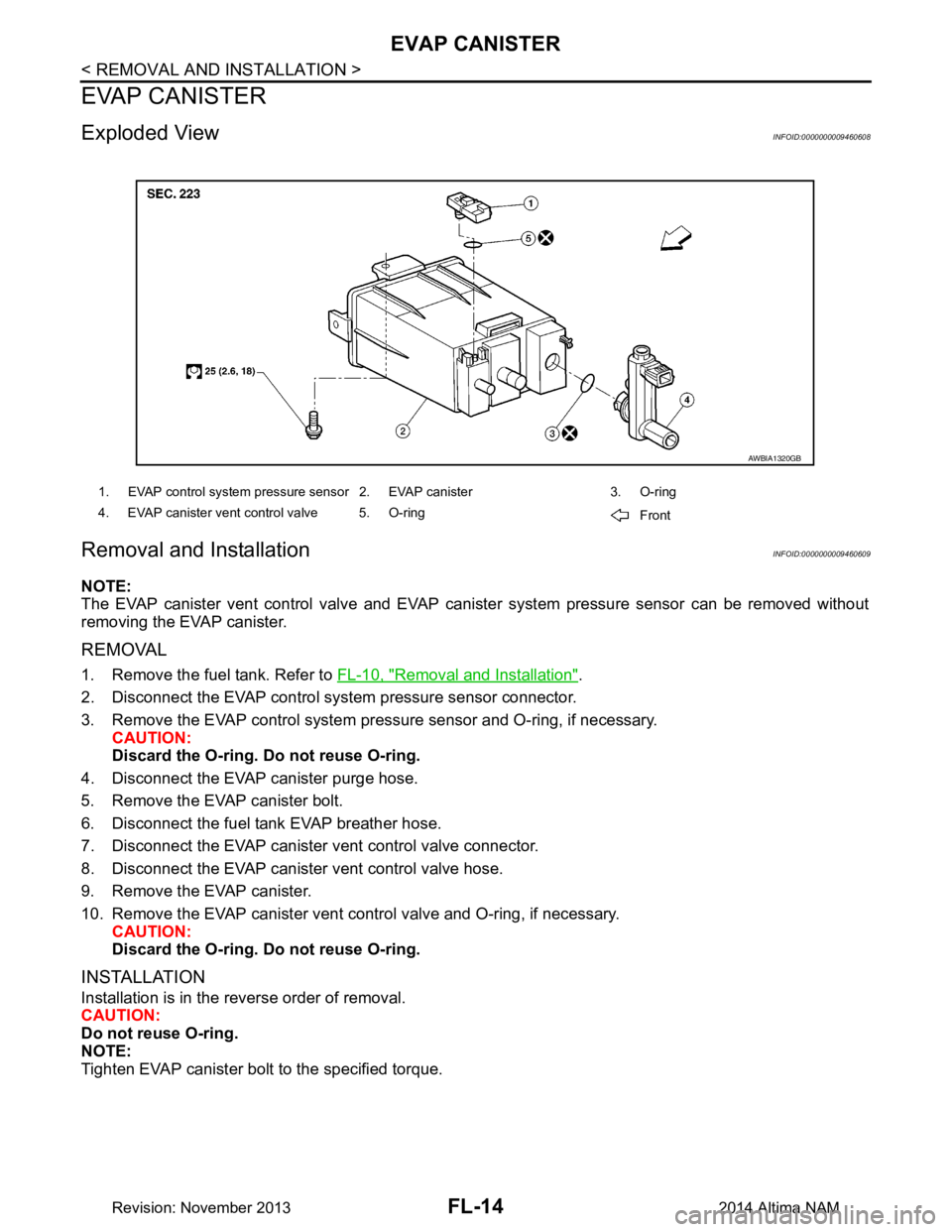
EVAP CANISTER
EVAP CANISTER
Exploded ViewINFOID:0000000009460608
Removal and InstallationINFOID:0000000009460609
NOTE:
The EVAP canister vent control valve and EVAP cani ster system pressure sensor can be removed without
removing the EVAP canister.
REMOVAL
1. Remove the fuel tank. Refer to FL-10, "Removal and Installation".
2. Disconnect the EVAP control system pressure sensor connector.
3. Remove the EVAP control system pressu re sensor and O-ring, if necessary.
CAUTION:
Discard the O-ring. Do not reuse O-ring.
4. Disconnect the EVAP canister purge hose.
5. Remove the EVAP canister bolt.
6. Disconnect the fuel tank EVAP breather hose.
7. Disconnect the EVAP canister vent control valve connector.
8. Disconnect the EVAP canister vent control valve hose.
9. Remove the EVAP canister.
10. Remove the EVAP canister vent c ontrol valve and O-ring, if necessary.
CAUTION:
Discard the O-ring. Do not reuse O-ring.
INSTALLATION
Installation is in the reverse order of removal.
CAUTION:
Do not reuse O-ring.
NOTE:
Tighten EVAP canister bolt to the specified torque.
1. EVAP control system pressure sensor 2. EVAP canister 3. O-ring
4. EVAP canister vent control valve 5. O-ring Front
AWBIA1320GB
Revision: November 20132014 Altima NAM