2014 NISSAN TEANA torque
[x] Cancel search: torquePage 3710 of 4801
MOONROOF UNIT ASSEMBLYRF-45
< REMOVAL AND INSTALLATION >
C
D E
F
G H
I
J
L
M A
B
RF
N
O P
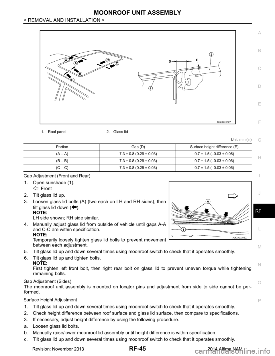
Unit: mm (in)
Gap Adjustment (Front and Rear)
1. Open sunshade (1). : Front
2. Tilt glass lid up.
3. Loosen glass lid bolts (A) (two each on LH and RH sides), then tilt glass lid down ( ).
NOTE:
LH side shown; RH side similar.
4. Manually adjust glass lid from outside of vehicle until gaps A-A
and C-C are within specification.
NOTE:
Temporarily loosely tighten glass lid bolts to prevent movement
between each adjustment.
5. Tilt glass lid up and down several times using moonr oof switch to check that it operates smoothly.
6. Tilt glass lid up and tighten bolts. NOTE:
First tighten left front bolt, then right rear bolt on glass lid to prevent uneven torque while tightening
remaining bolts.
Gap Adjustment (Sides)
The moonroof unit assembly is mounted on locator pi ns and adjustment from side to side cannot be per-
formed.
Surface Height Adjustment
1. Tilt glass lid up and down several times using moonr oof switch to check that it operates smoothly.
2. Check height difference between roof surface and glas s lid surface, then compare to specifications.
3. If necessary, adjust height difference by using the following procedure.
a. Loosen glass lid bolts.
b. Manually raise/lower moonroof lid assembly until height difference is within specification.
c. Tilt glass lid up and down several times using moonr oof switch to check that it operates smoothly.
1. Roof panel 2. Glass lid
ALKIA2280ZZ
Portion Gap (D) Surface height difference (E)
(A – A) 7.3 ± 0.8 (0.29 ± 0.03) 0.7 ± 1.5 (–0.03 ± 0.06)
(B – B) 7.3 ± 0.8 (0.29 ± 0.03) 0.7 ± 1.5 (–0.03 ± 0.06)
(C – C) 7.3 ± 0.8 (0.29 ± 0.03) 0.7 ± 1.5 (–0.03 ± 0.06)
ALKIA2724ZZ
Revision: November 20132014 Altima NAMRevision: November 20132014 Altima NAM
Page 3711 of 4801
RF-46
< REMOVAL AND INSTALLATION >
MOONROOF UNIT ASSEMBLY
d. Tighten glass lid bolts.NOTE:
First tighten left front bolt, then right rear bolt on glass lid to prevent uneven torque while tightening
remaining bolts.
e. After any adjustment, check moonroof operation and glass lid alignment.
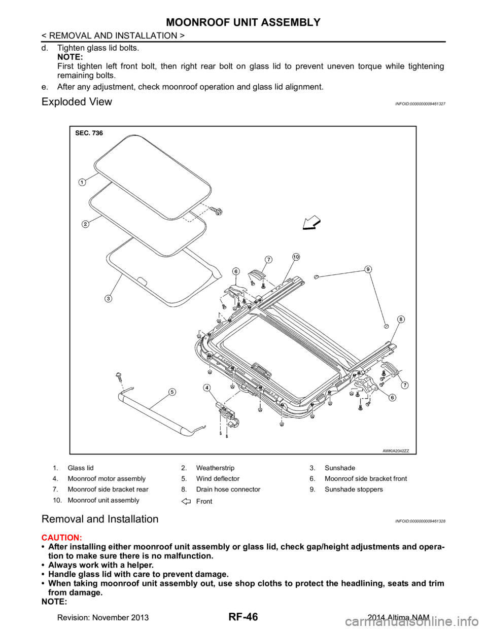
Exploded ViewINFOID:0000000009461327
Removal and InstallationINFOID:0000000009461328
CAUTION:
• After installing either moonro of unit assembly or glass lid, check gap/height adjustments and opera-
tion to make sure there is no malfunction.
• Always work with a helper.
• Handle glass lid with care to prevent damage.
• When taking moonroof unit assembly out, use shop cloths to protect the headlining, seats and trim
from damage.
NOTE:
1. Glass lid 2. Weatherstrip 3. Sunshade
4. Moonroof motor assembly 5. Wind deflector 6. Moonroof side bracket front
7. Moonroof side bracket rear 8. Drain hose connector 9. Sunshade stoppers
10. Moonroof unit assembly Front
AWKIA2042ZZ
Revision: November 20132014 Altima NAMRevision: November 20132014 Altima NAM
Page 3712 of 4801
MOONROOF UNIT ASSEMBLYRF-47
< REMOVAL AND INSTALLATION >
C
D E
F
G H
I
J
L
M A
B
RF
N
O P
For easier and more accurate installation, always mark each point before removal.
REMOVAL
CAUTION:
Before servicing moonroof unit assembly, turn the ig nition switch off, disconnect both battery termi-
nals and wait at least three minutes.
1. Close glass lid.
2. Disconnect both the negative and positive battery terminal s, then wait at least three minutes. Refer to PG-
73, "Removal and Installation (Battery)".
3. Remove the headlining. Refer to INT-30, "Removal and Installation"
.
4. Disconnect drain hoses.
5. Disconnect the harness connector from the moonroof motor assembly.
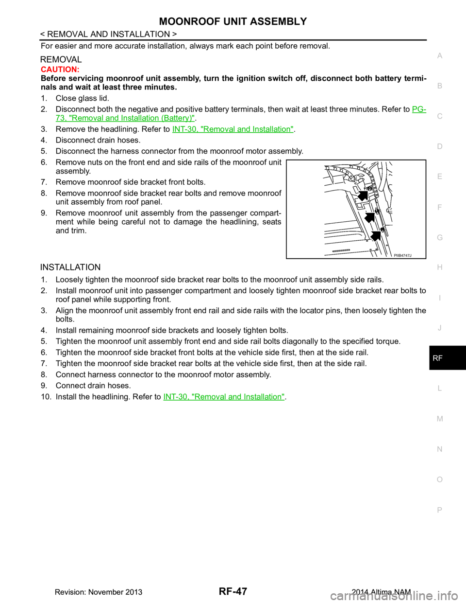
6. Remove nuts on the front end and side rails of the moonroof unit assembly.
7. Remove moonroof side bracket front bolts.
8. Remove moonroof side bracket rear bolts and remove moonroof unit assembly from roof panel.
9. Remove moonroof unit assembly from the passenger compart- ment while being careful not to damage the headlining, seats
and trim.
INSTALLATION
1. Loosely tighten the moonroof side bracket rear bolts to the moonroof unit assembly side rails.
2. Install moonroof unit into passenger compartment a nd loosely tighten moonroof side bracket rear bolts to
roof panel while supporting front.
3. Align the moonroof unit assembly front end rail and side rails with the locator pins, then loosely tighten the
bolts.
4. Install remaining moonroof side brackets and loosely tighten bolts.
5. Tighten the moonroof unit assembly front end and si de rail bolts diagonally to the specified torque.
6. Tighten the moonroof side bracket front bolts at the vehicle side first, then at the side rail.
7. Tighten the moonroof side bracket rear bolts at the vehicle side first, then at the side rail.
8. Connect harness connector to the moonroof motor assembly.
9. Connect drain hoses.
10. Install the headlining. Refer to INT-30, "Removal and Installation"
.
PIIB4747J
Revision: November 20132014 Altima NAMRevision: November 20132014 Altima NAM
Page 3722 of 4801
REAR SUSPENSION ASSEMBLYRSU-5
< PERIODIC MAINTENANCE >
C
D
F
G H
I
J
K L
M A
B
RSU
N
O P
PERIODIC MAINTENANCE
REAR SUSPENSION ASSEMBLY
On-vehicle ServiceINFOID:0000000009464454
• Check the suspension parts for excessive play, cracks, wear or damage. Shake each rear wheel to check for
excessive play.
• Retighten all nuts and bolts to the specified torque.
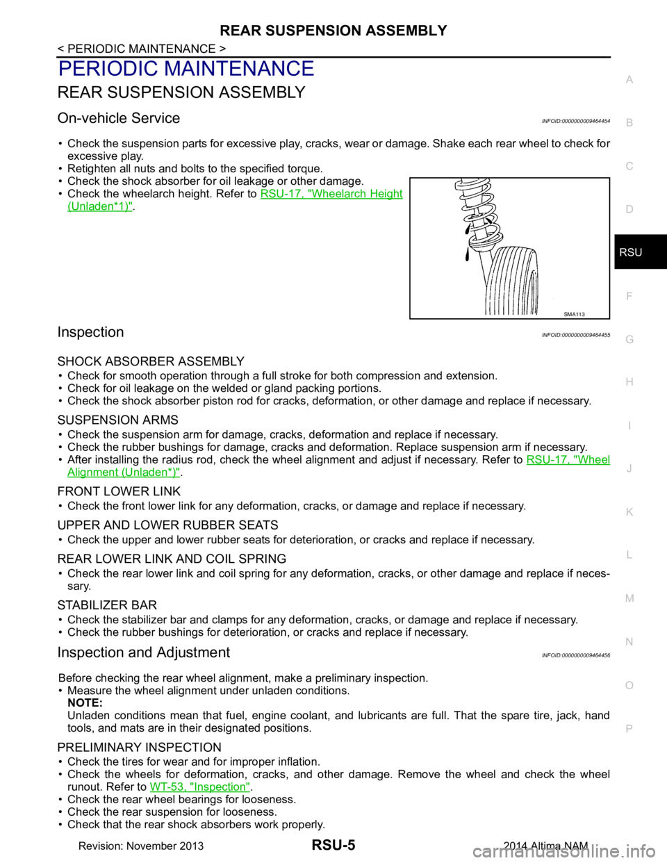
• Check the shock absorber for oil leakage or other damage.
• Check the wheelarch height. Refer to RSU-17, "Wheelarch Height
(Unladen*1)".
InspectionINFOID:0000000009464455
SHOCK ABSORBER ASSEMBLY
• Check for smooth operation through a full stroke for both compression and extension.
• Check for oil leakage on the welded or gland packing portions.
• Check the shock absorber piston r od for cracks, deformation, or other damage and replace if necessary.
SUSPENSION ARMS
• Check the suspension arm for damage, cracks, deformation and replace if necessary.
• Check the rubber bushings for damage, cracks and defo rmation. Replace suspension arm if necessary.
• After installing the radius rod, check the wheel alignment and adjust if necessary. Refer to RSU-17, "Wheel
Alignment (Unladen*)".
FRONT LOWER LINK
• Check the front lower link for any deformation, cracks, or damage and replace if necessary.
UPPER AND LOWER RUBBER SEATS
• Check the upper and lower rubber seats for deterioration, or cracks and replace if necessary.
REAR LOWER LINK AND COIL SPRING
• Check the rear lower link and coil spring for any def ormation, cracks, or other damage and replace if neces-
sary.
STABILIZER BAR
• Check the stabilizer bar and clamps for any deformation, cracks, or damage and replace if necessary.
• Check the rubber bushings for deterioration, or cracks and replace if necessary.
Inspection and AdjustmentINFOID:0000000009464456
Before checking the rear wheel ali gnment, make a preliminary inspection.
• Measure the wheel alignment under unladen conditions. NOTE:
Unladen conditions mean that fuel, engine coolant, and l ubricants are full. That the spare tire, jack, hand
tools, and mats are in their designated positions.
PRELIMINARY INSPECTION
• Check the tires for wear and for improper inflation.
• Check the wheels for deformation, cracks, and ot her damage. Remove the wheel and check the wheel
runout. Refer to WT-53, "Inspection"
.
• Check the rear wheel bearings for looseness.
• Check the rear suspension for looseness.
• Check that the rear shock absorbers work properly.
SMA113
Revision: November 20132014 Altima NAM
Page 3724 of 4801
REAR SUSPENSION ASSEMBLYRSU-7
< PERIODIC MAINTENANCE >
C
D
F
G H
I
J
K L
M A
B
RSU
N
O P
NOTE:
• Camber changes about 0 ° 5’ (0.08 °) with each graduation of the adjusting bolt.
• Turn the adjusting bolts in the same direction to calibrate camber.
• Toe changes about 1.5 mm (0.059 in) [one side] with each graduation of the adjusting bolt.
• Turn the adjusting bolts in the opposite direction to calibrate toe.
4. Tighten the adjusting bolt nuts to the specified torque. Camber : Refer to
RSU-17, "Wheel Alignment (Unlad-
en*)".
Total toe-in : Refer to RSU-17, "Wheel Alignment (Unlad-
en*)".
Adjusting bolt nuts : Refer to RSU-8, "Exploded View"
.
Revision: November 20132014 Altima NAM
Page 3726 of 4801
REAR SUSPENSION ASSEMBLYRSU-9
< UNIT REMOVAL AND INSTALLATION >
C
D
F
G H
I
J
K L
M A
B
RSU
N
O P
2. Remove the brake caliper torque member bolts, l eaving the brake hose attached. Reposition the brake
caliper aside with wire. Refer to BR-39, "BRAKE CALIPER ASSEMBLY : Exploded View"
.
CAUTION:
• Do not depress brake pedal while brake caliper assembly is removed.
• Do not twist or stretch the brake hose.
3. Put alignment marks on the disc brake rotor and rear hub and bearing assembly, then remove the disc brake rotor.
4. Disconnect parking brake cables from each knuckle. Refer to PB-9, "Exploded View"
.
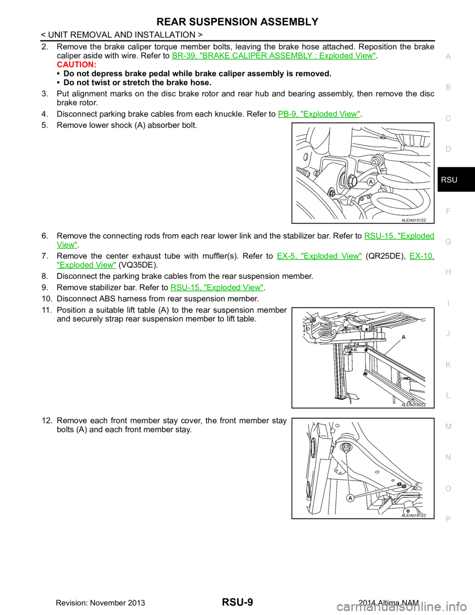
5. Remove lower shock (A) absorber bolt.
6. Remove the connecting rods from each rear lower link and the stabilizer bar. Refer to RSU-15, "Exploded
View".
7. Remove the center exhaust tube with muffler(s). Refer to EX-5, "Exploded View"
(QR25DE), EX-10,
"Exploded View" (VQ35DE).
8. Disconnect the parking brake cables from the rear suspension member.
9. Remove stabilizer bar. Refer to RSU-15, "Exploded View"
.
10. Disconnect ABS harness from rear suspension member.
11. Position a suitable lift table (A) to the rear suspension member and securely strap rear suspension member to lift table.
12. Remove each front member stay cover, the front member stay bolts (A) and each front member stay.
ALEIA0157ZZ
ALEIA0160ZZ
ALEIA0161ZZ
Revision: November 20132014 Altima NAM
Page 3731 of 4801
RSU-14
< REMOVAL AND INSTALLATION >
SHOCK ABSORBER
• Installation is the reverse order of removal.CAUTION:
Do not reuse non-reusable parts.
• Perform final tightening of shock absorber assembly lower side (rubber bushing) under unladen condition
with tires on level ground.
Disassembly and AssemblyINFOID:0000000009464462
DISASSEMBLY
CAUTION:
Do not damage piston rod when removi ng components from shock absorber.
1. Remove mounting seal from mounting bracket.
2. Wrap a shop cloth around lower side of shock absorber and secure it in a vise. CAUTION:
Do not set the cylindrical part of shock absorber in a vise.
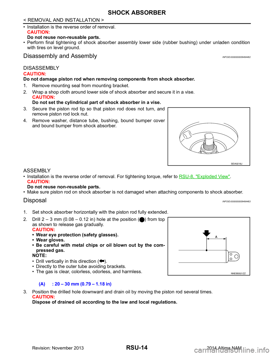
3. Secure the piston rod tip so that piston rod does not turn, and remove piston rod lock nut.
4. Remove washer, distance tube, bushing, bound bumper cover and bound bumper from shock absorber.
ASSEMBLY
• Installation is the reverse order of removal. For tightening torque, refer to RSU-8, "Exploded View".
CAUTION:
Do not reuse non-reusable parts.
• Make sure piston rod on shock absorber is not damaged when attaching components to shock absorber.
DisposalINFOID:0000000009464463
1. Set shock absorber horizontally with the piston rod fully extended.
2. Drill 2 – 3 mm (0.08 – 0.12 in) hole at the position ( ) from top as shown to release gas gradually.
CAUTION:
• Wear eye protection (safety glasses).
• Wear gloves.
• Be careful with metal chips or oil blown out by the com- pressed gas.
NOTE:
• Drill vertically in this direction ( ).
• Directly to the outer tube avoiding brackets.
• The gas is clear, colorless, odorless, and harmless.
3. Position the drilled hole downward and drain oil by moving the piston rod several times. CAUTION:
Dispose of drained oil according to the law and local regulations.
SEIA0218J
(A) : 20 – 30 mm (0.79 – 1.18 in)
NNEIB0021ZZ
Revision: November 20132014 Altima NAM
Page 3737 of 4801
SB-2
< PRECAUTION >
PRECAUTIONS
PRECAUTION
PRECAUTIONS
Precaution for Supplemental Restraint System (SRS) "AIR BAG" and "SEAT BELT
PRE-TENSIONER"
INFOID:0000000009951757
The Supplemental Restraint System such as “A IR BAG” and “SEAT BELT PRE-TENSIONER”, used along
with a front seat belt, helps to reduce the risk or severi ty of injury to the driver and front passenger for certain
types of collision. Information necessary to service the system safely is included in the SR and SB section of
this Service Manual.
WARNING:
• To avoid rendering the SRS inopera tive, which could increase the risk of personal injury or death in
the event of a collision which would result in air bag inflation, all maintenance must be performed by
an authorized NISS AN/INFINITI dealer.
• Improper maintenance, including in correct removal and installation of the SRS, can lead to personal
injury caused by unintent ional activation of the system. For re moval of Spiral Cable and Air Bag
Module, see the SR section.
• Do not use electrical test equipmen t on any circuit related to the SRS unless instructed to in this
Service Manual. SRS wiring harn esses can be identified by yellow and/or orange harnesses or har-
ness connectors.
PRECAUTIONS WHEN USING POWER TOOLS (AIR OR ELECTRIC) AND HAMMERS
WARNING:
• When working near the Airbag Diagnosis Sensor Unit or other Airbag System sensors with the Igni-
tion ON or engine running, DO NOT use air or electri c power tools or strike near the sensor(s) with a
hammer. Heavy vibration could activate the sensor( s) and deploy the air bag(s), possibly causing
serious injury.
• When using air or electric power tools or hammers , always switch the Ignition OFF, disconnect the
battery and wait at least three minutes before performing any service.
Precaution for Seat Belt ServiceINFOID:0000000009462957
CAUTION:
• Before removing the seat belt pre-tensioner assembl y, turn the ignition switch OFF, disconnect both
battery terminals and wait at least three minutes. For approximately three minutes after the battery
terminals have been removed, it is still possible for the air bag and seat belt pre-tensioner to deploy.
Therefore, do not attempt work on any SRS conn ectors or wires until at least three minutes have
passed.
• After replacing or reinstalling seat belt pre -tensioner assembly or reconnecting seat belt pre-ten-
sioner assembly connector, make sure entire SRS operates properly. Refer to SRC-15, "SRS Opera-
tion Check".
• Do not disassemble buckle or seat belt assembly.
• Replace anchor bolts if th ey are deformed or worn out.
• Do not oil tongue or buckle.
• If any component of seat belt assembly is questionable, do not re pair. Replace the whole seat belt
assembly.
• If webbing is cut, frayed or damaged, replace seat belt assembly.
• When replacing seat belt assembly, use a genuine NISSAN seat belt assembly.
Precaution for WorkINFOID:0000000009462958
• When removing or disassembling each component, be careful not to damage or deform it. If a component may be subject to interference, be sure to protect it with a shop cloth.
• When removing (disengaging) components with a screwdriver or similar tool, be sure to wrap the component with a shop cloth or vinyl tape to protect it.
• Protect the removed parts with a s hop cloth and prevent them from being dropped.
• Replace a deformed or damaged clip.
• If a part is specified as a non-reusable part, always replace it with a new one.
• Be sure to tighten bolts and nuts securely to the specified torque.
• After installation is complete, be sure to check that each part works properly.
Revision: November 20132014 Altima NAM