2014 NISSAN TEANA ESP
[x] Cancel search: ESPPage 2240 of 4801
![NISSAN TEANA 2014 Service Manual
EM-242
< UNIT DISASSEMBLY AND ASSEMBLY >[VQ35DE]
CYLINDER BLOCK
a. The grade number of each cylinder block main journal is
punched on the respective cylinder block. These numbers are
punched in eith NISSAN TEANA 2014 Service Manual
EM-242
< UNIT DISASSEMBLY AND ASSEMBLY >[VQ35DE]
CYLINDER BLOCK
a. The grade number of each cylinder block main journal is
punched on the respective cylinder block. These numbers are
punched in eith](/manual-img/5/57390/w960_57390-2239.png)
EM-242
< UNIT DISASSEMBLY AND ASSEMBLY >[VQ35DE]
CYLINDER BLOCK
a. The grade number of each cylinder block main journal is
punched on the respective cylinder block. These numbers are
punched in either Arabic or Roman numerals. If measured diam-
eter is out of the grade punched, decide suitable grade from
available main bearings.
b. The grade number of each crankshaft main journal is punched on the crankshaft end. These numbers are punched in either
Arabic or Roman numerals. If measured diameter is out of grade
punched, decide the suitable grade from available main bear-
ings.
c. Select the main bearing suitable thickness according to the following table:
SEM756G
SEM452G
PBIC0814E
Revision: November 20132014 Altima NAM
Page 2278 of 4801
EXL-12
< SYSTEM DESCRIPTION >
SYSTEM
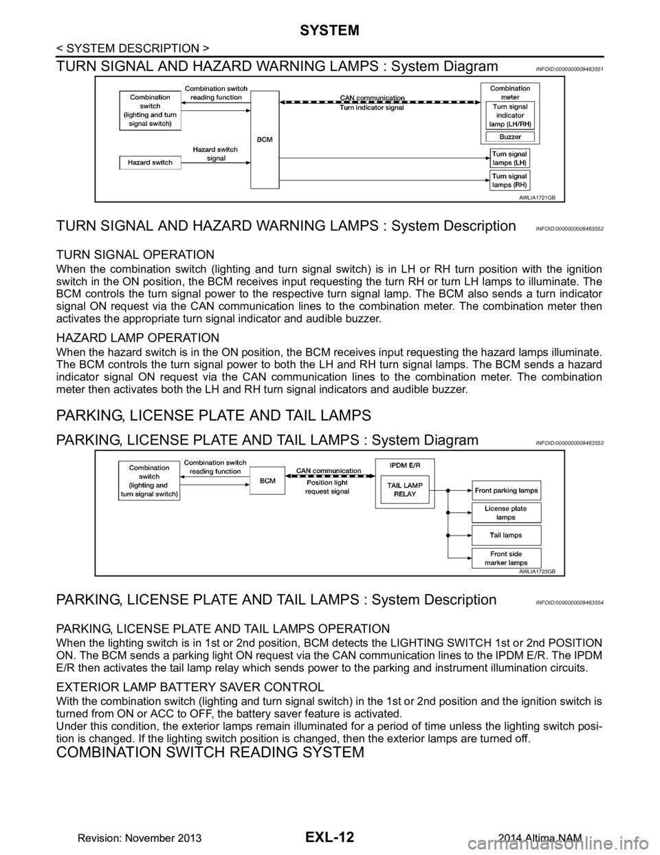
TURN SIGNAL AND HAZARD WARNI NG LAMPS : System Diagram
INFOID:0000000009463551
TURN SIGNAL AND HAZARD WARNING LAMPS : System DescriptionINFOID:0000000009463552
TURN SIGNAL OPERATION
When the combination switch (lighting and turn signal swit ch) is in LH or RH turn position with the ignition
switch in the ON position, the BCM receives input reques ting the turn RH or turn LH lamps to illuminate. The
BCM controls the turn signal power to the respective turn signal lamp. The BCM also sends a turn indicator
signal ON request via the CAN communication lines to the combination meter. The combination meter then
activates the appropriate turn signal indicator and audible buzzer.
HAZARD LAMP OPERATION
When the hazard switch is in the ON position, the BC M receives input requesting the hazard lamps illuminate.
The BCM controls the turn signal power to both the LH and RH turn signal lamps. The BCM sends a hazard
indicator signal ON request via the CAN communication lines to the combination meter. The combination
meter then activates both the LH and RH turn signal indicators and audible buzzer.
PARKING, LICENSE PLATE AND TAIL LAMPS
PARKING, LICENSE PLATE AND TAIL LAMPS : System DiagramINFOID:0000000009463553
PARKING, LICENSE PLATE AND TA IL LAMPS : System DescriptionINFOID:0000000009463554
PARKING, LICENSE PLATE AND TAIL LAMPS OPERATION
When the lighting switch is in 1st or 2nd position, BCM detects the LIGHTING SWITCH 1st or 2nd POSITION
ON. The BCM sends a parking light ON request via the CAN communication lines to the IPDM E/R. The IPDM
E/R then activates the tail lamp relay which sends power to the parking and instrument illumination circuits.
EXTERIOR LAMP BATTERY SAVER CONTROL
With the combination switch (lighting and turn signal switch) in the 1st or 2nd position and the ignition switch is
turned from ON or ACC to OFF, the battery saver feature is activated.
Under this condition, the exterior lamps remain illumi nated for a period of time unless the lighting switch posi-
tion is changed. If the lighting switch position is changed, then the exterior lamps are turned off.
COMBINATION SWITCH READING SYSTEM
AWLIA1721GB
AWLIA1723GB
Revision: November 20132014 Altima NAMRevision: November 20132014 Altima NAM
Page 2280 of 4801
EXL-14
< SYSTEM DESCRIPTION >
SYSTEM
Description
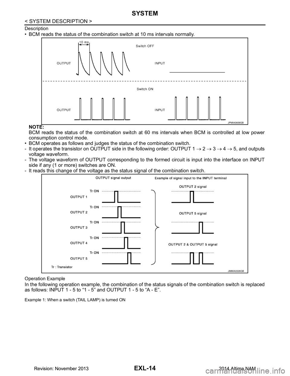
• BCM reads the status of the combination switch at 10 ms intervals normally.NOTE:
BCM reads the status of the combination switch at 60 ms intervals when BCM is controlled at low power
consumption control mode.
• BCM operates as follows and judges the status of the combination switch.
- It operates the transistor on OUTPUT side in the following order: OUTPUT 1 → 2 → 3 → 4 → 5, and outputs
voltage waveform.
- The voltage waveform of OUTPUT corresponding to the formed circuit is input into the interface on INPUT
side if any (1 or more) switches are ON.
- It reads this change of the voltage as the status signal of the combination switch.
Operation Example
In the following operation example, the combination of t he status signals of the combination switch is replaced
as follows: INPUT 1 - 5 to “1 - 5” and OUTPUT 1 - 5 to “A - E”.
Example 1: When a switch (TAIL LAMP) is turned ON
JPMIA0609GB
JMMIA0326GB
Revision: November 20132014 Altima NAMRevision: November 20132014 Altima NAM
Page 2424 of 4801
EXT-10
< PERIODIC MAINTENANCE >
SQUEAK AND RATTLE TROUBLE DIAGNOSES
PERIODIC MAINTENANCE
SQUEAK AND RATTLE TROUBLE DIAGNOSES
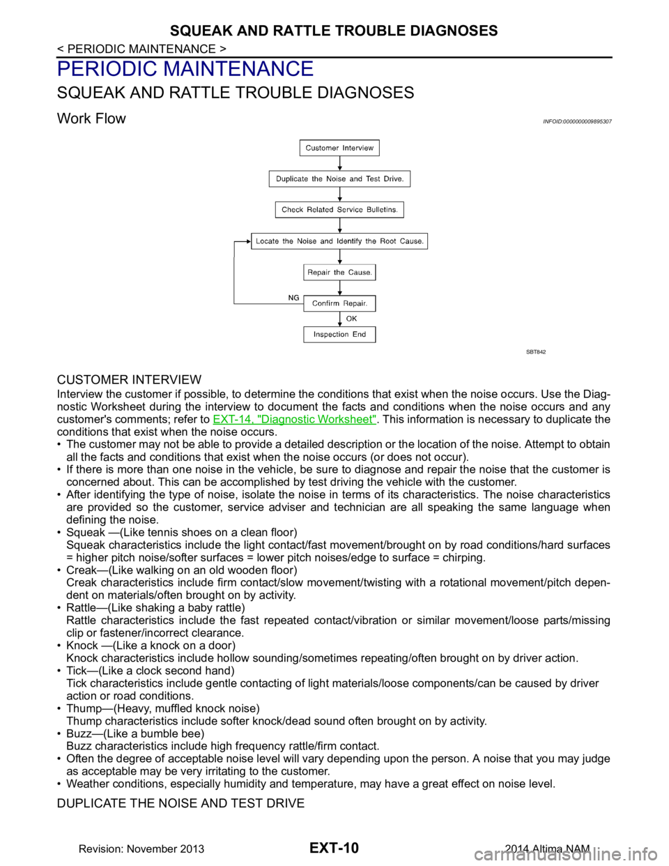
Work FlowINFOID:0000000009895307
CUSTOMER INTERVIEW
Interview the customer if possible, to determine the conditions that exist when the noise occurs. Use the Diag-
nostic Worksheet during the interview to document the facts and conditions when the noise occurs and any
customer's comments; refer to EXT-14, "Diagnostic Worksheet"
. This information is necessary to duplicate the
conditions that exist when the noise occurs.
• The customer may not be able to provide a detailed description or the location of the noise. Attempt to obtain
all the facts and conditions that exist w hen the noise occurs (or does not occur).
• If there is more than one noise in the vehicle, be sure to diagnose and repair the noise that the customer is
concerned about. This can be accomplished by test driving the vehicle with the customer.
• After identifying the type of noise, isolate the noise in terms of its characteristics. The noise characteristics
are provided so the customer, service adviser and technician are all speaking the same language when
defining the noise.
• Squeak —(Like tennis shoes on a clean floor) Squeak characteristics include the light contact/fast movement/brought on by road conditions/hard surfaces
= higher pitch noise/softer surfaces = lower pitch noises/edge to surface = chirping.
• Creak—(Like walking on an old wooden floor) Creak characteristics include firm contact/slow mo vement/twisting with a rotational movement/pitch depen-
dent on materials/often brought on by activity.
• Rattle—(Like shaking a baby rattle) Rattle characteristics include the fast repeated contac t/vibration or similar movement/loose parts/missing
clip or fastener/incorrect clearance.
• Knock —(Like a knock on a door) Knock characteristics include hollow sounding/someti mes repeating/often brought on by driver action.
• Tick—(Like a clock second hand) Tick characteristics include gentle contacting of light materials/loose components/can be caused by driver
action or road conditions.
• Thump—(Heavy, muffled knock noise)
Thump characteristics include softer k nock/dead sound often brought on by activity.
• Buzz—(Like a bumble bee) Buzz characteristics include hi gh frequency rattle/firm contact.
• Often the degree of acceptable noise level will vary depending upon the person. A noise that you may judge
as acceptable may be very irritating to the customer.
• Weather conditions, especially humidity and temperat ure, may have a great effect on noise level.
DUPLICATE THE NOISE AND TEST DRIVE
SBT842
Revision: November 20132014 Altima NAM
Page 2487 of 4801
FUEL LEVEL SENSOR UNIT, FUEL FILTER AND FUEL PUMP ASSEMBLYFL-7
< REMOVAL AND INSTALLATION >
C
D E
F
G H
I
J
K L
M A
FL
NP
O
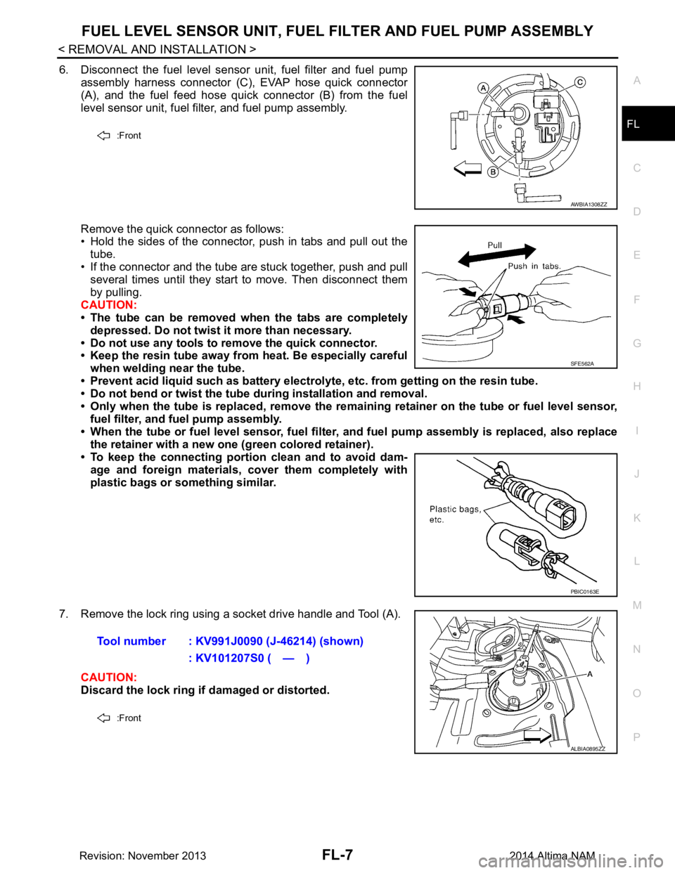
6. Disconnect the fuel level sensor unit, fuel filter and fuel pump
assembly harness connector (C), EVAP hose quick connector
(A), and the fuel feed hose quick connector (B) from the fuel
level sensor unit, fuel filter, and fuel pump assembly.
Remove the quick connector as follows:
• Hold the sides of the connector, push in tabs and pull out the
tube.
• If the connector and the tube are stuck together, push and pull several times until they start to move. Then disconnect them
by pulling.
CAUTION:
• The tube can be removed when the tabs are completely
depressed. Do not twist it more than necessary.
• Do not use any tools to remove the quick connector.
• Keep the resin tube away from heat. Be especially careful
when welding near the tube.
• Prevent acid liquid such as battery electroly te, etc. from getting on the resin tube.
• Do not bend or twist the tube during installation and removal.
• Only when the tube is replaced, remove the remaining retainer on the tube or fuel level sensor,
fuel filter, and fuel pump assembly.
• When the tube or fuel level sen sor, fuel filter, and fuel pump assembly is replaced, also replace
the retainer with a new one (green colored retainer).
• To keep the connecting portio n clean and to avoid dam-
age and foreign materials, cover them completely with
plastic bags or something similar.
7. Remove the lock ring using a socket drive handle and Tool (A). CAUTION:
Discard the lock ring if damaged or distorted.
:Front
AWBIA1308ZZ
SFE562A
PBIC0163E
Tool number : KV991J0090 (J-46214) (shown)
: KV101207S0 ( — )
:Front
ALBIA0895ZZ
Revision: November 20132014 Altima NAM
Page 2491 of 4801
FUEL TANKFL-11
< REMOVAL AND INSTALLATION >
C
D E
F
G H
I
J
K L
M A
FL
NP
O
• As a guide, if the fuel tank is full the fuel leve
l reaches or is less than the level on the fuel gauge as
shown, when approximately 34 (9 US gal, 7 1/2 Imp gal) of fuel is drained from a full fuel tank.
3. Open the fuel filler cap to release the pressure inside the fuel tank.
4. Release fuel pressure from fuel line. Refer to EC-182, "Work Procedure"
(QR25DE), EC-687, "Work Pro-
cedure" (VQ35DE).
5. Remove rear seat cushion. Refer to SE-36, "Removal and Installation - Seat Assembly"
.
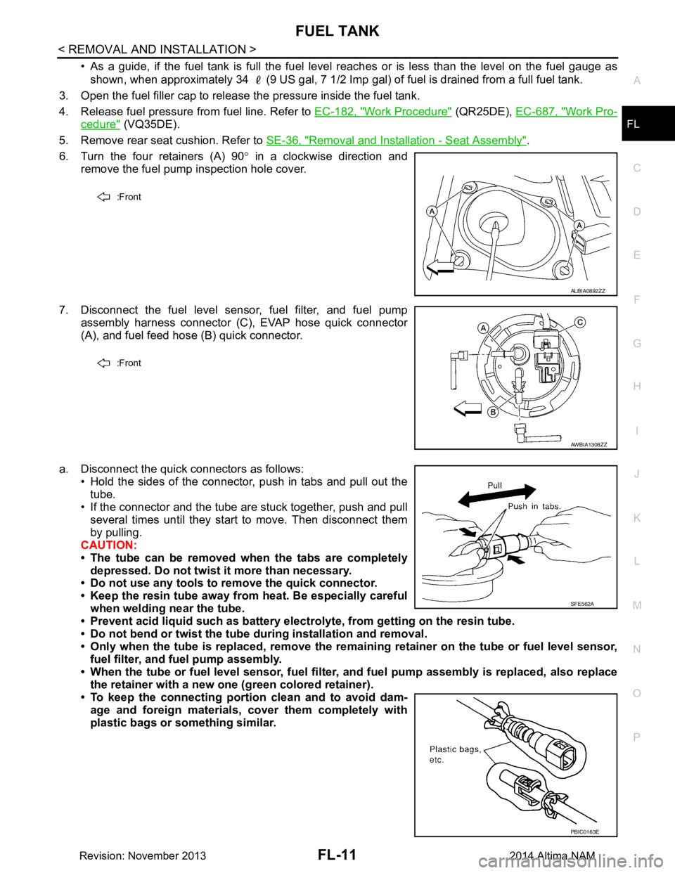
6. Turn the four retainers (A) 90 ° in a clockwise direction and
remove the fuel pump inspection hole cover.
7. Disconnect the fuel level sensor, fuel filter, and fuel pump assembly harness connector (C), EVAP hose quick connector
(A), and fuel feed hose (B) quick connector.
a. Disconnect the quick connectors as follows: • Hold the sides of the connector, push in tabs and pull out the
tube.
• If the connector and the tube are stuck together, push and pull
several times until they start to move. Then disconnect them
by pulling.
CAUTION:
• The tube can be removed when the tabs are completely depressed. Do not twist it more than necessary.
• Do not use any tools to remove the quick connector.
• Keep the resin tube away from heat. Be especially careful
when welding near the tube.
• Prevent acid liquid such as battery elect rolyte, from getting on the resin tube.
• Do not bend or twist the tube during installation and removal.
• Only when the tube is replaced, remove the remaining retainer on the tube or fuel level sensor,
fuel filter, and fuel pump assembly.
• When the tube or fuel level sen sor, fuel filter, and fuel pump assembly is replaced, also replace
the retainer with a new one (green colored retainer).
• To keep the connecting portio n clean and to avoid dam-
age and foreign materials, cover them completely with
plastic bags or something similar.
:Front
ALBIA0892ZZ
:Front
AWBIA1308ZZ
SFE562A
PBIC0163E
Revision: November 20132014 Altima NAM
Page 2526 of 4801
SERVICE DATA AND SPECIFICATIONS (SDS)FSU-25
< SERVICE DATA AND SPECIFICATIONS (SDS)
C
D
F
G H
I
J
K L
M A
B
FSU
N
O P
SERVICE DATA AND SPECIFICATIONS (SDS)
SERVICE DATA AND SPECIFICATIONS (SDS)
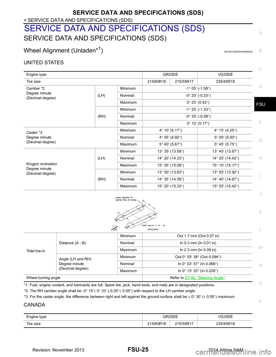
Wheel Alignment (Unladen*1)INFOID:0000000009460639
UNITED STATES
*1: Fuel, engine coolant, and lubricants are full. Spare tire, jack, hand tools, and mats are in designated positions.
*2: The RH camber angle shall be -0 ° 15 ′± 0 ° 33 ′ (-0.25 °± 0.55 °) with respect to the LH camber angle.
*3: For the caster angle, the difference between right and left against the ground surface shall be ± 0 ° 30 ′ ( ± 0.50 °) maximum.
CANADA
Engine type QR25DE VQ35DE
Tire size 215/60R16 215/55R17 235/45R18
Camber *2
Degree minute
(Decimal degree) (LH)Minimum -1
° 05 ′ (-1.08 °)
Nominal -0 ° 20 ′ (-0.33 °)
Maximum 0 ° 25 ′ (0.42 °)
(RH) Minimum -1
° 20 ′ (-1.33 °)
Nominal -0 ° 35 ′ (-0.58 °)
Maximum 0 ° 10 ′ (0.17 °)
Caster *3
Degree minute
(Decimal degree) Minimum 4
° 10 ′ (4.17 °)4 ° 15 ′ (4.25 °)
Nominal 4 ° 55 ′ (4.92 °)5 ° 00 ′ (5.00 °)
Maximum 5 ° 40 ′ (5.67 °)5 ° 45 ′ (5.75 °)
Kingpin inclination
Degree minute
(Decimal degree) (LH)
Minimum 13
° 35 ′ (13.58 °)13 ° 40
′ (13.67 °)
Nominal 14 ° 20 ′ (14.33 °)14 ° 25 ′ (14.42 °)
Maximum 15 ° 05 ′ (15.08 °)15 ° 10 ′ (15.17 °)
(RH) Minimum 13
° 50 ′ (13.83 °)13 ° 55 ′ (13.92 °)
Nominal 14 ° 35 ′ (14.58 °)14 ° 40 ′ (14.67 °)
Maximum 15 ° 20 ′ (15.33 °)15 ° 25 ′ (15.42 °)
To t a l t o e - i n Distance (A - B)
Minimum Out 1.7 mm (Out 0.07 in)
Nominal In 0.3 mm (In 0.01 in)
Maximum In 2.3 mm (In 0.09 in)
Angle (LH and RH)
Degree minute
(Decimal degree) Minimum Out 0
° 05 ′ 38 ″ (Out 0.094 °)
Nominal In 0 ° 03 ′ 57 ″ (In 0.066 °)
Maximum In 0 ° 13 ′ 33 ″ (In 0.226 °)
Wheel turning angle Refer to ST-46, "Steering Angle"
.
SFA234AC
Engine type QR25DE VQ35DE
Tire size 215/60R16 215/55R17 235/45R18
Revision: November 20132014 Altima NAM
Page 2527 of 4801
FSU-26
< SERVICE DATA AND SPECIFICATIONS (SDS)
SERVICE DATA AND SPECIFICATIONS (SDS)
*1: Fuel, engine coolant, and lubricants are full. Spare tire, jack, hand tools, and mats are in designated positions.
*2: The RH camber angle shall be -0 ° 15 ′± 0 ° 33 ′ (-0.25 °± 0.55 °) with respect to the LH camber angle.
*3: For the caster angle, the difference between right and left against the ground surface shall be ± 0 ° 30 ′ ( ± 0.50 °) maximum.
Ball JointINFOID:0000000009460640
Wheelarch Height (Unladen*1)INFOID:0000000009460641
UNITED STATES
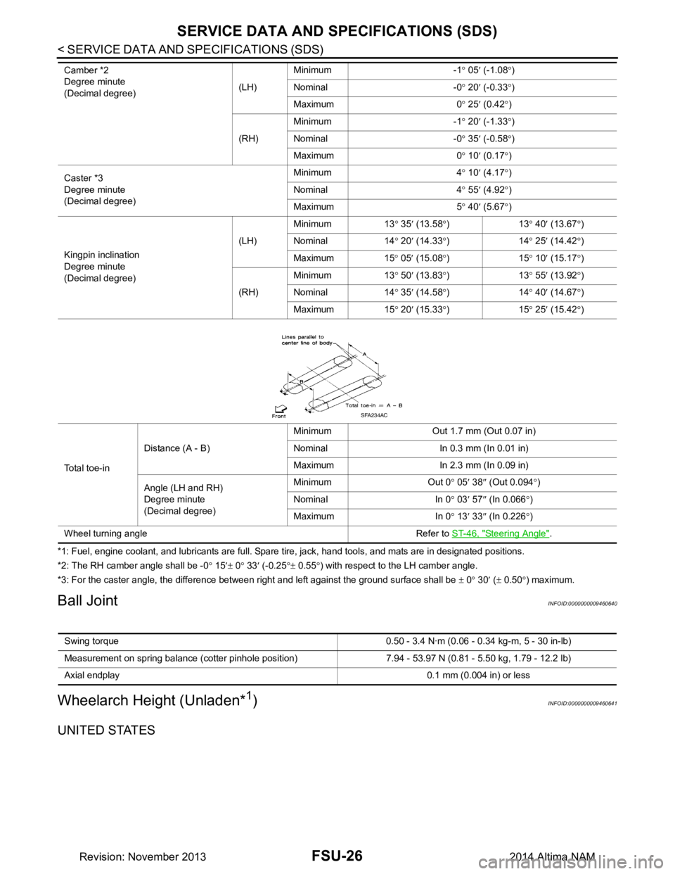
Camber *2
Degree minute
(Decimal degree) (LH)Minimum -1
° 05 ′ (-1.08 °)
Nominal -0 ° 20 ′ (-0.33 °)
Maximum 0 ° 25 ′ (0.42 °)
(RH) Minimum -1
° 20 ′ (-1.33 °)
Nominal -0 ° 35 ′ (-0.58 °)
Maximum 0 ° 10 ′ (0.17 °)
Caster *3
Degree minute
(Decimal degree) Minimum 4
° 10 ′ (4.17 °)
Nominal 4 ° 55 ′ (4.92 °)
Maximum 5 ° 40 ′ (5.67 °)
Kingpin inclination
Degree minute
(Decimal degree) (LH)
Minimum 13
° 35 ′ (13.58 °)13 ° 40 ′ (13.67 °)
Nominal 14 ° 20 ′ (14.33 °)14 ° 25 ′ (14.42 °)
Maximum 15 ° 05 ′ (15.08 °)15 ° 10 ′ (15.17 °)
(RH) Minimum 13
° 50 ′ (13.83 °)13 ° 55 ′ (13.92 °)
Nominal 14 ° 35 ′ (14.58 °)14 ° 40 ′ (14.67 °)
Maximum 15 ° 20 ′ (15.33 °)15 ° 25 ′ (15.42 °)
Total toe-in Distance (A - B)
Minimum Out 1.7 mm (Out 0.07 in)
Nominal In 0.3 mm (In 0.01 in)
Maximum In 2.3 mm (In 0.09 in)
Angle (LH and RH)
Degree minute
(Decimal degree) Minimum Out 0
° 05 ′ 38 ″ (Out 0.094 °)
Nominal In 0 ° 03 ′ 57 ″ (In 0.066 °)
Maximum In 0 ° 13 ′ 33 ″ (In 0.226 °)
Wheel turning angle Refer to ST-46, "Steering Angle"
.
SFA234AC
Swing torque 0.50 - 3.4 N·m (0 .06 - 0.34 kg-m, 5 - 30 in-lb)
Measurement on spring balance (cotter pinhole position) 7.94 - 53.97 N (0.81 - 5.50 kg, 1.79 - 12.2 lb)
Axial endplay 0.1 mm (0.004 in) or less
Revision: November 20132014 Altima NAM