2014 NISSAN TEANA sensor
[x] Cancel search: sensorPage 3388 of 4801
![NISSAN TEANA 2014 Service Manual
PCS
DIAGNOSIS SYSTEM (BCM)PCS-39
< SYSTEM DESCRIPTION > [POWER DISTRIBUTION SYSTEM]
C
D E
F
G H
I
J
K L
B
A
O P
N
INTELLIGENT KEY
INTELLIGENT KEY : CONSULT Func
tion (BCM - INTELLIGENT KEY)INFOID:0 NISSAN TEANA 2014 Service Manual
PCS
DIAGNOSIS SYSTEM (BCM)PCS-39
< SYSTEM DESCRIPTION > [POWER DISTRIBUTION SYSTEM]
C
D E
F
G H
I
J
K L
B
A
O P
N
INTELLIGENT KEY
INTELLIGENT KEY : CONSULT Func
tion (BCM - INTELLIGENT KEY)INFOID:0](/manual-img/5/57390/w960_57390-3387.png)
PCS
DIAGNOSIS SYSTEM (BCM)PCS-39
< SYSTEM DESCRIPTION > [POWER DISTRIBUTION SYSTEM]
C
D E
F
G H
I
J
K L
B
A
O P
N
INTELLIGENT KEY
INTELLIGENT KEY : CONSULT Func
tion (BCM - INTELLIGENT KEY)INFOID:0000000009941331
CAUTION:
After disconnecting the CONSULT vehicle interface (VI) from the data link connector, the ignition must
be cycled OFF → ON (for at least 5 seconds) → OFF. If this step is not performed, the BCM may not go
to ”sleep mode”, potentiall y causing a discharged battery and a no-start condition.
SELF DIAGNOSTIC RESULT
Refer to BCS-52, "DTC Index".
DATA MONITOR
RAP system RETAINED PWR ×
Signal buffer system SIGNAL BUFFER ×
TPMS AIR PRESSURE MONITOR ××××
System Sub System
Direct Diagnostic Mode
Ecu Identification
Self Diagnostic Result
Data Monitor
Active Test
Work support
Configuration
CAN Diag Support Mntr
Monitor Item [Unit] Main Description
REQ SW -DR [On/Off] ×Indicates condition of door request switch LH.
REQ SW -AS [On/Off] ×Indicates condition of door request switch RH.
REQ SW -BD/TR [On/Off] ×Indicates condition of trunk opener request switch.
PUSH SW [On/Off] Indicates condition of push-button ignition switch.
SHFTLCK SLNID PER SPLY [On/Off] ×Indicates condition of power supply to shiftlock solenoid.
BRAKE SW 1 [On/Off] ×Indicates condition of brake switch.
BRAKE SW 2 [On/Off] Indicates condition of brake switch.
DETE/CANCL SW [On/Off] ×Indicates condition of P (park) position.
SFT PN/N SW [On/Off] ×Indicates condition of P (park) or N (neutral) position.
UNLK SEN -DR [On/Off] ×Indicates condition of door unlock sensor.
PUSH SW -IPDM [On/Off] Indicates condition of push-button ignition switch received from IPDM E/R
on CAN communication line.
IGN RLY1 -F/B [On/Off] Indicates condition of ignition relay 1 received from IPDM E/R on CAN
communication line.
DETE SW -IPDM [On/Off] Indicates condition of detent switch received from TCM on CAN communi-
cation line.
SFT PN -IPDM [On/Off] Indicates condition of P (park) or N (neutral) position from TCM on CAN
communication line.
SFT P -MET [On/Off] Indicates condition of P (park) position from TCM on CAN communication
line.
SFT N -MET [On/Off] Indicates condition of N (neutral) position from IPDM E/R on CAN commu-
nication line.
ENGINE STATE [STOP/START/CRANK/RUN] ×Indicates condition of engine state from ECM on CAN communication line.
VEH SPEED 1 [mph/km/h] ×Indicates condition of vehicle speed signal received from ABS on CAN
communication line.
Revision: November 20132014 Altima NAMRevision: November 20132014 Altima NAM
Page 3403 of 4801
![NISSAN TEANA 2014 Service Manual
PCS-54
< BASIC INSPECTION >[POWER DISTRIBUTION SYSTEM]
DIAGNOSIS AND REPAIR WORKFLOW
1.GET INFORMATION FOR SYMPTOM
1. Get detailed information from the customer about the symptom (the condition and NISSAN TEANA 2014 Service Manual
PCS-54
< BASIC INSPECTION >[POWER DISTRIBUTION SYSTEM]
DIAGNOSIS AND REPAIR WORKFLOW
1.GET INFORMATION FOR SYMPTOM
1. Get detailed information from the customer about the symptom (the condition and](/manual-img/5/57390/w960_57390-3402.png)
PCS-54
< BASIC INSPECTION >[POWER DISTRIBUTION SYSTEM]
DIAGNOSIS AND REPAIR WORKFLOW
1.GET INFORMATION FOR SYMPTOM
1. Get detailed information from the customer about the symptom (the condition and the environment when
the incident/malfunction occurs).
2. Check operation condition of the com ponent or system that is malfunctioning.
>> GO TO 2.
2.CHECK DTC
1. Check DTC.
2. Perform the following procedure if DTC is detected.
- Record DTC and freeze frame data (P rint them out using CONSULT).
- Erase DTC.
- Study the relationship between the cause detected by DTC and the symptom described by the customer.
3. Check related service bulletins for information.
Are any symptoms described and any DTC detected?
Symptom is described, DTC is detected>>GO TO 3.
Symptom is described, DTC is not detected>>GO TO 4.
Symptom is not described, DTC is detected>>GO TO 5.
3.CONFIRM THE SYMPTOM
Try to confirm the symptom described by the customer.
Also study the normal operation and fail-safe related to the symptom.
Verify relation between the symptom and the condition when the symptom is detected.
>> GO TO 5.
4.CONFIRM THE SYMPTOM
Try to confirm the symptom described by the customer.
Verify relation between the symptom and the condition when the symptom is detected.
NOTE:
Freeze frame data is useful if the DTC is not detected.
>> GO TO 6.
5.PERFORM DTC CONFIRMATION PROCEDURE
Perform DTC CONFIRMATION PROCEDURE for the det ected DTC, and then check that DTC is detected
again. At this time, always connect CONSULT to the v ehicle, and check self diagnostic results in real time.
If two or more DTCs are detected, refer to BCS-50, "DTC Inspection Priority Chart"
, and determine trouble
diagnosis order.
Is DTC detected?
YES >> GO TO 7.
NO >> Refer to GI-43, "Intermittent Incident"
.
6.DETECT MALFUNCTIONING SYSTEM BY SYMPTOM DIAGNOSIS
Detect malfunctioning system according to SYMPTOM DIAGNOSIS based on the confirmed symptom in step
4, and determine the trouble diagnosis order based on possible causes and symptom.
Is the symptom described?
YES >> GO TO 7.
NO >> Monitor input data from related sensors or check voltage of related module terminals using CON- SULT.
7.DETECT MALFUNCTIONING PART BY DIAGNOSIS PROCEDURE
Inspect according to Diagnos is Procedure of the system.
Is malfunctioning part detected?
YES >> GO TO 8.
NO >> Refer to GI-43, "Intermittent Incident"
.
Revision: November 20132014 Altima NAMRevision: November 20132014 Altima NAM
Page 3434 of 4801

PG-2
< PRECAUTION >
PRECAUTIONS
PRECAUTION
PRECAUTIONS
Precaution for Supplemental Restraint System (SRS) "AIR BAG" and "SEAT BELT
PRE-TENSIONER"
INFOID:0000000009951599
The Supplemental Restraint System such as “A IR BAG” and “SEAT BELT PRE-TENSIONER”, used along
with a front seat belt, helps to reduce the risk or severi ty of injury to the driver and front passenger for certain
types of collision. Information necessary to service the system safely is included in the SR and SB section of
this Service Manual.
WARNING:
• To avoid rendering the SRS inopera tive, which could increase the risk of personal injury or death in
the event of a collision which would result in air bag inflation, all maintenance must be performed by
an authorized NISS AN/INFINITI dealer.
• Improper maintenance, including in correct removal and installation of the SRS, can lead to personal
injury caused by unintent ional activation of the system. For re moval of Spiral Cable and Air Bag
Module, see the SR section.
• Do not use electrical test equipmen t on any circuit related to the SRS unless instructed to in this
Service Manual. SRS wiring harn esses can be identified by yellow and/or orange harnesses or har-
ness connectors.
PRECAUTIONS WHEN USING POWER TOOLS (AIR OR ELECTRIC) AND HAMMERS
WARNING:
• When working near the Airbag Diagnosis Sensor Unit or other Airbag System sensors with the Igni-
tion ON or engine running, DO NOT use air or electri c power tools or strike near the sensor(s) with a
hammer. Heavy vibration could activate the sensor( s) and deploy the air bag(s), possibly causing
serious injury.
• When using air or electric power tools or hammers , always switch the Ignition OFF, disconnect the
battery and wait at least three minutes before performing any service.
Revision: November 20132014 Altima NAM
Page 3471 of 4801

PG
HARNESSPG-39
< DTC/CIRCUIT DIAGNOSIS >
C
D E
F
G H
I
J
K L
B
A
O P
N
HARNESS
Harness LayoutINFOID:0000000009995712
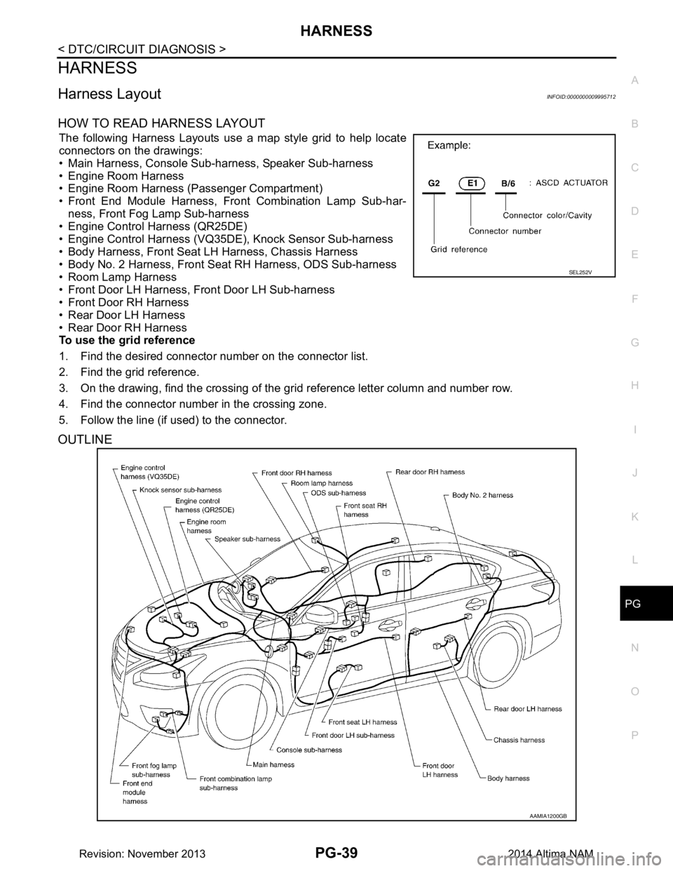
HOW TO READ HARNESS LAYOUT
The following Harness Layouts use a map style grid to help locate
connectors on the drawings:
• Main Harness, Console Sub-harness, Speaker Sub-harness
• Engine Room Harness
• Engine Room Harness (Passenger Compartment)
• Front End Module Harness, Fr ont Combination Lamp Sub-har-
ness, Front Fog Lamp Sub-harness
• Engine Control Harness (QR25DE)
• Engine Control Harness (VQ35DE), Knock Sensor Sub-harness
• Body Harness, Front Seat LH Harness, Chassis Harness
• Body No. 2 Harness, Front Seat RH Harness, ODS Sub-harness
• Room Lamp Harness
• Front Door LH Harness, Front Door LH Sub-harness
• Front Door RH Harness
• Rear Door LH Harness
• Rear Door RH Harness
To use the grid reference
1. Find the desired connector number on the connector list.
2. Find the grid reference.
3. On the drawing, find the crossing of the grid reference letter column and number row.
4. Find the connector number in the crossing zone.
5. Follow the line (if used) to the connector.
OUTLINE
SEL252V
AAMIA1200GB
Revision: November 20132014 Altima NAM
Page 3472 of 4801

PG-40
< DTC/CIRCUIT DIAGNOSIS >
HARNESS
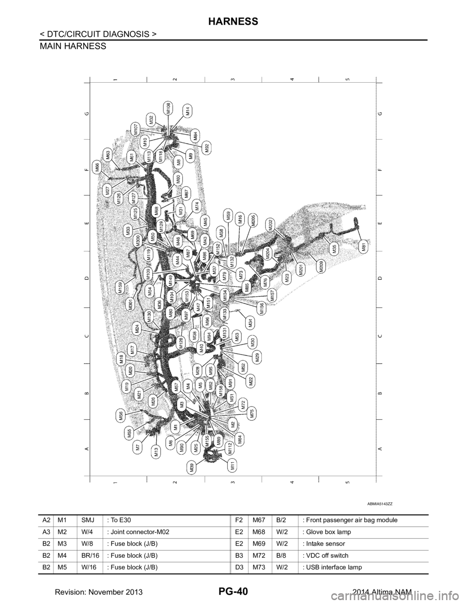
MAIN HARNESS
ABMIA5143ZZ
A2 M1 SMJ : To E30 F2 M67 B/2 : Front passenger air bag module
A3 M2 W/4 : Joint connector-M02 E2 M68 W/2 : Glove box lamp
B2 M3 W/8 : Fuse block (J/B) E2 M69 W/2 : Intake sensor
B2 M4 BR/16 : Fuse block (J/B) B3 M72 B/8 : VDC off switch
B2 M5 W/16 : Fuse block (J/B) D3 M73 W/2 : USB interface lamp
Revision: November 20132014 Altima NAM
Page 3473 of 4801

PG
HARNESSPG-41
< DTC/CIRCUIT DIAGNOSIS >
C
D E
F
G H
I
J
K L
B
A
O P
N
A2 M6 SMJ : To B1 E2 M74 W/2 : Trunk lid opener cancel switch
A1 M7 W/12 : To R1 B3 M75 G/8 : Trunk lid opener switch
F2 M8 W/12 : To B102 D4 M76 GR/3 : Front power socket
F2 M9 W/16 : To B103 D3 M79 W/12 : A/C switch assembly
F 1 M 1 0 B R / 1 6 : T o B 1 0 4 C 2 M 8 0 B / 2 : D i o d e - 3
A3 M11 W/16 : To D1 E5 M81 GR/2 : Front console antenna
A 2 M 1 3 W / 4 : T o R 2 G 2 M 8 4 W / 2 4 : T o D 1 1 4
G2 M14 W/8 : To D101 D3 M85 W/20 : Audio unit (With base audio system)
E3 M16 W/16 : To M205 D2 M86 W/16 : Audio unit (With base audio system)
C1 M17 G/40 : BCM (Body control module) D2 M87 W/8 : Audio unit (With base audio system)
C1 M18 B/40 : BCM (Body control module) A3 M89 W/4 : Joint connector-M05
B1 M19 GR/24 : BCM (Body control module) A2 M90 L/4 : Heated steering relay
B1 M20 B/24 : BCM (Body control module) B3 M91 W/12 : Accessory prewire LH
B1 M21 W/15 : BCM (Body control module) F2 M92 W/12 : Accessory prewire RH
B3 M22 W/16 : Data link connector C3 M94 W/4 : Paddle shifter (Shift up)
D4 M23 W/12 : CVT shift selector B3 M95 W/3 : Paddle shifter (Shift down)
C1 M24 W/40 : Combination meter C3 M96 W/20 : AV control unit (With navigation system
without BOSE audio system)
A2 M25 B/4 : Accessory relay-2 C2 M97 W/24 : AV control unit (With navigation system
without BOSE audio system)
B2 M26 W/12 : Combination meter D2 M104 W/4 : Aux in jack
F1 M27 B/4 : Remote keyless entry receiver G1 M107 W/4 : Joint connector-M10
C2 M28 W/16 : Combination switch G2 M108 W/4 : Joint connector-M11
C3 M29 Y/6 : Combination switch (Spiral cable) D2 M109 W/8 : Audio unit (With display audio system
without BOSE audio system)
C3 M30 GR/8 : Combination switch (Spiral cable) A3 M112 W/24 : To D2
E2 M31 W/6 : Blower motor F2 M113 W/4 : Joint connector-M12
G2 M32 Y/4 : To D123 F2 M118 W/4 : Joint connector-M13
E1 M33 W/3 : To M125 D2 M119 W/8 : Audio unit (With display audio system
and BOSE audio system)
C3 M34 W/2 : In-vehicle sensor E1 M125 W/3 : To M33
E5 M35 Y/28 : Air bag diagnosis sensor unit E1 M126 W/3 : Intake door motor
D2 M36 BR/2 : Front passenger air bag off indicator E1 M127 W/3 : Mode door motor
D3 M37 W/16 : Front air control (Without auto A/C) C2 M128 W/3 : Air mix door motor LH
C2 M38 W/8 : Push-button ignition switch E2 M129 W/3 : Air mix door motor RH
A2 M39 Y/4 : To D29 C2 M130 W/3 : Air mix door motor
C2 M40 W/3 : NATS antenna amp. C3 M131 L/5 : AV control unit (With navigation with
BOSE audio system)
E 2 M 4 3 W / 2 0 : Audio unit (With display audio system
without BOSE audio system) D3 M132
L/5 : USB interface
D 2 M 4 4 W / 3 2 : Audio unit (With display audio system
without BOSE audio system) C3 M133 L/5
: Audio unit (With display audio system
without BOSE audio system)
E 3 M 4 5 W / 2 0 : Audio unit (With display audio system
and BOSE audio system) D3 M134
L/5 : AV control unit (With navigation system
without BOSE audio system)
E 2 M 4 6 W / 3 2 : Audio unit (With display audio system
and BOSE audio system) D2 M149
L/5 : Audio unit (With display audio system
and BOSE audio system)
D2 M47 W/4 : Joint connector-M04 D3 M151 W/20 : AV control unit (With navigation system
with BOSE audio system)
E2 M50 W/2 : To M300 E3 M152 W/40 : A/C auto amp.(With auto A/C)
Revision: November 20132014 Altima NAM
Page 3474 of 4801

PG-42
< DTC/CIRCUIT DIAGNOSIS >
HARNESS
B3 M51 L/8 : Heated steering wheel switch D2 M153 W / 2 4: AV control unit (With navigation system
with BOSE audio system)
C3 M52 W/2 : Combination switch (Spiral cable) A3 M155 W/4 : Joint connector-M06
C3 M53 W/8 : Steering angle sensor C3 M156 W/4 : Joint connector-M07
D2 M54 W/4 : Hazard switch D3 M157 W/4 : Joint connector-M08
A1 M55 BR/2 : Front speaker LH B3 M158 W/8 : Meter control switch
B1 M56 B/2 : Sunload sensor D1 M159 W/4 : Dongle unit
B2 M57 — : Body ground Console sub-harness
E3 M58 W/40 : ITS control unit D4 M201 W/6 : Front heated seat switch LH
E3 M59 W/32 : ITS control unit E4 M202 BR/6 : Front heated seat switch RH
F2 M60 O/2 : Front passenger air bag module D4 M204 BR/2 : CVT shift selector
F1 M61 — : Body ground E3 M205 W / 1 6 : T o M 1 6
B3 M62 GR/8 : Warning system switch D5 M209 GR/3 : Front console power socket
F1 M63 BR/2 : Front speaker RH Speaker sub-harness
A3 M64 W/4 : Joint connector-M01 D1 M300 W / 2 : T o M 5 0
F1 M66 W/3 : Optical sensor D1 M301 BR/2 : Center speaker
Revision: November 20132014 Altima NAM
Page 3475 of 4801

PG
HARNESSPG-43
< DTC/CIRCUIT DIAGNOSIS >
C
D E
F
G H
I
J
K L
B
A
O P
N
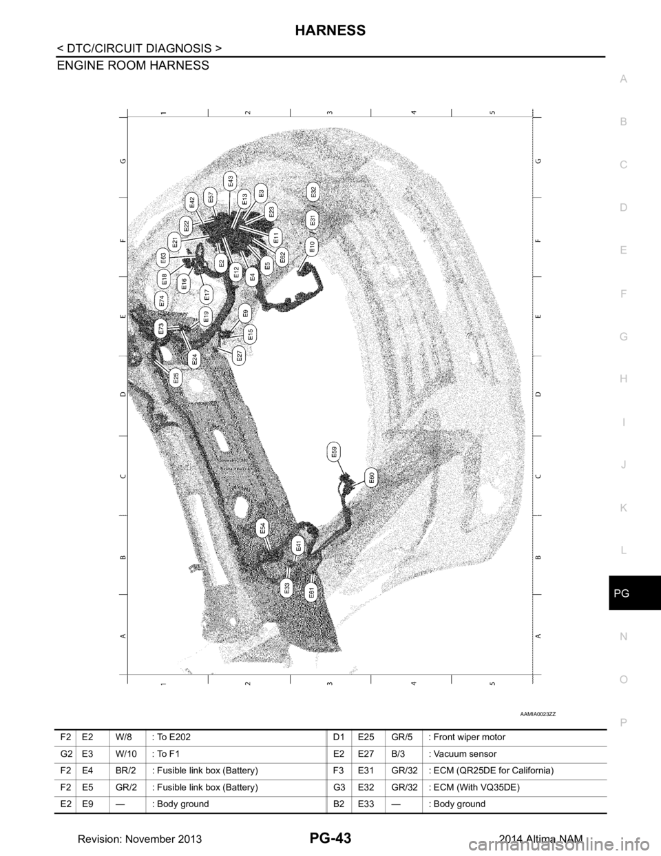
ENGINE ROOM HARNESS
AAMIA0023ZZ
F2 E2 W/8 : To E202 D1 E25 GR/5 : Front wiper motor
G2 E3 W/10 : To F1 E2 E27 B/3 : Vacuum sensor
F 2 E 4 B R / 2 : F u s i b l e l i n k b o x ( B a t t e r y ) F 3 E 31 GR/32 : ECM (QR25DE for California)
F2 E5 GR/2 : Fusible link box (Battery) G3 E32 GR/32 : ECM (With VQ35DE)
E2 E9 — : Body ground B2 E33 — : Body ground
Revision: November 20132014 Altima NAM