2014 NISSAN TEANA sensor
[x] Cancel search: sensorPage 4714 of 4801

C1724, C1725, C1726, C1727 TRANSMI TTER (BATT VOLT)
WT-39
< DTC/CIRCUIT DIAGNOSIS >
C
D
F
G H
I
J
K L
M A
B
WT
N
O P
C1724, C1725, C1726, C1727 TR ANSMITTER (BATT VOLT)
DTC LogicINFOID:0000000009464504
NOTE:
The Signal Tech II Tool (J-50190) can be used to perform the following functions. Refer to the Signal Tech II
User Guide for additional information.
• Activate and display TPMS transmitter IDs
• Display tire pressure repor ted by the TPMS transmitter
• Read TPMS DTCs
• Register TPMS transmitter IDs
DTC DETECTION LOGIC
DTC CONFIRMATION PROCEDURE
1.PERFORM SELF DIAGNOSTIC RESULT
With CONSULT
1. Drive at a speed of 40 km/h (25 MPH) or more fo r 3 minutes, and then drive the vehicle at any speed for
10 minutes.
2. Perform Self Diagnostic Result.
Is DTC C1724, C1725, C1726, or C1727 detected?
YES >> Proceed to WT-39, "Diagnosis Procedure".
NO >> Inspection End.
Diagnosis ProcedureINFOID:0000000009464505
NOTE:
The Signal Tech II Tool (J-50190) can be used to perform the following functions. Refer to the Signal Tech II
User Guide for additional information.
• Activate and display TPMS transmitter IDs
• Display tire pressure repor ted by the TPMS transmitter
• Read TPMS DTCs
• Register TPMS transmitter IDs
1.TIRE PRESSURE SENS OR ID REGISTRATION
Perform tire pressure sensor ID registration. Refer to WT-25, "Work Procedure"
.
Can the tire pressure sensor ID registration be completed?
YES >> GO TO 2.
NO >> Replace applicable tire pressure sensor. Refer to WT-57, "Removal and Installation"
.
2.PERFORM SELF DIAGNOSTIC RESULT
With CONSULT
1. Drive at a speed of 40 km/h (25 MPH) or more fo r 3 minutes, and then drive the vehicle at any speed for
10 minutes.
2. Perform Self Diagnostic Result.
Is DTC C1724, C1725, C1726, or C1727 detected?
CONSULT Display DTC Detection Condition Possible Cause
[BATT - VOLT - LOW] - FL
[C1724] Battery voltage of front LH wheel sensor drops.
• Tire pressure sensor
•BCM
[BATT - VOLT - LOW] - FR
[C1725] Battery voltage of front RH wheel sensor drops.
[BATT - VOLT - LOW] - RR
[C1726] Battery voltage of rear RH wheel sensor drops.
[BATT - VOLT - LOW] - RL
[C1727] Battery voltage of rear LH wheel sensor drops.
Revision: November 20132014 Altima NAMRevision: November 20132014 Altima NAM
Page 4717 of 4801

WT-42
< DTC/CIRCUIT DIAGNOSIS >
C1730, C1731, C1732, C1733 FLAT TIRE
C1730, C1731, C1732, C1733 FLAT TIRE
DTC LogicINFOID:0000000009464508
NOTE:
The Signal Tech II Tool (J-50190) can be used to perform the following functions. Refer to the Signal Tech II
User Guide for additional information.
• Activate and display TPMS transmitter IDs
• Display tire pressure reported by the TPMS transmitter
• Read TPMS DTCs
• Register TPMS transmitter IDs
DTC DETECTION LOGIC
DTC CONFIRMATION PROCEDURE
1.PERFORM SELF DIAGNOSTIC RESULT
With CONSULT
1. Drive at a speed of 40 km/h (25 MPH) or more fo r 3 minutes, and then drive the vehicle at any speed for
10 minutes.
2. Perform Self Diagnostic Result.
Is DTC C1730, C1731, C1732, or C1733 detected?
YES >> Proceed to WT-42, "Diagnosis Procedure".
NO >> Inspection End.
Diagnosis ProcedureINFOID:0000000009464509
NOTE:
The Signal Tech II Tool (J-50190) can be used to perform the following functions. Refer to the Signal Tech II
User Guide for additional information.
• Activate and display TPMS transmitter IDs
• Display tire pressure reported by the TPMS transmitter
• Read TPMS DTCs
• Register TPMS transmitter IDs
1.TIRE PRESSURE SENSOR ID REGISTRATION
Perform tire pressure sensor ID registration. Refer to WT-25, "Work Procedure"
.
Can the tire pressure sensor ID registration be completed?
YES >> GO TO 2.
NO >> Replace applicable tire pressure sensor. Refer to WT-57, "Removal and Installation"
.
2.CHECK TIRE PRESSURE
Check the air pressure of all wheels. Refer to WT-60, "Tire"
.
Is the inspection result normal?
YES >> Perform DTC CONFIRMATION PROCEDURE again. Refer to WT-42, "DTC Logic".
NO >> GO TO 3.
CONSULT Display DTC Detectio n Condition Possible Cause
FLAT TIRE FL
[C1730] Front LH tire pressure is 70 kPa (0.7 kg/cm
2, 10
psi) or less.
• Low tire pressure
• Tire pressure sensor
FLAT TIRE FR
[C1731] Front RH tire pressure is 70 kPa (0.7 kg/cm
2, 10
psi) or less.
FLAT TIRE RR
[C1732] Rear RH tire pressure is 70 kPa (0.7 kg/cm
2, 10
psi) or less.
FLAT TIRE RL
[C1733] Rear LH tire pressure is 70 kPa (0.7 kg/cm
2, 10
psi) or less.
Revision: November 20132014 Altima NAMRevision: November 20132014 Altima NAM
Page 4732 of 4801

TIRE PRESSURE SENSORWT-57
< UNIT REMOVAL AND INSTALLATION >
C
D
F
G H
I
J
K L
M A
B
WT
N
O P
UNIT REMOVAL AND INSTALLATION
TIRE PRESSURE SENSOR
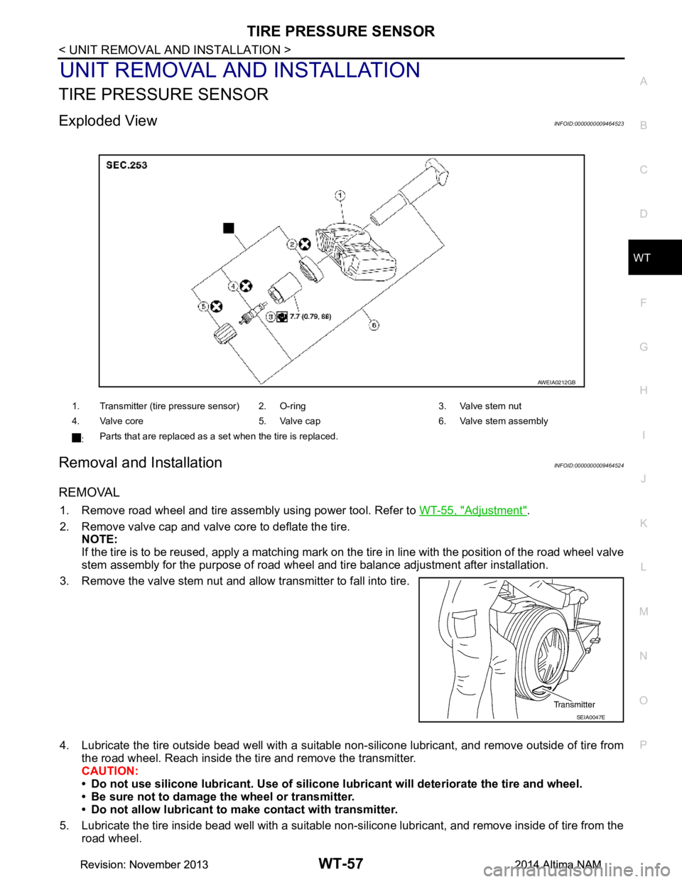
Exploded ViewINFOID:0000000009464523
Removal and InstallationINFOID:0000000009464524
REMOVAL
1. Remove road wheel and tire assembly using power tool. Refer to WT-55, "Adjustment".
2. Remove valve cap and valve core to deflate the tire. NOTE:
If the tire is to be reused, apply a matching mark on t he tire in line with the position of the road wheel valve
stem assembly for the purpose of road wheel and tire balance adjustment after installation.
3. Remove the valve stem nut and allow transmitter to fall into tire.
4. Lubricate the tire outside bead well with a suitable non-silicone lubricant, and remove outside of tire from the road wheel. Reach inside the ti re and remove the transmitter.
CAUTION:
• Do not use silicone lubricant. Use of silicone lubricant will deteriorate the tire and wheel.
• Be sure not to damage the wheel or transmitter.
• Do not allow lubricant to make contact with transmitter.
5. Lubricate the tire inside bead well with a suitable non-silicone lubricant, and remove inside of tire from the road wheel.
1. Transmitter (tire pressure sensor) 2. O-ring 3. Valve stem nut
4. Valve core 5. Valve cap 6. Valve stem assembly
: Parts that are replaced as a set when the tire is replaced.
AWEIA0212GB
SEIA0047E
Revision: November 20132014 Altima NAMRevision: November 20132014 Altima NAM
Page 4733 of 4801

WT-58
< UNIT REMOVAL AND INSTALLATION >
TIRE PRESSURE SENSOR
CAUTION:
• Do not use silicone lubricant. Use of silicone lubricant will deteriorate the tire and wheel.
• Be sure not to damage the wheel.
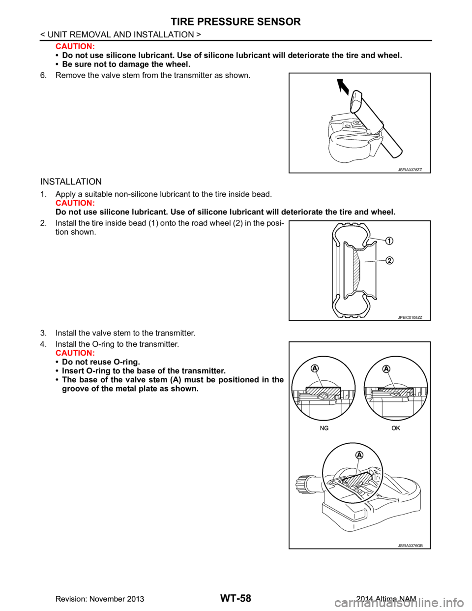
6. Remove the valve stem from the transmitter as shown.
INSTALLATION
1. Apply a suitable non-silicone lubricant to the tire inside bead.
CAUTION:
Do not use silicone lubr icant. Use of silicone lubricant wi ll deteriorate the tire and wheel.
2. Install the tire inside bead (1) onto the road wheel (2) in the posi- tion shown.
3. Install the valve stem to the transmitter.
4. Install the O-ring to the transmitter. CAUTION:
• Do not reuse O-ring.
• Insert O-ring to the base of the transmitter.
• The base of the valve stem (A) must be positioned in the groove of the metal plate as shown.
JSEIA0378ZZ
JPEIC0105ZZ
JSEIA0376GB
Revision: November 20132014 Altima NAMRevision: November 20132014 Altima NAM
Page 4734 of 4801

TIRE PRESSURE SENSORWT-59
< UNIT REMOVAL AND INSTALLATION >
C
D
F
G H
I
J
K L
M A
B
WT
N
O P
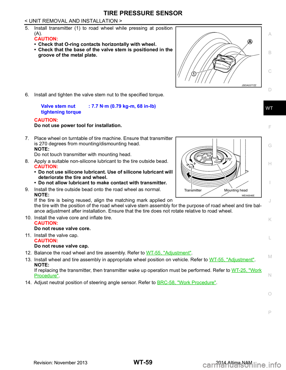
5. Install transmitter (1) to road wheel while pressing at position (A).
CAUTION:
• Check that O-ring contacts horizontally with wheel.
• Check that the base of the valve stem is positioned in the
groove of the metal plate.
6. Install and tighten the valve stem nut to the specified torque. CAUTION:
Do not use power tool for installation.
7. Place wheel on turntable of tire machine. Ensure that transmitter
is 270 degrees from mounting/dismounting head.
NOTE:
Do not touch transmitter with mounting head.
8. Apply a suitable non-silicone lubricant to the tire outside bead. CAUTION:
• Do not use silicone lubricant. Use of silicone lubricant will
deteriorate the tire and wheel.
• Do not allow lubricant to make contact with transmitter.
9. Install the tire outside bead onto the road wheel as normal. NOTE:
If the tire is being reused, align the matching mark applied on
the tire with the position of the road wheel valve st em assembly for the purpose of road wheel and tire bal-
ance adjustment after installation. Ensure that the tire does not rotate relative to road wheel.
10. Install the valve core and inflate tire. CAUTION:
Do not reuse valve core.
11. Install the valve cap. CAUTION:
Do not reuse valve cap.
12. Balance the road wheel and tire assembly. Refer to WT-55, "Adjustment"
.
13. Install wheel and tire assembly in appropriate wheel position on vehicle. Refer to WT-55, "Adjustment"
.
NOTE:
If replacing the transmitter, then transmitter wake up operation must be performed. Refer to WT-25, "Work
Procedure".
14. Adjust neutral position of steering angle sensor. Refer to BRC-58, "Work Procedure"
.
JSEIA0377ZZ
Valve stem nut
tightening torque : 7.7 N·m (0.79 kg-m, 68 in-lb)
WEIA0046E
Revision: November 20132014 Altima NAMRevision: November 20132014 Altima NAM
Page 4738 of 4801

PRECAUTIONSWW-3
< PRECAUTION >
C
D E
F
G H
I
J
K
M A
B
WW
N
O P
PRECAUTION
PRECAUTIONS
Precaution for Supplemental Restraint System (SRS) "AIR BAG" and "SEAT BELT
PRE-TENSIONER"
INFOID:0000000009951588
The Supplemental Restraint System such as “A IR BAG” and “SEAT BELT PRE-TENSIONER”, used along
with a front seat belt, helps to reduce the risk or severi ty of injury to the driver and front passenger for certain
types of collision. Information necessary to service t he system safely is included in the SR and SB section of
this Service Manual.
WARNING:
• To avoid rendering the SRS inoper ative, which could increase the risk of personal injury or death in
the event of a collision which would result in air bag inflation, all maintenance must be performed by
an authorized NISSAN/INFINITI dealer.
• Improper maintenance, including in correct removal and installation of the SRS, can lead to personal
injury caused by unintentional act ivation of the system. For removal of Spiral Cable and Air Bag
Module, see the SR section.
• Do not use electrical test equipm ent on any circuit related to the SRS unless instructed to in this
Service Manual. SRS wiring harnesses can be identi fied by yellow and/or orange harnesses or har-
ness connectors.
PRECAUTIONS WHEN USING POWER TOOLS (AIR OR ELECTRIC) AND HAMMERS
WARNING:
• When working near the Airbag Diagnosis Sensor Un it or other Airbag System sensors with the Igni-
tion ON or engine running, DO NOT use air or el ectric power tools or strike near the sensor(s) with a
hammer. Heavy vibration could activate the sensor( s) and deploy the air bag(s), possibly causing
serious injury.
• When using air or electric power tools or hammers , always switch the Ignition OFF, disconnect the
battery and wait at least three mi nutes before performing any service.
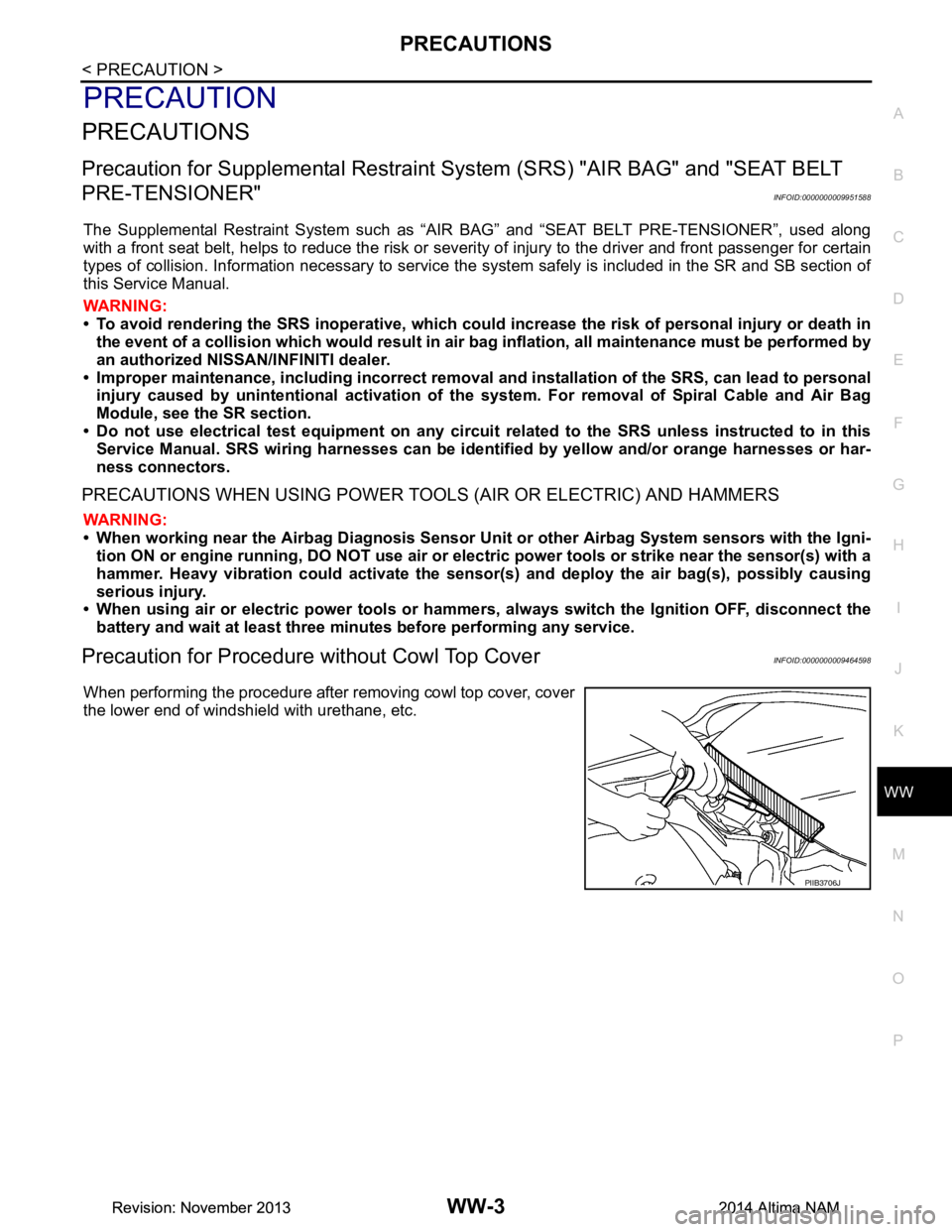
Precaution for Procedure without Cowl Top CoverINFOID:0000000009464598
When performing the procedure after removing cowl top cover, cover
the lower end of windshield with urethane, etc.
PIIB3706J
Revision: November 20132014 Altima NAMRevision: November 20132014 Altima NAM