Page 3281 of 4801
MWI-26
< ECU DIAGNOSIS INFORMATION >
COMBINATION METER
31
(W) Ground Ambient sensor ground
(without auto A/C) InputIgnition
switch
ON —0 V
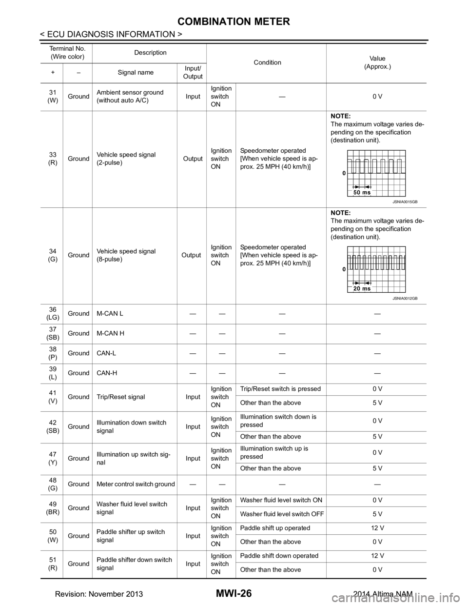
33
(R) Ground Vehicle speed signal
(2-pulse) OutputIgnition
switch
ON Speedometer operated
[When vehicle speed is ap-
prox. 25 MPH (40 km/h)] NOTE:
The maximum voltage varies de-
pending on the specification
(destination unit).
34
(G) Ground Vehicle speed signal
(8-pulse) OutputIgnition
switch
ON Speedometer operated
[When vehicle speed is ap-
prox. 25 MPH (40 km/h)] NOTE:
The maximum voltage varies de-
pending on the specification
(destination unit).
36
(LG) Ground M-CAN L — — — —
37
(SB) Ground M-CAN H — — — —
38
(P) Ground CAN-L — — — —
39
(L) Ground CAN-H — — — —
41
(V) Ground Trip/Reset signal Input Ignition
switch
ON Trip/Reset switch is pressed 0 V
Other than the above 5 V
42
(SB) Ground Illumination down switch
signal InputIgnition
switch
ON Illumination switch down is
pressed 0 V
Other than the above 5 V
47
(Y) Ground
Illumination up switch sig-
nal InputIgnition
switch
ON Illumination switch up is
pressed 0 V
Other than the above 5 V
48
(G) Ground Meter control switch ground — — — —
49
(BR) Ground Washer fluid level switch
signal InputIgnition
switch
ON Washer fluid level switch ON 0 V
Washer fluid level switch OFF 5 V
50
(W) Ground
Paddle shifter up switch
signal InputIgnition
switch
ON Paddle shift up operated 12 V
Other than the above 0 V
51
(R) Ground Paddle shifter down switch
signal InputIgnition
switch
ON Paddle shift down operated 12 V
Other than the above 0 V
Te r m i n a l N o .
(Wire color) Description
ConditionVa l u e
(Approx.)
+ – Signal name Input/
Output
JSNIA0015GB
JSNIA0012GB
Revision: November 20132014 Altima NAMRevision: November 20132014 Altima NAM
Page 3311 of 4801
MWI-56
< DTC/CIRCUIT DIAGNOSIS >
B2267 ENGINE SPEED
B2267 ENGINE SPEED
DescriptionINFOID:0000000009461709
The engine speed signal is transmitted from ECM to the combination meter via CAN communication.
DTC LogicINFOID:0000000009461710
DTC DETECTION LOGIC
Diagnosis ProcedureINFOID:0000000009461711
1.PERFORM SELF-DIAGNOSIS OF ECM
Perform Self Diagnostic Result of ECM, and repair or replace malfunctioning parts.
>> Refer to (QR25DE) EC-77, "CONSULT Function"
or (VQ35DE) EC-601, "CONSULT Function".
DTC CONSULT Detection condition Possible malfunction location
B2267 TACHO METER ECM continuously transmits abnormal engine
speed signals for 2 seconds or more • Crankshaft position sensor (POS)
•ECM
Revision: November 20132014 Altima NAMRevision: November 20132014 Altima NAM
Page 3312 of 4801
MWI
B2268 WATER TEMPMWI-57
< DTC/CIRCUIT DIAGNOSIS >
C
D E
F
G H
I
J
K L
M B
A
O P
B2268 WATER TEMP
DescriptionINFOID:0000000009461712
The engine coolant temperature signal is transmitted fr om ECM to the combination meter via CAN communi-
cation.
DTC LogicINFOID:0000000009461713
DTC DETECTION LOGIC
Diagnosis ProcedureINFOID:0000000009461714
1.PERFORM SELF-DIAGNOSIS OF ECM
Perform Self Diagnostic Result of ECM, and repair or replace malfunctioning parts.
>> Refer to (QR25DE) EC-77, "CONSULT Function"
or (VQ35DE) EC-601, "CONSULT Function".
DTC CONSULT Detection condition Probable malfunction location
B2268 WATER TEMP METER ECM continuously transmits abnormal engine coolant
temperature signals for 60 seconds or more • Engine coolant temperature sensor
•ECM
Revision: November 20132014 Altima NAMRevision: November 20132014 Altima NAM
Page 3316 of 4801
MWI
FUEL LEVEL SENSOR SIGNAL CIRCUITMWI-61
< DTC/CIRCUIT DIAGNOSIS >
C
D E
F
G H
I
J
K L
M B
A
O P
FUEL LEVEL SENSOR SIGNAL CIRCUIT
DescriptionINFOID:0000000009461718
The fuel level sensor unit and fuel pump detects the approx imate fuel level in the fuel tank and transmits the
fuel level signal to the combination meter.
Component Function CheckINFOID:0000000009461719
1.COMBINATION METER INPUT SIGNAL
1. Select METER/M&A on CONSULT.
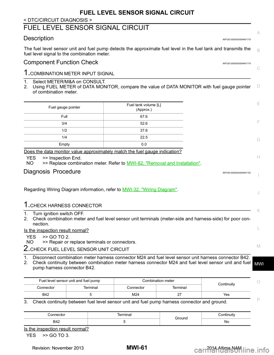
2. Using FUEL METER of DATA MONITOR, compare the value of DATA MONITOR with fuel gauge pointer
of combination meter.
Does the data monitor value approxim ately match the fuel gauge indication?
YES >> Inspection End.
NO >> Replace combination meter. Refer to MWI-82, "Removal and Installation"
.
Diagnosis ProcedureINFOID:0000000009461720
Regarding Wiring Diagram information, refer to MWI-32, "Wiring Diagram".
1.CHECK HARNESS CONNECTOR
1. Turn ignition switch OFF.
2. Check combination meter and fuel level sensor uni t terminals (meter-side and harness-side) for poor con-
nection.
Is the inspection result normal?
YES >> GO TO 2.
NO >> Repair or replace terminals or connectors.
2.CHECK FUEL LEVEL SENSOR UNIT CIRCUIT
1. Disconnect combination meter harness connector M24 and fuel level sensor unit harness connector B42.
2. Check continuity between combination meter harne ss connector M24 and fuel level sensor unit and fuel
pump harness connector B42.
3. Check continuity between fuel level sens or unit and fuel pump harness connector and ground.
Is the inspection result normal?
YES >> GO TO 3.
Fuel gauge pointer Fuel tank volume [L]
(Approx.)
Full 67.6 3/4 52.6
1/2 37.6
1/4 22.5
Empty 0.0
Fuel level sensor unit and fuel pump Combination meter Continuity
Connector Terminal Connector Terminal
B42 5 M24 27 Yes
Connector Terminal GroundContinuity
B42 5 No
Revision: November 20132014 Altima NAMRevision: November 20132014 Altima NAM
Page 3317 of 4801
MWI-62
< DTC/CIRCUIT DIAGNOSIS >
FUEL LEVEL SENSOR SIGNAL CIRCUIT
NO >> Repair or replace harness or connectors.
3.CHECK FUEL LEVEL SENSOR UNIT GROUND CIRCUIT
1. Check continuity between combination meter harnes s connector M24 and fuel level sensor unit and fuel
pump harness connector B42.
2. Check continuity between fuel level sens or unit and fuel pump harness connector and ground.
Is the inspection result normal?
YES >> GO TO 4.
NO >> Repair or replace harness or connectors.
4.CHECK INSTALLATION CONDITION
Check fuel level sensor unit installation, and check whether the float arm interferes or binds with any of the
internal components in the fuel tank.
Is the inspection result normal?
YES >> Inspection End.
NO >> Install the fuel level sensor unit properly. Refer to FL-6, "Removal and Installation"
.
Component InspectionINFOID:0000000009461721
1.REMOVE FUEL LEVEL SENSOR UNIT
Remove the fuel level sensor unit. Refer to FL-6, "Removal and Installation"
.
>> GO TO 2
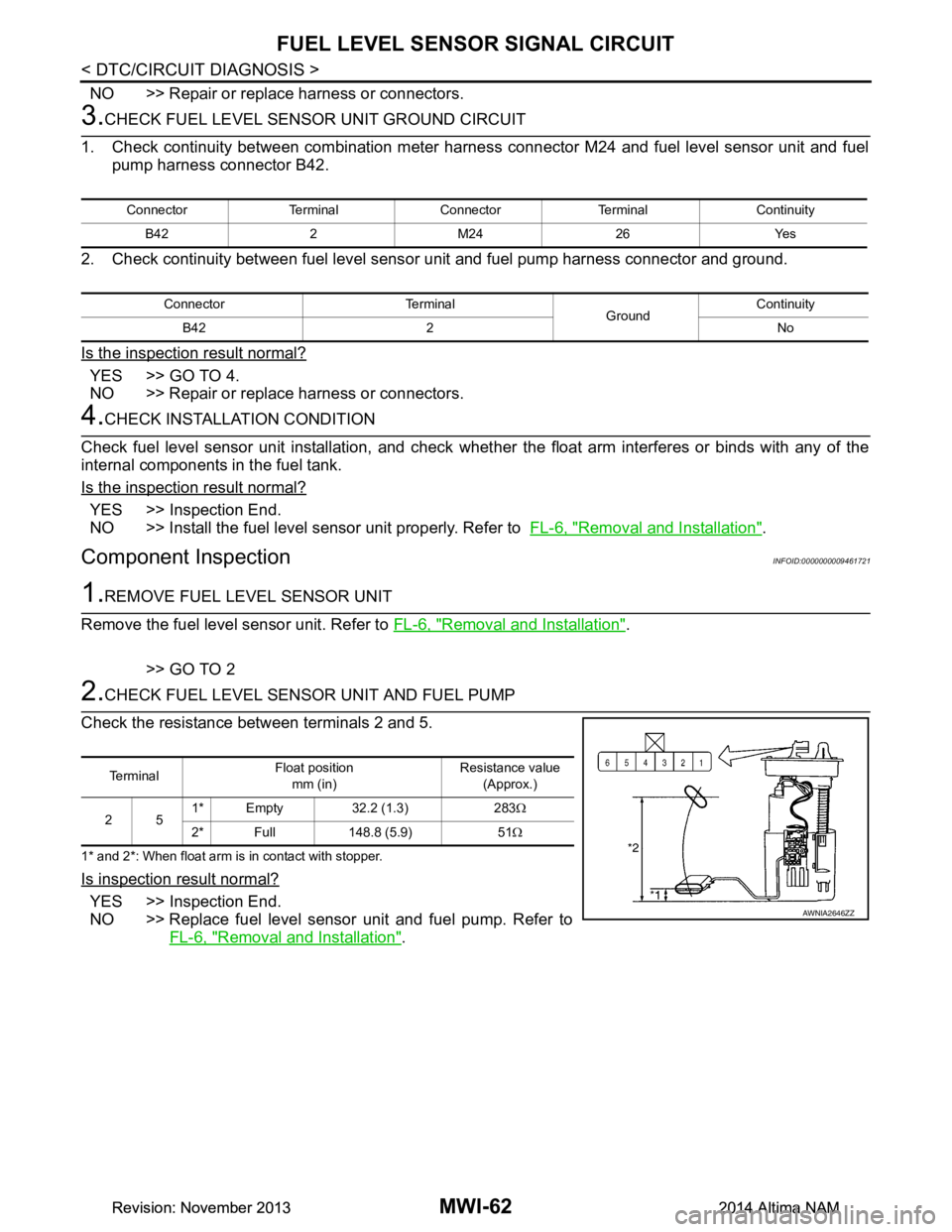
2.CHECK FUEL LEVEL SENSOR UNIT AND FUEL PUMP
Check the resistance between terminals 2 and 5.
1* and 2*: When float arm is in contact with stopper.
Is inspection result normal?
YES >> Inspection End.
NO >> Replace fuel level sensor unit and fuel pump. Refer to FL-6, "Removal and Installation"
.
Connector Terminal Connector Terminal Continuity
B42 2 M24 26 Yes
Connector Terminal GroundContinuity
B42 2 No
Te r m i n a l Float position
mm (in) Resistance value
(Approx.)
25 1* Empty 32.2 (1.3) 283
Ω
2* Full 148.8 (5.9) 51 Ω
AWNIA2646ZZ
Revision: November 20132014 Altima NAMRevision: November 20132014 Altima NAM
Page 3321 of 4801
MWI-66
< DTC/CIRCUIT DIAGNOSIS >
AMBIENT SENSOR SIGNAL CIRCUIT
AMBIENT SENSOR SIGNAL CIRCUIT
DescriptionINFOID:0000000009461729
Transmits the ambient sensor signal to the IPDM E/R.
Component Function CheckINFOID:0000000009461730
1.COMBINATION METER INPUT SIGNAL
1. Select METER/M&A on CONSULT.
2. Check OUTSIDE TEMP on DATA MONITOR.
Does the ambient temperature approx imately match the CONSULT display?
YES >> Replace combination meter. Refer to MWI-82, "Removal and Installation".
NO >> Refer to MWI-66, "Diagnosis Procedure"
.
Diagnosis ProcedureINFOID:0000000009461731
Regarding Wiring Diagram information, refer to MWI-32, "Wiring Diagram".
1.CHECK AMBIENT SENSOR CIRCUITS BETWEE N COMBINATION METER AND IPDM E/R
1. Disconnect combination meter connecto r M24 and IPDM E/R connector E63.
2. Check continuity between combination meter har ness connector M24 terminals 30, 31 and IPDM E/R har-
ness connector E63 terminals 49 and 50.
3. Check continuity between combination mete r harness connector M24 terminals 30, 31 and ground.
Is the inspection result normal?
YES >> GO TO 2.
NO >> Repair or replace harness or connector.
2.CHECK AMBIENT SENSOR CIRCUITS BETW EEN IPDM E/R AND AMBIENT SENSOR
1. Disconnect IPDM E/R connector E201 and ambient sensor connector E211.
2. Check continuity between IPDM E/R harness connec tor E201 terminals 87, 95 and ambient sensor har-
ness connector E211 terminals 1 and 2.
3. Check continuity between IPDM E/R har ness connector E201 terminals 87, 95 and ground.
Is the inspection result normal?
Connector Terminal Connector Terminal Continuity M24 30
E63 49
Ye s
31 50
Connector Terminal Continuity M24 30
No
31
Connector Terminal Connector Terminal Continuity
E201 87
E211 1
Ye s
95 2
Connector Terminal Continuity E201 87 No
95
Revision: November 20132014 Altima NAMRevision: November 20132014 Altima NAM
Page 3322 of 4801
MWI
AMBIENT SENSOR SIGNAL CIRCUITMWI-67
< DTC/CIRCUIT DIAGNOSIS >
C
D E
F
G H
I
J
K L
M B
A
O P
YES >> Replace IPDM E/R. Refer to PCS-32, "Removal and Installation".
NO >> Repair or replace harness or connector.
Component InspectionINFOID:0000000009461732
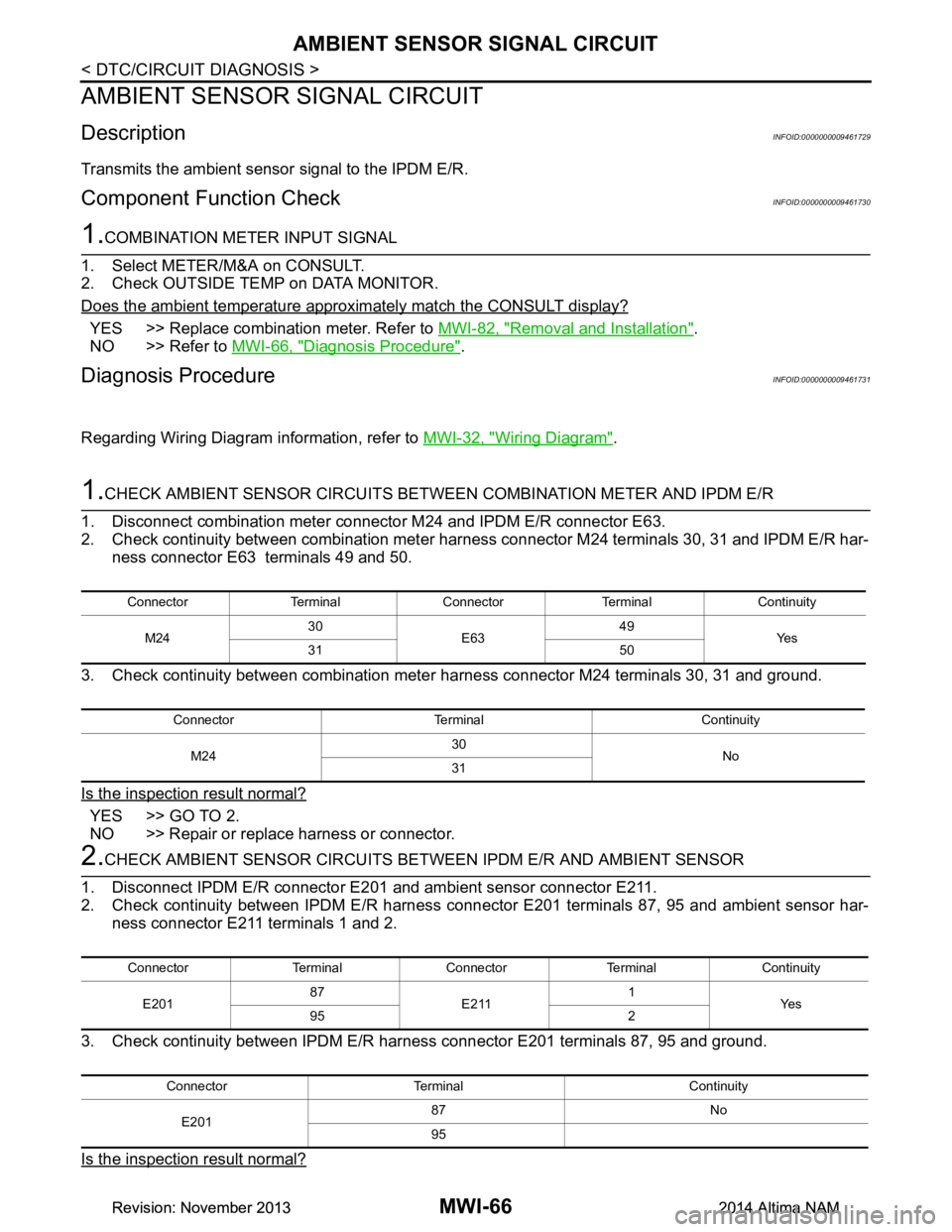
1.CHECK AMBIENT SENSOR
1. Turn ignition switch OFF.
2. Disconnect ambient sensor connector.
3. Check resistance between ambient sensor terminals.
Is the inspection result normal?
YES >> Inspection End.
NO >> Replace ambient sensor. Refer to MWI-83, "Removal and Installation"
.
Te r m i n a lCondition
Resistance: kΩ
Temperature: °C ( °F)
12 −
15 (5) 12.73
− 10 (14) 9.92
− 5 (23) 7.80
0 (32) 6.19
5 (41) 4.95
10 (50) 3.99
15 (59) 3.24
20 (68) 2.65
25 (77) 2.19
30 (86) 1.81
35 (95) 1.51
40 (104) 1.27 45 (113) 1.07
Revision: November 20132014 Altima NAMRevision: November 20132014 Altima NAM
Page 3327 of 4801
MWI-72
< SYMPTOM DIAGNOSIS >
THE FUEL GAUGE INDICATOR DOES NOT OPERATE
SYMPTOM DIAGNOSIS
THE FUEL GAUGE INDICATOR DOES NOT OPERATE
DescriptionINFOID:0000000009461738
Fuel gauge will not indicate from a certain position.
Diagnosis ProcedureINFOID:0000000009461739
1.CHECK COMBINATION METER INPUT SIGNAL
Perform component function check. Refer to MWI-61, "Component Function Check"
.
Does monitor value match fuel gauge reading?
YES >> GO TO 2.
NO >> Replace combination meter. Refer to MWI-82, "Removal and Installation"
.
2.CHECK FUEL LEVEL SENSOR UNIT CIRCUITS
Check the fuel level sensor circuits. Refer to MWI-61, "Diagnosis Procedure"
.
Is the inspection result normal?
YES >> GO TO 3.
NO >> Repair or replace harness or connectors.
3.CHECK FUEL LEVEL SENSOR UNIT
Perform a unit check for the fuel level sensor unit. Refer to MWI-62, "Component Inspection"
.
Is the inspection result normal?
YES >> GO TO 4.
NO >> Replace fuel level sensor unit. Refer to FL-6, "Removal and Installation"
.
4.CHECK FLOAT INTERFERENCE
Check that the float arm does not interfere with or binds to other components in the fuel tank.
Is the inspection result normal?
YES >> Replace combination meter. Refer to MWI-82, "Removal and Installation".
NO >> Repair or replace malfunctioning parts.
Revision: November 20132014 Altima NAMRevision: November 20132014 Altima NAM