2014 NISSAN TEANA sensor
[x] Cancel search: sensorPage 3476 of 4801

PG-44
< DTC/CIRCUIT DIAGNOSIS >
HARNESS
F3 E10 GR/32 : ECM (QR25DE except for California) B3 E41 GR/2 : Front wheel sensor RH
F2 E11 W/16 : To F2 F1 E42 BR/6 : Cooling fan relay-2
F2 E12 W/6 : To E203 G2 E43 BR/6 : Cooling fan relay-3
F2 E13 Y/4 : To E205 B2 E54 B/38 : ABS actuator and electric unit (Control
unit)
E2 E15 — : Body ground G2 E5 7 L / 4 : S t o p l a m p r e l a y
E1 E16 B/2 : IPDM E/R (Intelligent power distribution
module engine room) C3 E59 B/6 : Power steering control module
E1 E17 W/4 : IPDM E/R (Intelligent power distribution
module engine room) C4 E60 B/2 : Power steering control module
E1 E18 W/12 : IPDM E/R (Intelligent power distribution
module engine room) B3 E61 — : Body ground
E1 E19 GR/2 : Front wheel sensor LH F2 E62 B/1 : Fusible link box (Battery)
F 1 E 2 1 G R / 6 : J o i n t c o n n e c t o r - E 0 3 F 1 E 6 3 W / 3 2 : IPDM E/R (Intelligent power distribution
module engine room)
F1 E22 GR/6 : Joint connector-E04 E1 E73 BR/3 : Outside warning buzzer
F2 E23 BR/8 : To F25 E1 E74 BR/3 : Intelligent Key warning buzzer
D1 E24 GR/2 : Brake fluid level switch
Revision: November 20132014 Altima NAM
Page 3477 of 4801

PG
HARNESSPG-45
< DTC/CIRCUIT DIAGNOSIS >
C
D E
F
G H
I
J
K L
B
A
O P
N
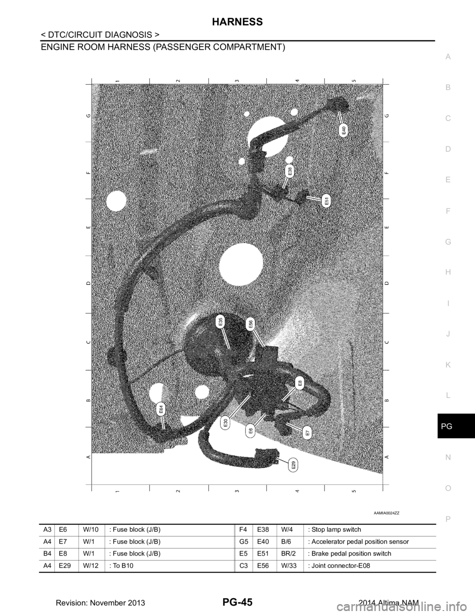
ENGINE ROOM HARNESS (PASSENGER COMPARTMENT)
AAMIA0024ZZ
A3 E6 W/10 : Fuse block (J/B) F4 E38 W/4 : Stop lamp switch
A4 E7 W/1 : Fuse block (J/B) G5 E40 B/6 : Accelerator pedal position sensor
B4 E8 W/1 : Fuse block (J/B) E5 E51 BR/2 : Brake pedal position switch
A4 E29 W/12 : To B10 C3 E56 W/33 : Joint connector-E08
Revision: November 20132014 Altima NAM
Page 3479 of 4801

PG
HARNESSPG-47
< DTC/CIRCUIT DIAGNOSIS >
C
D E
F
G H
I
J
K L
B
A
O P
N
E3 E202 W/8 : To E2 E5 E231 GR/4 : To E301
F4 E203 W/6 : To E12 F4 E232 GR/2 : Front combination lamp LH (With xenon
headlamp system)
F4 E204 — : Body ground A3 E233 B/6 : To E350
E3 E205 Y/4 : To E13 E5 E234 B/2 : Front fog lamp LH
B3 E208 B/2 : Washer fluid level switch F4 E235 GR/2 : Front combination lamp LH
B2 E209 — : Body ground A2 E236 GR/2 : Front combination lamp RH
C4 E210 Y/2 : Crash zone sensor B4 E237 B/2 : Front fog lamp RH
D5 E211 B/2 : Ambient sensor D5 E238 B/1 : Horn (Low)
F4 E212 B/2 : Front combination lamp LH (Without
xenon headlamp system) E5 E239 B/1 : Horn (High)
E4 E213 B/2 : Front combination lamp LH A4 E240 GR/4 : To E305
F5 E214 B/2 : Front fog lamp LH B2 E243 GR/2 : Front combination lamp RH (With xenon
headlamp system)
D4 E215 B/1 : Horn (Low) C3 E248 B/3 : Hood switch or pre-wiring for hood
switch
E4 E216 B/1 : Horn (High) Front fog lamp sub-harness
E5 E217 GR/3 : Front combination lamp LH E5 E301 GR/4 : To E231
D4 E219 B/3 : Refrigerant pressure sensor E5 E303 B/2 : Pre-wiring for front fog lamp LH
D4 E220 GR/4 : Cooling fan motor-1 A4 E305 GR/4 : To E240
D4 E221 GR/4 : Cooling fan motor-2 B4 E306 B/2 : Pre-wiring for front fog lamp RH
B3 E222 B/2 : Front combination lamp RH Front combination lamp sub-harness
B2 E223 B/2 : Front combination lamp RH (Without
xenon headlamp system) A3 E350 B/6 : To E233
A 3 E 2 2 4 G R / 3 : Front combination lamp RH (Without front
fog lamps) B3 E351 GR/3
: Front combination lamp RH (With front
fog lamps)
B4 E226 B/2 : Front washer motor
Revision: November 20132014 Altima NAM
Page 3480 of 4801

PG-48
< DTC/CIRCUIT DIAGNOSIS >
HARNESS
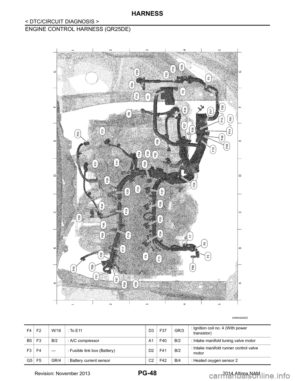
ENGINE CONTROL HARNESS (QR25DE)
AAMIA0026ZZ
F 4 F 2 W / 1 6 : To E 11 D 3 F 3 7 G R / 3: Ignition coil no. 4 (With power
transistor)
B5 F3 B/2 : A/C compressor A1 F40 B/2 : Intake manifold tuning valve motor
F3 F4 — : Fusible link box (Battery) D2 F41 B/2 : Intake manifold runner control valve
motor
G5 F5 GR/4 : Battery current sensor C2 F42 B/4 : Heated oxygen sensor 2
Revision: November 20132014 Altima NAM
Page 3481 of 4801

PG
HARNESSPG-49
< DTC/CIRCUIT DIAGNOSIS >
C
D E
F
G H
I
J
K L
B
A
O P
N
B5 F6 — : Generator C2 F45 GR/2 : Knock sensor
B4 F7 B/3 : Generator F4 F46 GR/22 : CVT unit
F2 F8 B/3 : Primary speed sensor F5 F47 B/6 : Joint connector-F01
B3 F9 — : Engine ground E5 F48 B/10 : Joint connector-F02
F 3 F 1 0 B / 1 : IPDM E/R (Intelligent power distribution
module engine room) E5 F49 B/10 : Joint connector-F03
F 5 F 1 3 B R / 4 8 : E C M ( Q R 2 5 D E e x c e p t f o r C a l i f o r n i a ) A 2 F 5 1 G / 2 : Intake valve timing intermediate lock
control solenoid valve
E5 F14 B/48 : ECM (QR25DE except for California) B2 F52 B/3 : Intake manifold runner control valve
position sensor
B3 F15 — : Engine ground G4 F53 W/4 : Joint connector-F07
E5 F16 B/48 : TCM (Transmission control module) E3 F54 GR/2 : Engine coolant temperature sensor (With
QR25DE)
B2 F17 GR/2 : Fuel injector no. 1 D3 F55 B/3 : Camshaft position sensor (PHASE)
B2 F18 GR/2 : Fuel injector no. 2 D2 F57 B/6 : Electric throttle control actuator
C 2 F 1 9 G R / 2 : F u e l i n j e c t o r n o . 3 D 3 F 5 8 B / 3 : Exhaust valve timing control position
sensor
D 2 F 2 0 G R / 2 : F u e l i n j e c t o r n o . 4 A 2 F 5 9 G / 2 : Intake valve timing control solenoid
valve
E1 F23 B/3 : Output speed sensor B2 F68 GR/2 : Engine oil temperature sensor
D4 F24 GR/4 : Air fuel ratio (A/F) sensor 1 G4 F70 W/4 : Joint connector-F08
G 4 F 2 5 B R / 8 : To E 2 3 A 3 F 8 0 G / 2 : Exhaust valve timing control solenoid
valve
E 3 F 2 6 W / 2 : C o n d e n s e r G 3 F 8 3 W / 1 0 : IPDM E/R (Intelligent power distribution
module engine room)
E 4 F 2 7 — : S t a r t e r m o t o r G 3 F 8 4 W / 1 2 : IPDM E/R (Intelligent power distribution
module engine room)
E4 F28 — : Starter motor (With QR25DE) E3 F85 B/10 : Transmission range switch
C 1 F 2 9 L / 2 : EVAP canister purge volume control
solenoid valve (With QR25DE) E3 F86 B/3 : Input speed sensor
D2 F30 B/3 : Crankshaft position sensor (POS) A2 F87 B/3 : Engine oil pressure sensor
E2 F31 GR/6 : Mass air flow sensor (With QR25DE) A4 F88 GR/2 : A/C compressor
B 3 F 3 4 G R / 3 : Ignition coil no. 1 (With power
transistor) A1 F89 B/3 : Manifold absolute pressure (Map) sensor
C 3 F 3 5 G R / 3 : Ignition coil no. 2 (With power
transistor) F5 F90 BR/48 : ECM (QR25DE for California)
C 3 F 3 6 G R / 3 : Ignition coil no. 3 (With power
transistor) F5 F91 B/48 : ECM (QR25DE for California)
Revision: November 20132014 Altima NAM
Page 3482 of 4801

PG-50
< DTC/CIRCUIT DIAGNOSIS >
HARNESS
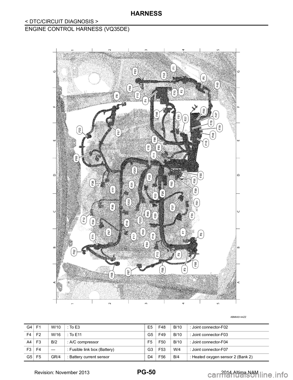
ENGINE CONTROL HARNESS (VQ35DE)
ABMIA5144ZZ
G4 F1 W/10 : To E3 E5 F48 B/10 : Joint connector-F02
F4 F2 W/16 : To E11 G5 F49 B/10 : Joint connector-F03
A4 F3 B/2 : A/C compressor F5 F50 B/10 : Joint connector-F04
F3 F4 — : Fusible link box (Battery) G3 F53 W/4 : Joint connector-F07
G5 F5 GR/4 : Battery current sensor D4 F56 B/4 : Heated oxygen sensor 2 (Bank 2)
Revision: November 20132014 Altima NAM
Page 3483 of 4801

PG
HARNESSPG-51
< DTC/CIRCUIT DIAGNOSIS >
C
D E
F
G H
I
J
K L
B
A
O P
N
B5 F6 — : Generator E2 F57 B/6 : Electric throttle control actuator
B 4 F 7 B / 3 : G e n e r a t o r D 4 F 6 0 B / 3 : Camshaft position sensor (PHASE)
(Bank 2)
F2 F8 B/3 : Primary speed sensor C4 F61 GR/4 : Air fuel ratio (A/F) sensor (Bank 2)
B4 F9 — : Engine ground B1 F62 B/4 : Heated oxygen sensor 2 (Bank 1)
F 3 F 1 0 B / 1 : IPDM E/R (Intelligent power distribution
module engine room) B3 F63 B/2 : VIAS
control solenoid valve 1
E3 F11 GR/2 : Engine coolant temperature sensor B3 F64 BR/2 : Electronic controlled engine mount
control solenoid valve
C1 F12 GR/4 : Air fuel ratio (A/F) sensor (Ban k 1) C3 F65 B/2 : VIAS control solenoid valve 2
B 3 F 1 5 — : E n g i n e g r o u n d A 3 F 6 6 G / 2 : Intake valve timing control solenoid
valve (Bank 2)
E5 F16 B/48 : TCM (Transmission control module) B2 F67 G/2 : Intake valve timing control solenoid
valve (Bank 1)
B3 F17 GR/2 : Fuel injector no. 1 A2 F68 GR/2 : Engine oil temperature sensor
B3 F18 GR/2 : Fuel injector no. 2 F4 F70 W/4 : Joint connector-F08
C2 F19 GR/2 : Fuel injector no. 3 B2 F71 G/6 : Joint connector-F09
C3 F20 GR/2 : Fuel injector no. 4 E3 F76 L/4 : To F201
D 3 F 2 1 G R / 2 : F u e l i n j e c t o r n o . 5 D 2 F 7 7 B / 3 : Camshaft position sensor (PHASE)
(Bank 1)
C3 F22 GR/2 : Fuel injector no. 6 F5 F78 B/48 : ECM (With VQ35DE)
E1 F23 B/3 : Output speed sensor E5 F79 BR/48 : ECM (With VQ35DE)
D3 F26 W/2 : Condenser F4 F81 GR/1 : Starter motor (With VQ35DE)
F 4 F 2 7 — : S t a r t e r m o t o r G 3 F 8 3 W / 1 0 : IPDM E/R (Intelligent power distribution
module engine room)
D5 F30 B/3 : Crankshaft position sensor (POS) G3 F84 W/12 : IPDM E/R (Intelligent power distribution
module engine room)
D 3 F 3 2 G R / 2 : EVAP canister purge volume control
solenoid valve (With VQ35DE) E3 F85 B/10 : Transmission range switch
C 2 F 3 4 G R / 3 : Ignition coil no. 1 (With power
transistor) E3 F86 B/3 : Input speed sensor
C 4 F 3 5 G R / 3 : Ignition coil no. 2 (With power
transistor) A2 F87 B/3 : Engine oil pressure sensor
C 2 F 3 6 G R / 3 : Ignition coil no. 3 (With power
transistor) A 4 F 8 8 G R / 2 : A / C c o m p r e s s o r
C 4 F 3 7 G R / 3 : Ignition coil no. 4 (With power
transistor) E1 F93 GR/6 : Mass air flow sensor (With VQ35DE)
D 2 F 3 8 G R / 3 : Ignition coil no. 5 (With power
transistor) Knock sensor sub-harness
D 4 F 3 9 G R / 3 : Ignition coil no. 6 (With power
transistor) D 3 F 2 0 1 L / 4 : T o F 7 6
F3 F46 GR/22 : CVT unit C3 F202 GR/2 : Knock sensor (Bank 1)
F5 F47 B/6 : Joint connector-F01 C3 F203 GR/2 : Knock sensor (Bank 2)
Revision: November 20132014 Altima NAM
Page 3484 of 4801

PG-52
< DTC/CIRCUIT DIAGNOSIS >
HARNESS
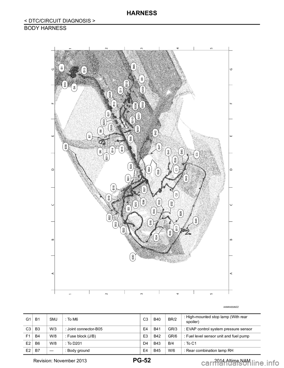
BODY HARNESS
AAMIA0028ZZ
G1 B1 SMJ : To M6 C3 B40 BR/2: High-mounted stop lamp (With rear
spoiler)
C3 B3 W/3 : Joint connector-B05 E4 B41 GR/3 : EVAP control system pressure sensor
F1 B4 W/8 : Fuse block (J/B) E3 B42 GR/6 : Fuel level sensor unit and fuel pump
E2 B6 W/8 : To D201 D4 B43 B/4 : To C1
E2 B7 — : Body ground E4 B45 W/6 : Rear combination lamp RH
Revision: November 20132014 Altima NAM