2014 NISSAN TEANA battery
[x] Cancel search: batteryPage 3850 of 4801

DIAGNOSIS SYSTEM (BCM)SEC-25
< SYSTEM DESCRIPTION >
C
D E
F
G H
I
J
L
M A
B
SEC
N
O P
IMMU
IMMU : CONSULT Function (BCM - IMMU)INFOID:0000000009955728
CAUTION:
After disconnecting the CONSULT vehicle interface (VI) from the data link connector, the ignition must
be cycled OFF → ON (for at least 5 seconds) → OFF. If this step is not performed, the BCM may not go
to ”sleep mode”, potentiall y causing a discharged battery and a no-start condition.
SELF DIAGNOSTIC RESULT
Refer to BCS-52, "DTC Index".
DATA MONITOR
ACTIVE TEST
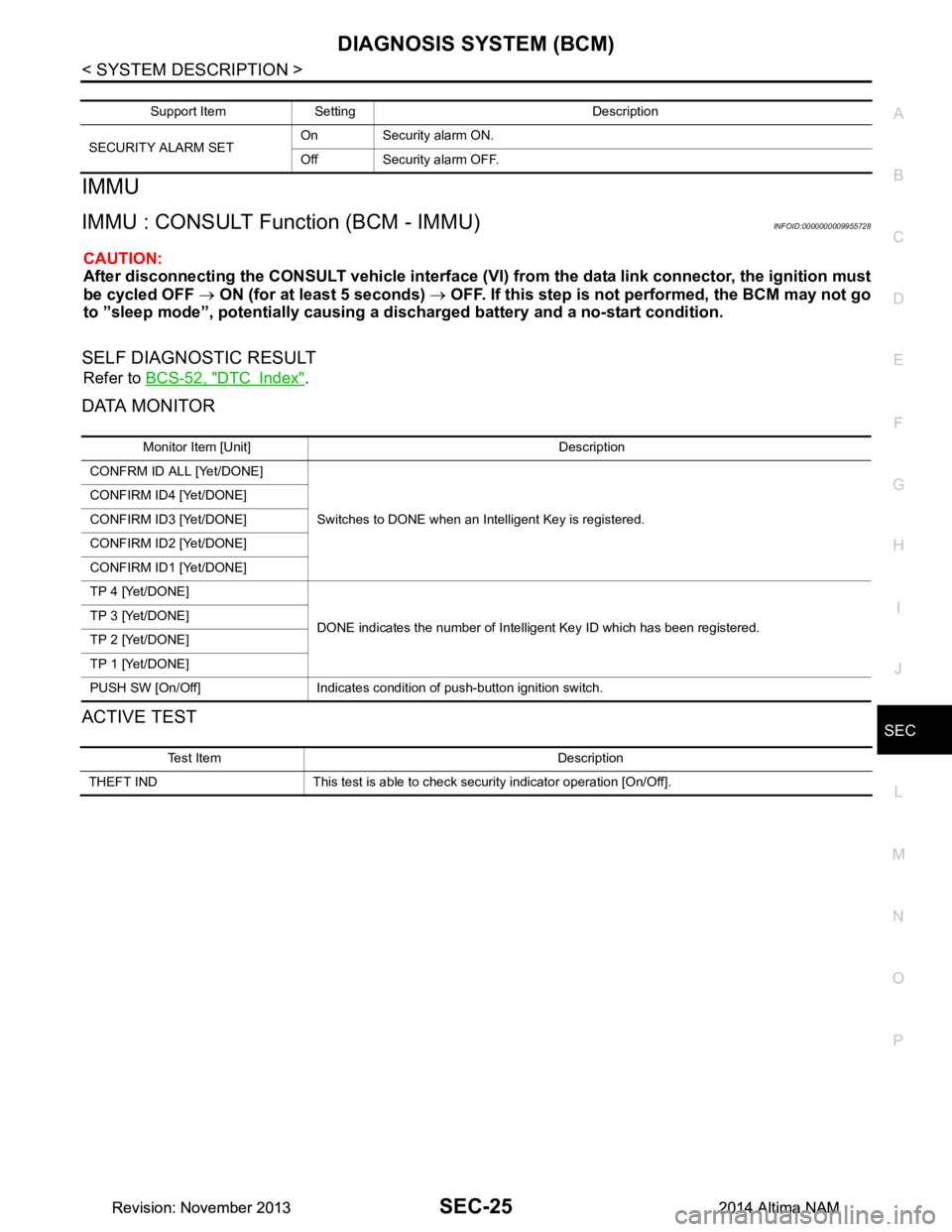
Support Item Setting Description
SECURITY ALARM SET On Security alarm ON.
Off Security alarm OFF.
Monitor Item [Unit] Description
CONFRM ID ALL [Yet/DONE]
Switches to DONE when an Intelligent Key is registered.
CONFIRM ID4 [Yet/DONE]
CONFIRM ID3 [Yet/DONE]
CONFIRM ID2 [Yet/DONE]
CONFIRM ID1 [Yet/DONE]
TP 4 [Yet/DONE]
DONE indicates the number of Intelligent Key ID which has been registered.
TP 3 [Yet/DONE]
TP 2 [Yet/DONE]
TP 1 [Yet/DONE]
PUSH SW [On/Off] Indicates condition of push-button ignition switch.
Test Item Description
THEFT IND This test is able to check security indicator operation [On/Off].
Revision: November 20132014 Altima NAMRevision: November 20132014 Altima NAM
Page 3851 of 4801

SEC-26
< SYSTEM DESCRIPTION >
DIAGNOSIS SYSTEM (IPDM E/R)
DIAGNOSIS SYSTEM (IPDM E/R)
CONSULT Function (IPDM E/R)INFOID:0000000009955729
CAUTION:
After disconnecting the CONSULT vehicle interface (VI) from the data link connector, the ignition must
be cycled OFF → ON (for at least 5 seconds) → OFF. If this step is not performed, the BCM may not go
to ”sleep mode”, potentially causing a di scharged battery and a no-start condition.
APPLICATION ITEM
CONSULT performs the following functions via CAN communication with IPDM E/R.
ECU IDENTIFICATION
The IPDM E/R part number is displayed.
SELF DIAGNOSTIC RESULT
Refer to PCS-20, "DTC Index".
DATA MONITOR
Direct Diagnostic Mode Description
Ecu Identification The IPDM E/R part number is displayed.
Self Diagnostic Result The IPDM E/R self diagnostic results are displayed.
Data Monitor The IPDM E/R input/output data is displayed in real time.
Active Test The IPDM E/R activates outputs to test components.
CAN Diag Support Mntr The result of transmit/receive diagnosis of CAN communication is displayed.
Monitor Item [Unit] Main
Signals Description
MOTOR FAN REQ [%] ×Indicates cooling fan speed signal received from ECM on CAN communication
line
AC COMP REQ [On/Off] ×Indicates A/C compressor request signal received from ECM on CAN commu-
nication line
TAIL&CLR REQ [On/Off] ×Indicates position light request signal received from BCM on CAN communica-
tion line
HL LO REQ [On/Off] ×Indicates low beam request signal received from BCM on CAN communication
line
HL HI REQ [On/Off] ×Indicates high beam request signal received from BCM on CAN communication
line
FR FOG REQ [On/Off] ×Indicates front fog light request signal received from BCM on CAN communica-
tion line
FR WIP REQ [Stop/1LOW/Low/Hi] ×Indicates front wiper request signal received from BCM on CAN communication
line
WIP AUTO STOP [STOP P/ACT P] ×Indicates condition of front wiper auto stop signal
WIP PROT [Off/BLOCK] ×Indicates condition of front wiper fail-safe operation
IGN RLY1 -REQ [On/Off] Indicates ignition switch ON signal received from BCM on CAN communication
line
IGN RLY [On/Off] ×Indicates condition of ignition relay
PUSH SW [On/Off] Indicates condition of push-button ignition switch
INTER/NP SW [On/Off] Indicates condition of CVT shift position
ST RLY CONT [On/Off] Indicates starter relay status signal received from BCM on CAN communication
line
IHBT RLY -REQ [On/Off] Indicates starter control relay signal received from BCM on CAN communication
line
Revision: November 20132014 Altima NAMRevision: November 20132014 Altima NAM
Page 3899 of 4801

SEC-74
< DTC/CIRCUIT DIAGNOSIS >
B210C STARTER CONTROL RELAY
B210C STARTER CONTROL RELAY
DTC LogicINFOID:0000000009461119
DTC DETECTION LOGIC
NOTE:
• If DTC B210C is displayed with DTC U1000, first perform the trouble diagnosis for DTC U1000. Refer to
BCS-68, "DTC Logic"
.
• If DTC B210C is displayed with DTC U1010, first perform the trouble diagnosis for DTC U1010. Refer to BCS-69, "DTC Logic"
.
• When IPDM E/R power supply voltage is low (Approx. 7 - 8 V for about 1 second), the DTC B210C may be detected.
DTC CONFIRMATION PROCEDURE
1.PERFORM DTC CONFIRMATION PROCEDURE
1. Turn the power supply position to start under the following conditions and wait for at least 1 second.
- CVT selector lever is in the P (Park) or N (Neutral) position.
- Depress the brake pedal
2. Check “Self-diagnostic result” with CONSULT.
Is DTC detected?
YES >> Refer to SEC-74, "Diagnosis Procedure".
NO >> Inspection End.
Diagnosis ProcedureINFOID:0000000009461120
Regarding Wiring Diagram information, refer to SEC-29, "Wiring Diagram".
1.PERFORM SELF DIAGNOSTIC RESULT
Perform Self Diagnostic Result of IPDM E/R using CONSULT.
Is display history of DTC B210C CRNT?
YES >> GO TO 2.
NO >> Refer to GI-43, "Intermittent Incident"
.
2.CHECK STARTER CONTROL RELA Y CONTROL CIRCUITS VOLTAGE
Check voltage between IPDM E/R connectors and ground.
Is the inspection result normal?
YES >> Replace IPDM E/R. Refer to PCS-32, "Removal and Installation".
NO >> GO TO 3.
DTC No. Trouble diagnosis
name DTC detecting condition Possible cause
B210C START CONT RLY
OFF CIRC When comparing the following items, IPDM E/R de-
tects that starter control relay is stuck in the OFF
position for 1 second or more.
• Starter contro l relay signal (CAN) from BCM
• Starter relay status signal (CAN) from BCM
• Starter control relay and starter relay status sig-
nal (IPDM E/R input)
• Starter control relay control signal (IPDM E/R
output) • IPDM E/R
•BCM
•Battery
IPDM E/R GroundVo l ta g e
(Approx.)
Connector Terminal
E63 33 — Battery voltage
Revision: November 20132014 Altima NAMRevision: November 20132014 Altima NAM
Page 3901 of 4801

SEC-76
< DTC/CIRCUIT DIAGNOSIS >
B210D STARTER RELAY
B210D STARTER RELAY
DTC LogicINFOID:0000000009461122
DTC DETECTION LOGIC
NOTE:
• If DTC B210D is displayed with DTC U1000, first perform the trouble diagnosis for DTC U1000. Refer to
BCS-68, "DTC Logic"
.
• If DTC B210D is displayed with DTC U1010, first perform the trouble diagnosis for DTC U1010. Refer to BCS-69, "DTC Logic"
.
• If DTC B210D is displayed with DTC B2617, first perform the trouble diagnosis for DTC B2617. Refer to
SEC-118, "DTC Logic"
.
DTC CONFIRMATION PROCEDURE
1.PERFORM DTC CONFIRMATION PROCEDURE
1. Ignition switch ON under the following conditions and wait for at least 1 second.
- CVT selector lever is in the P (Park) or N (Neutral) position
- Do not depress the brake pedal
2. Check “Self-diagnostic result” with CONSULT.
Is DTC detected?
YES >> Refer to SEC-76, "Diagnosis Procedure".
NO >> Inspection End.
Diagnosis ProcedureINFOID:0000000009461123
Regarding Wiring Diagram information, refer to SEC-29, "Wiring Diagram".
1. PERFORM SELF DIAGNOSTIC RESULT
Perform Self Diagnostic Result of IPDM E/R using CONSULT.
Is display history of DTC B210D CRNT?
YES >> GO TO 2.
NO >> Refer to GI-43, "Intermittent Incident"
.
2.CHECK STARTER CONTROL RELA Y CONTROL CIRCUITS VOLTAGE
Check voltage between IPDM E/R connectors and ground.
Is the inspection result normal?
YES >> Replace IPDM E/R. Refer to PCS-32, "Removal and Installation".
NO >> GO TO 3.
DTC No. Trouble diagnosis
name DTC detecting condition Possible cause
B210D STARTER RELAY
ON CIRC When comparing the following items, IPDM E/R de-
tects that starter control relay is stuck in the ON po-
sition for 5 second or more.
• Starter contro l relay signal (CAN) from BCM
• Starter relay status signal (CAN) from BCM
• Starter control relay and starter relay status sig-
nal (IPDM E/R input)
• Starter control relay control signal (IPDM E/R
output) • Harness or connectors (starter mo-
tor relay control circuit open or
short)
• IPDM E/R
•BCM
IPDM E/R GroundVo l ta g e
(Approx.)
Connector Terminal
E63 33 — Battery voltage
Revision: November 20132014 Altima NAMRevision: November 20132014 Altima NAM
Page 3903 of 4801

SEC-78
< DTC/CIRCUIT DIAGNOSIS >
B210E STARTER RELAY
B210E STARTER RELAY
DTC LogicINFOID:0000000009461125
DTC DETECTION LOGIC
NOTE:
• If DTC B210E is displayed with DTC U1000, first perform the trouble diagnosis for DTC U1000. Refer to
BCS-68, "DTC Logic"
.
• If DTC B210E is displayed with DTC U1010, first perform the trouble diagnosis for DTC U1010. Refer to
BCS-69, "DTC Logic"
.
• When IPDM E/R power supply voltage is low (Approx. 7 - 8 V for about 1 second), the DTC B210F may be
detected.
DTC CONFIRMATION PROCEDURE
1.PERFORM DTC CONFIRMATION PROCEDURE
1. Turn ignition switch ON under the following conditions and wait for at least 1 second.
- CVT selector lever is in the P (Park) or N (Neutral) position
- Do not depress the brake pedal
2. Check Self-diagnostic result with CONSULT.
Is DTC detected?
YES >> Refer to SEC-78, "Diagnosis Procedure".
NO >> Inspection End.
Diagnosis ProcedureINFOID:0000000009461126
Regarding Wiring Diagram information, refer to SEC-29, "Wiring Diagram".
1. PERFORM SELF DIAGNOSTIC RESULT
Perform Self Diagnostic Result of IPDM E/R using CONSULT.
Is display history of DTC B210E CRNT?
YES >> GO TO 2.
NO >> Refer to GI-43, "Intermittent Incident"
.
2.CHECK STARTER CONTROL RELA Y CONTROL CIRCUITS VOLTAGE
Check voltage between IPDM E/R connectors and ground.
Is the inspection result normal?
YES >> Replace IPDM E/R. Refer to PCS-32, "Removal and Installation".
NO >> GO TO 3.
DTC No. Trouble diagnosis
name DTC detecting condition Possible cause
B210E STARTER RELAY
OFF When comparing the following items, IPDM E/R de-
tects that starter control relay is stuck in the OFF po-
sition for 5 second or more.
• Starter control relay signal (CAN) from BCM
• Starter relay status signal (CAN) from BCM
• Starter control relay and st arter relay status signal
(IPDM E/R input)
• Starter control relay cont rol signal (IPDM E/R out-
put) • IPDM E/R
•BCM
•Battery
IPDM E/R GroundVo l ta g e
(Approx.)
Connector Terminal
E63 33 — Battery voltage
Revision: November 20132014 Altima NAMRevision: November 20132014 Altima NAM
Page 3906 of 4801

B210F TRANSMISSION RANGE SWITCHSEC-81
< DTC/CIRCUIT DIAGNOSIS >
C
D E
F
G H
I
J
L
M A
B
SEC
N
O P
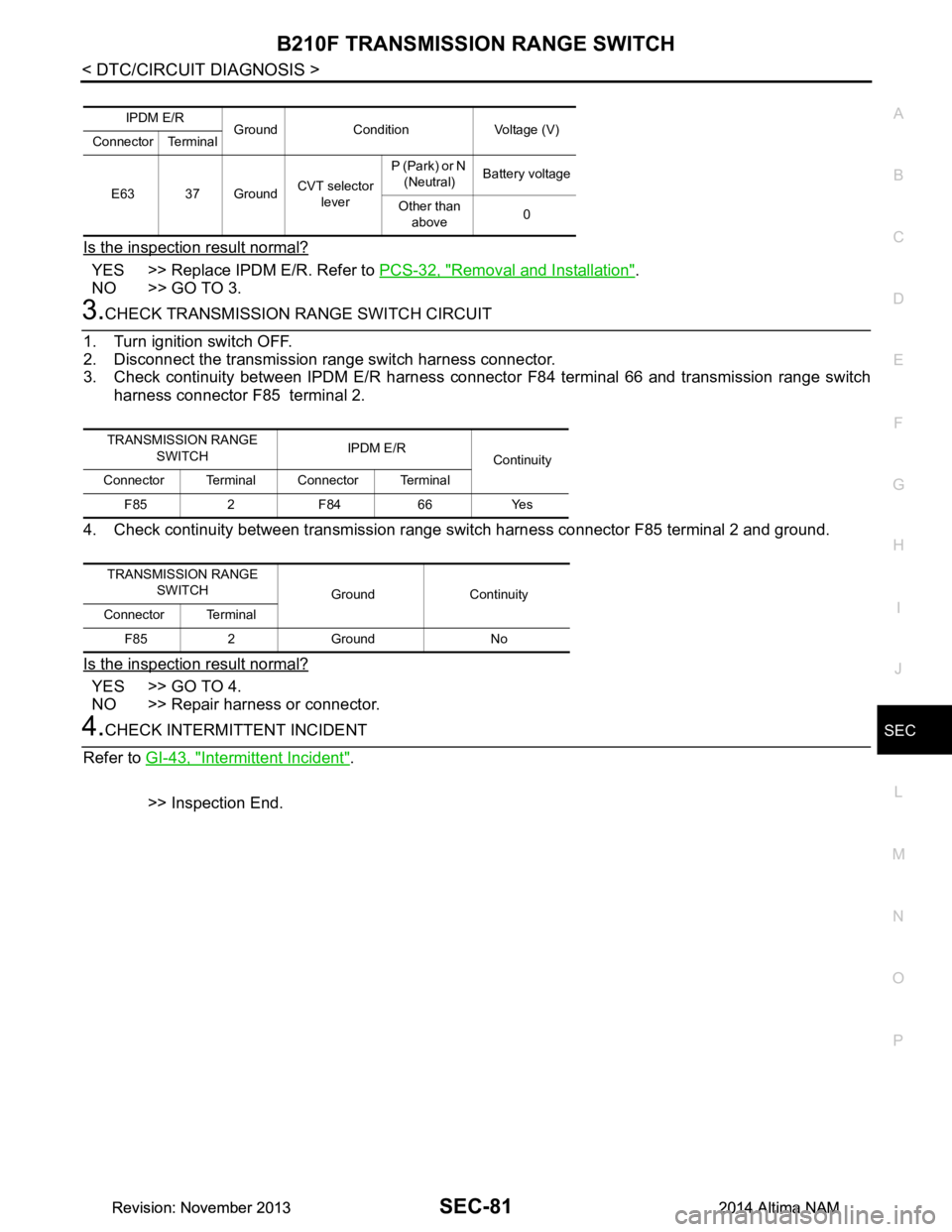
Is the inspection result normal?
YES >> Replace IPDM E/R. Refer to PCS-32, "Removal and Installation".
NO >> GO TO 3.
3.CHECK TRANSMISSION RANGE SWITCH CIRCUIT
1. Turn ignition switch OFF.
2. Disconnect the transmission range switch harness connector.
3. Check continuity between IPDM E/R harness connec tor F84 terminal 66 and transmission range switch
harness connector F85 terminal 2.
4. Check continuity between transmission range s witch harness connector F85 terminal 2 and ground.
Is the inspection result normal?
YES >> GO TO 4.
NO >> Repair harness or connector.
4.CHECK INTERMITTENT INCIDENT
Refer to GI-43, "Intermittent Incident"
.
>> Inspection End.
IPDM E/R Ground Condition Voltage (V)
Connector Terminal
E63 37 Ground CVT selector
lever P (Park) or N
(Neutral) Battery voltage
Other than above 0
TRANSMISSION RANGE
SWITCH IPDM E/R
Continuity
Connector Terminal Connector Terminal
F85 2 F84 66 Yes
TRANSMISSION RANGE SWITCH Ground Continuity
Connector Terminal
F85 2 Ground No
Revision: November 20132014 Altima NAMRevision: November 20132014 Altima NAM
Page 3908 of 4801

B2110 TRANSMISSION RANGE SWITCHSEC-83
< DTC/CIRCUIT DIAGNOSIS >
C
D E
F
G H
I
J
L
M A
B
SEC
N
O P
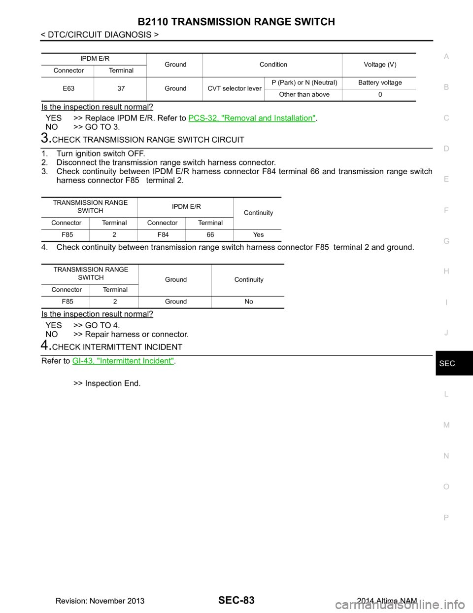
Is the inspection result normal?
YES >> Replace IPDM E/R. Refer to PCS-32, "Removal and Installation".
NO >> GO TO 3.
3.CHECK TRANSMISSION RANGE SWITCH CIRCUIT
1. Turn ignition switch OFF.
2. Disconnect the transmission range switch harness connector.
3. Check continuity between IPDM E/R harness connec tor F84 terminal 66 and transmission range switch
harness connector F85 terminal 2.
4. Check continuity between transmission range s witch harness connector F85 terminal 2 and ground.
Is the inspection result normal?
YES >> GO TO 4.
NO >> Repair harness or connector.
4.CHECK INTERMITTENT INCIDENT
Refer to GI-43, "Intermittent Incident"
.
>> Inspection End.
IPDM E/R Ground Condition Voltage (V)
Connector Terminal
E63 37 Ground CVT selector lever P (Park) or N (Neutral) Battery voltage
Other than above 0
TRANSMISSION RANGE SWITCH IPDM E/R
Continuity
Connector Terminal Connector Terminal
F85 2 F84 66 Yes
TRANSMISSION RANGE SWITCH Ground Continuity
Connector Terminal
F85 2 Ground No
Revision: November 20132014 Altima NAMRevision: November 20132014 Altima NAM
Page 3919 of 4801

SEC-94
< DTC/CIRCUIT DIAGNOSIS >
B2555 STOP LAMP
B2555 STOP LAMP
DTC LogicINFOID:0000000009461150
DTC DETECTION LOGIC
DTC CONFIRMATION PROCEDURE
1.PERFORM DTC CONFIRMATION PROCEDURE
1. Depress the brake pedal and wait 1 second or more.
2. Check DTC in “Self-Diagnostic Result” mode of “BCM” using CONSULT.
Is DTC detected?
YES >> Go to SEC-94, "Diagnosis Procedure".
NO >> Inspection End.
Diagnosis ProcedureINFOID:0000000009461151
Regarding Wiring Diagram information, refer to SEC-29, "Wiring Diagram".
1. CHECK STOP LAMP SWITCH INPUT SIGNAL
1. Turn ignition switch OFF.
2. Disconnect BCM connector M17.
3. Check voltage between BCM harness connector and ground.
Is the inspection result normal?
YES >> GO TO 8.
NO >> GO TO 2.
2. CHECK POWER SOURCE (STOP LAMP SWITCH)
1. Disconnect stop lamp switch connector.
2. Check voltage between stop lamp switch connector E38 terminal 1 and ground.
Is the inspection result normal?
YES >> GO TO 3.
NO >> Check the following: • Harness for short or open between fuse block (J/B) and stop lamp switch
• 10A fuse (No. 10, located in fuse block [J/B])
3.CHECK STOP LAMP SWITCH
DTC No. Trouble diagnosis name DTC detecting condition Possible cause
B2555 STOP LAMP BCM makes a comparison between the
upper voltage and lower voltage of stop
lamp switch. It judges from their values to
detect the malfunctioning circuit. • Harness or connectors
(Stop lamp switch circuit is open or
shorted.)
• Stop lamp switch
•Fuse
•BCM
(+) (-) Condition Voltage (V)
BCM
Connector Terminal Ground Brake pedal Depressed Battery voltage
M17 27 Not depressed 0
Stop lamp switch GroundVoltage
Connector Terminal
E38 1 Battery voltage
Revision: November 20132014 Altima NAMRevision: November 20132014 Altima NAM