2014 NISSAN TEANA battery
[x] Cancel search: batteryPage 3799 of 4801
SE-50
< UNIT DISASSEMBLY AND ASSEMBLY >
FRONT SEAT
Assembly
Assembly is in the reverse order of disassembly.
CAUTION:
• Smooth out all wrin kles during assembly.
• Always route side air bag module harness in original location. Replace any deformed or damaged
clips with same type and color. Always install clips in the original location in the harness.
• After work is completed, check that no system ma lfunction is detected causing the air bag warning
lamp to illuminate.
• If a malfunction is detected by the air bag warnin g lamp after repair or replacement of the malfunc-
tion parts, perform the SRS final check. Refer to SRC-17, "SRS Final Check"
.
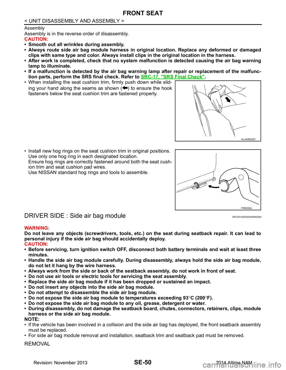
• When installing the seat cushion trim, firmly push down while slid-
ing your hand along the seams as shown ( ) to ensure the hook
fasteners below the seat cushion trim are fastened properly.
• Install new hog rings on the seat cushion trim in original positions. Use only one hog ring in each designated location.
Ensure hog rings are correctly fastened around both the seat cush-
ion trim and seat cushion pad wires.
Use NISSAN standard hog rings and tools to assemble.
DRIVER SIDE : Side air bag moduleINFOID:0000000009462950
WARNING:
Do not leave any objects (screwdrivers, tools, etc. ) on the seat during seatback repair. It can lead to
personal injury if the side ai r bag should accidentally deploy.
CAUTION:
• Before servicing, turn ignition sw itch OFF, disconnect both battery terminals and wait at least three
minutes.
• Handle the side air bag module carefully. During disassembly, alw ays hold the side air bag module,
do not let it hang by the wire harness.
• Always work from the side or back of the seat back assembly, do not work in front of seat.
• Do not use air tools or electric tools for servicing the seat assembly.
• Replace the side air bag module if it h as been dropped or sustained an impact.
• Do not insert any objects into the side air bag module.
• Do not attempt to disassemble the side air bag module.
• Do not expose the side air bag module to temperatures exceeding 93 °C (200 °F).
• Do not expose the side air bag module to any oil, grease, detergent or water.
• During disassembly, do not damage the seatback board, chutes, connectors, retainers, clips, module
harness or the side air bag module.
NOTE:
• If the vehicle has been involved in a collision and the side air bag has deployed, the front seatback assembly
must be replaced.
• For side air bag module removal and installation, seatback trim and seatback pad must be removed.
REMOVAL
ALJIA0656ZZ
PIIB3356J
Revision: November 20132014 Altima NAMRevision: November 20132014 Altima NAM
Page 3804 of 4801
FRONT SEATSE-55
< UNIT DISASSEMBLY AND ASSEMBLY >
C
D E
F
G H
I
K L
M A
B
SE
N
O P
PASSENGER SIDE : Disassembly and AssemblyINFOID:0000000009462952
SEATBACK ASSEMBLY
WARNING:
Do not leave any objects (screwdri vers, tools, etc.) on the seat during seatback repair. It can lead to
personal injury if the side air bag should accidentally deploy.
CAUTION:
• Before servicing, turn ignition swit ch OFF, disconnect both battery terminals and wait at least three
minutes.
• Handle the side air bag module carefully. During disassembly, always hold the side air bag module,
do not let it hang by the wire harness.
• Always work from the side or back of the seat back assembly, do not work in front of seat.
• Do not use air tools or electric tools for servicing the seat assembly.
• Replace the side air bag module if it h as been dropped or sustained an impact.
• Do not insert any objects into the side air bag module.
• Do not attempt to disassemble the side air bag module.
• Do not expose the side air bag module to temperatures exceeding 93 °C (200 °F).
• Do not expose the side air bag module to any oil, grease, detergent or water.
• During disassembly, do not damage the seatback board , chutes, connectors, retainers, clips, module
harness or the side air bag module.
NOTE:
If the vehicle has been involved in a collision and the side air bag has deployed, the front seatback assembly
must be replaced.
Disassembly
1. Remove the front seat assembly. Refer to SE-30, "PASSENGER SIDE : Removal and Installation - Seat
Assembly".
2. Remove the seatback board. Refer to SE-31, "PASSENGER SIDE : Removal and Installation - Seatback
Board".
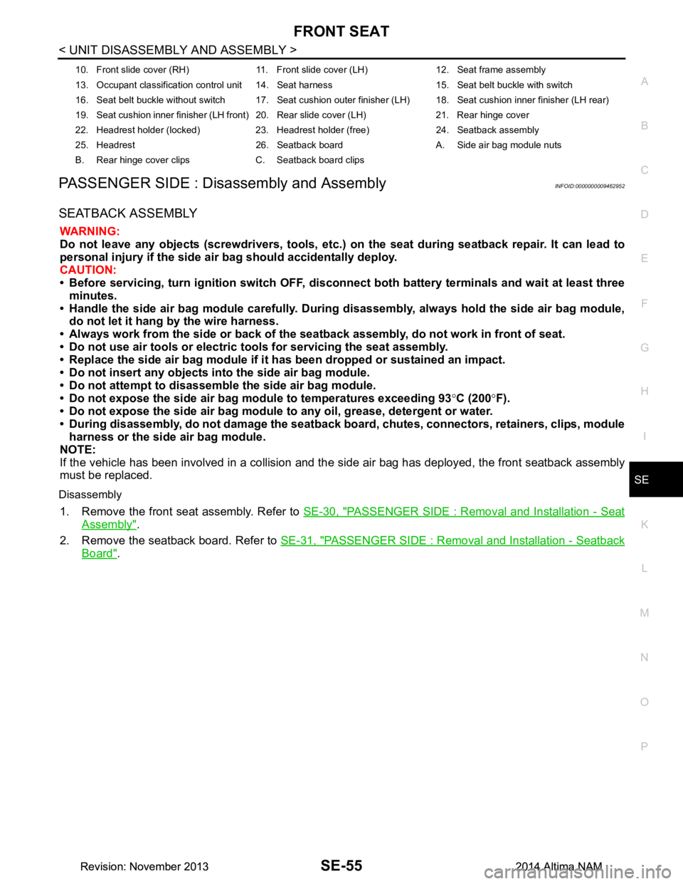
10. Front slide cover (RH) 11. Front slide cover (LH) 12. Seat frame assembly
13. Occupant classification control unit 14. Seat harness 15. Seat belt buckle with switch
16. Seat belt buckle without switch 17. Seat cushion outer finisher (LH) 18. Seat cushion inner finisher (LH rear)
19. Seat cushion inner finisher (LH front) 20. Rear slide cover (LH) 21. Rear hinge cover
22. Headrest holder (locked) 23. Headrest holder (free) 24. Seatback assembly
25. Headrest 26. Seatback board A. Side air bag module nuts
B. Rear hinge cover clips C. Seatback board clips
Revision: November 20132014 Altima NAMRevision: November 20132014 Altima NAM
Page 3808 of 4801
FRONT SEATSE-59
< UNIT DISASSEMBLY AND ASSEMBLY >
C
D E
F
G H
I
K L
M A
B
SE
N
O P
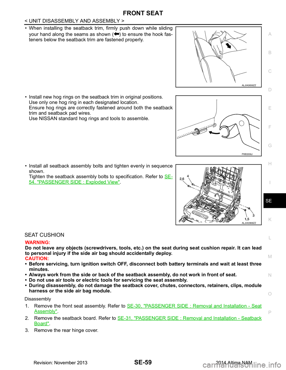
• When installing the seatback trim, firmly push down while sliding your hand along the seams as shown ( ) to ensure the hook fas-
teners below the seatback trim are fastened properly.
• Install new hog rings on the seatback trim in original positions. Use only one hog ring in each designated location.
Ensure hog rings are correctly fastened around both the seatback
trim and seatback pad wires.
Use NISSAN standard hog rings and tools to assemble.
• Install all seatback assembly bolts and tighten evenly in sequence shown.
Tighten the seatback assembly bolts to specification. Refer to SE-
54, "PASSENGER SIDE : Exploded View".
SEAT CUSHION
WARNING:
Do not leave any objects (screwdrivers, tools, etc. ) on the seat during seat cushion repair. It can lead
to personal injury if the side air bag should accidentally deploy.
CAUTION:
• Before servicing, turn ignition swit ch OFF, disconnect both battery terminals and wait at least three
minutes.
• Always work from the side or back of the seat back assembly, do not work in front of seat.
• Do not use air tools or electric tools for servicing the seat assembly.
• During disassembly, do not damage the seatback cover , chutes, connectors, retainers, clips, module
harness or the side air bag module.
Disassembly
1. Remove the front seat assembly. Refer to SE-30, "PASSENGER SIDE : Removal and Installation - Seat
Assembly".
2. Remove the seatback board. Refer to SE-31, "PASSENGER SIDE : Removal and Installation - Seatback
Board".
3. Remove the rear hinge cover.
ALJIA0656ZZ
PIIB3356J
ALJIA0968ZZ
Revision: November 20132014 Altima NAMRevision: November 20132014 Altima NAM
Page 3811 of 4801
SE-62
< UNIT DISASSEMBLY AND ASSEMBLY >
FRONT SEAT
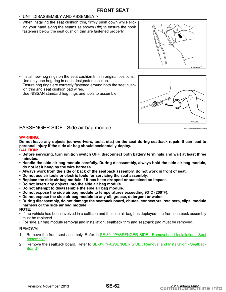
• When installing the seat cushion trim, firmly push down while slid-ing your hand along the seams as shown ( ) to ensure the hook
fasteners below the seat cushion trim are fastened properly.
• Install new hog rings on the seat cushion trim in original positions. Use only one hog ring in each designated location.
Ensure hog rings are correctly fastened around both the seat cush-
ion trim and seat cushion pad wires.
Use NISSAN standard hog rings and tools to assemble.
PASSENGER SIDE : Side air bag moduleINFOID:0000000009462953
WARNING:
Do not leave any objects (screwdrivers, tools, etc. ) on the seat during seatback repair. It can lead to
personal injury if the side ai r bag should accidentally deploy.
CAUTION:
• Before servicing, turn ignition sw itch OFF, disconnect both battery terminals and wait at least three
minutes.
• Handle the side air bag module carefully. During disassembly, alw ays hold the side air bag module,
do not let it hang by the wire harness.
• Always work from the side or back of the seat back assembly, do not work in front of seat.
• Do not use air tools or electric tools for servicing the seat assembly.
• Replace the side air bag module if it h as been dropped or sustained an impact.
• Do not insert any objects into the side air bag module.
• Do not attempt to disassemble the side air bag module.
• Do not expose the side air bag module to temperatures exceeding 93 °C (200 °F).
• Do not expose the side air bag module to any oil, grease, detergent or water.
• During disassembly, do not damage the seatback board, chutes, connectors, retainers, clips, module
harness or the side air bag module.
NOTE:
• If the vehicle has been involved in a collision and the side air bag has deployed, the front seatback assembly
must be replaced.
• For side air bag module removal and installation, seatback trim and seatback pad must be removed.
REMOVAL
1. Remove the front seat assembly. Refer to SE-30, "PASSENGER SIDE : Removal and Installation - Seat
Assembly".
2. Remove the seatback board. Refer to SE-31, "PASSENGER SIDE : Removal and Installation - Seatback
Board".
ALJIA0656ZZ
PIIB3356J
Revision: November 20132014 Altima NAMRevision: November 20132014 Altima NAM
Page 3829 of 4801
SEC-4
< PRECAUTION >
PRECAUTIONS
PRECAUTION
PRECAUTIONS
Precaution for Supplemental Restraint System (SRS) "AIR BAG" and "SEAT BELT
PRE-TENSIONER"
INFOID:0000000009951563
The Supplemental Restraint System such as “A IR BAG” and “SEAT BELT PRE-TENSIONER”, used along
with a front seat belt, helps to reduce the risk or severi ty of injury to the driver and front passenger for certain
types of collision. Information necessary to service the system safely is included in the SR and SB section of
this Service Manual.
WARNING:
• To avoid rendering the SRS inopera tive, which could increase the risk of personal injury or death in
the event of a collision which would result in air bag inflation, all maintenance must be performed by
an authorized NISS AN/INFINITI dealer.
• Improper maintenance, including in correct removal and installation of the SRS, can lead to personal
injury caused by unintent ional activation of the system. For re moval of Spiral Cable and Air Bag
Module, see the SR section.
• Do not use electrical test equipmen t on any circuit related to the SRS unless instructed to in this
Service Manual. SRS wiring harn esses can be identified by yellow and/or orange harnesses or har-
ness connectors.
PRECAUTIONS WHEN USING POWER TOOLS (AIR OR ELECTRIC) AND HAMMERS
WARNING:
• When working near the Airbag Diagnosis Sensor Unit or other Airbag System sensors with the Igni-
tion ON or engine running, DO NOT use air or electri c power tools or strike near the sensor(s) with a
hammer. Heavy vibration could activate the sensor( s) and deploy the air bag(s), possibly causing
serious injury.
• When using air or electric power tools or hammers , always switch the Ignition OFF, disconnect the
battery and wait at least three minutes before performing any service.
Precaution for WorkINFOID:0000000009461062
• When removing or disassembling each component, be careful not to damage or deform it. If a component may be subject to interference, be sure to protect it with a shop cloth.
• When removing (disengaging) components with a screwdriver or similar tool, be sure to wrap the component with a shop cloth or vinyl tape to protect it.
• Protect the removed parts with a s hop cloth and prevent them from being dropped.
• Replace a deformed or damaged clip.
• If a part is specified as a non-reusable part, always replace it with a new one.
• Be sure to tighten bolts and nuts securely to the specified torque.
• After installation is complete, be sure to check that each part works properly.
• Follow the steps below to clean components:
- Water soluble dirt:
• Dip a soft cloth into lukewarm water, wring the water out of the cloth and wipe the dirty area.
• Then rub with a soft, dry cloth.
- Oily dirt:
• Dip a soft cloth into lukewarm water with mild detergent (concentration: within 2 to 3%) and wipe the dirty area.
• Then dip a cloth into fresh water, wring the water out of the cloth and wipe the detergent off.
• Then rub with a soft, dry cloth.
- Do not use organic solvent such as thinner, benzene, alcohol or gasoline.
- For genuine leather seats, use a genuine leather seat cleaner.
Revision: November 20132014 Altima NAMRevision: November 20132014 Altima NAM
Page 3834 of 4801

COMPONENT PARTSSEC-9
< SYSTEM DESCRIPTION >
C
D E
F
G H
I
J
L
M A
B
SEC
N
O P
If the verification result is OK, the engine can start. If the verification result is NG, the engine can not start.
IPDM E/RINFOID:0000000009461069
IPDM E/R has the starter relay and starter control relay inside. Starter relay and starter control relay are used
for the engine starting function. IPDM E/R contro ls these relays while communicating with BCM.
NATS Antenna Amp.INFOID:0000000009461070
The ID verification is performed between BCM and transponder in Intelligent Key via NATS antenna amp.
when Intelligent Key backside is contacted to push-button i gnition switch in case that Intelligent Key battery is
discharged. If the ID verification result is OK, the operation of starting engine is available.
TCMINFOID:0000000009461071
TCM transmits the shift position signal (P/N position) to BCM and IPDM E/R. And further, TCM transmits the
shift position signal (P/N position) to BCM via CAN communication.
BCM confirms the CVT shift selector position with the following 5 signals:
• P (Park) position signal from CVT shift selector (park position switch)
• P/N position signal from TCM
• P (Park) position signal from IPDM E/R (CAN)
• P/N position signal from IPDM E/R (CAN)
• P/N position signal from TCM (CAN)
IPDM E/R confirms the CVT shift select or position with the following 3 signals:
• P (Park) position signal from CVT shift selector (park position switch)
• P/N position signal from TCM
• P/N position signal from BCM (CAN)
Combination MeterINFOID:0000000009461072
Combination meter transmits the vehicle speed signal to BCM via CAN communication.
BCM also receives the vehicle speed signal from ABS ac tuator and electric unit (control unit) via CAN commu-
nication. BCM compares both signals to detect the vehicle speed.
Door SwitchINFOID:0000000009461073
Door switch detects door open/close conditi on and then transmits ON/OFF signal to BCM.
Outside Key AntennaINFOID:0000000009461074
Outside key antenna detects whether Intelligent Key is outside the vehicle and transmits the signal to BCM.
Three outside key antennas are installed in the front outside handle LH, front outside handle RH and rear
bumper.
Hood SwitchINFOID:0000000009461075
Hood switch detects that hood is open/closed, and then trans mits the signal to IPDM E/R. IPDM E/R transmits
hood switch signal to BCM via CAN communication.
Inside Key AntennaINFOID:0000000009461076
Inside key antenna detects whether Intelligent Key is inside the vehicle and transmits the signal to BCM.
Two inside key antennas are installed in the front console and rear parcel shelf.
Remote Keyless Entry ReceiverINFOID:0000000009461077
Remote keyless entry receiver receives each button oper ation signal and electronic key ID signal from Intelli-
gent Key and then transmits the signal to BCM.
Intelligent KeyINFOID:0000000009461078
Each Intelligent Key has an individual electronic ID and transmits the ID signal by request from BCM.
Carrying the Intelligent Key whose ID is registered in BCM, the driver can perform, remote start, door lock/
unlock operation, remote trunk, panic alarm and push-button ignition switch operation.
Revision: November 20132014 Altima NAMRevision: November 20132014 Altima NAM
Page 3836 of 4801
SYSTEMSEC-11
< SYSTEM DESCRIPTION >
C
D E
F
G H
I
J
L
M A
B
SEC
N
O P
SYSTEM
INTELLIGENT KEY SYSTEM/ ENGINE START FUNCTION
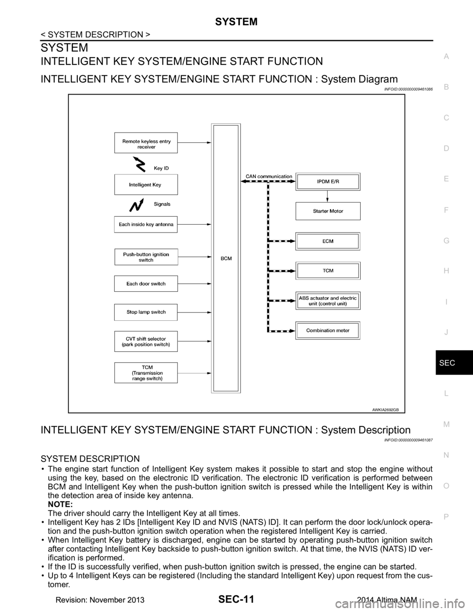
INTELLIGENT KEY SYSTEM/ENGINE ST ART FUNCTION : System Diagram
INFOID:0000000009461086
INTELLIGENT KEY SYSTEM/ENGINE STAR T FUNCTION : System Description
INFOID:0000000009461087
SYSTEM DESCRIPTION
• The engine start function of Intelligent Key system makes it possible to start and stop the engine without
using the key, based on the electronic ID verification. The electronic ID verification is performed between
BCM and Intelligent Key when the push-button ignition switch is pressed while the Intelligent Key is within
the detection area of inside key antenna.
NOTE:
The driver should carry the Intelligent Key at all times.
• Intelligent Key has 2 IDs [Intelligent Key ID and NVIS (NATS) ID]. It can perform the door lock/unlock opera-
tion and the push-button ignition switch operation when the registered Intelligent Key is carried.
• When Intelligent Key battery is discharged, engine c an be started by operating push-button ignition switch
after contacting Intelligent Key backside to push-button i gnition switch. At that time, the NVIS (NATS) ID ver-
ification is performed.
• If the ID is successfully verified, when push-button ignition switch is pressed, the engine can be started.
• Up to 4 Intelligent Keys can be registered (Includi ng the standard Intelligent Key) upon request from the cus-
tomer.
AWKIA2692GB
Revision: November 20132014 Altima NAMRevision: November 20132014 Altima NAM
Page 3837 of 4801
SEC-12
< SYSTEM DESCRIPTION >
SYSTEM
NOTE:
Refer to DLK-23, "INTELLIGENT KEY SYSTEM : System Description"
for any functions other than engine
start function of Intelligent Key system.
PRECAUTIONS FOR INTELLIGENT KEY SYSTEM
The transponder [the chip for NVIS (NATS) ID verifi cation] is integrated into the Intelligent Key.
In that case, the NVIS (NATS) ID verification can be performed when Intelligent Key backside is con-
tacted to push-button ignition switch. If verification result is OK, engine can be started.
OPERATION WHEN INTELLIGENT KEY IS CARRIED
1. When the push-button ignition switch is pressed, the BCM activates the inside key antenna and transmits
the request signal to the Intelligent Key.
2. The Intelligent Key receives the request signal and transmits the Intelligent Key ID signal to the BCM.
3. BCM receives the Intelligent Key ID signal via remote keyless entry receiver and verifies it with the regis-
tered ID.
4. BCM turns ACC relay ON and transmits the ignition power supply ON signal to IPDM E/R.
5. IPDM E/R turns the ignition relay ON and starts the ignition power supply.
6. BCM detects that the selector leve r position and brake pedal operating condition.
7. BCM transmits the starter request signal to IPDM E/R and turns the starter relay in IPDM E/R ON if BCM judges that the engine start condition* is satisfied.
8. IPDM E/R turns the starter control relay ON when receiving the starter request signal.
9. Power supply is supplied through the starter relay and the starter control relay to operate the starter motor. CAUTION:
If a malfunction is detected in the Intelligent Key system, the “KEY” warning lamp in the combina-
tion meter illuminates. At that ti me, the engine cannot be started.
10. When BCM receives feedback signal from ECM indicati ng that the engine is started, the BCM transmits a
stop signal to IPDM E/R and stops cranking by turning OFF the starter motor relay. (If engine start is
unsuccessful, cranking stops autom atically within 5 seconds.)
CAUTION:
When the Intelligent Key is carri ed outside of the vehicle (inside key antenna detection area) while
the power supply is in the ACC or ON position, even if the engine start condition* is satisfied, the
engine cannot be started.
*: For the engine start condition, refer to the tabl e below “POWER SUPPLY POSITION CHANGE TABLE BY
PUSH-BUTTON IGNITION SWITCH OPERATION”.
OPERATION RANGE
Engine can be started when Intelligent Key is inside the vehicle. However, sometimes engine may not start
when Intelligent Key is on instrument panel or in glove box.
ENGINE START OPERATION WHEN INTELLIGENT KEY IS CONTACTED TO PUSH-BUTTON IG-
NITION SWITCH
When Intelligent Key battery is discharged, the NVIS (NATS) ID verification between transponder in Intelligent
Key and BCM is performed when Intelligent Key backside is contacted to push-button ignition switch. If the
verification result is OK, engine can be started.
POWER SUPPLY POSITION CHANGE TABLE BY PUSH-BUTTON IGNITION SWITCH OPERA-
TION
The power supply position changing operation c an be performed with the following operations.
NOTE:
• When an Intelligent Key is within the detection area of inside key antenna and when Intelligent Key backside
is contacted to push-button ignition switch, it is equivalent to the operations below.
• When starting the engine, the BCM monitors under the engine start conditions:
- Brake pedal operating condition
- Selector lever position
- Vehicle speed
Vehicle speed: less than 4 km/h (2.5 MPH)
Revision: November 20132014 Altima NAMRevision: November 20132014 Altima NAM