2014 NISSAN TEANA battery
[x] Cancel search: batteryPage 3744 of 4801
FRONT SEAT BELTSB-9
< REMOVAL AND INSTALLATION >
C
D E
F
G
I
J
K L
M A
B
SB
N
O P
2. Disconnect both negative and positive battery terminals, then wait at least three minutes. Refer to PG-73,
"Removal and Installation (Battery)".
3. Remove center pillar lower finisher. Refer to INT-23, "CENTER PILLAR LOWER FINISHER : Removal
and Installation".
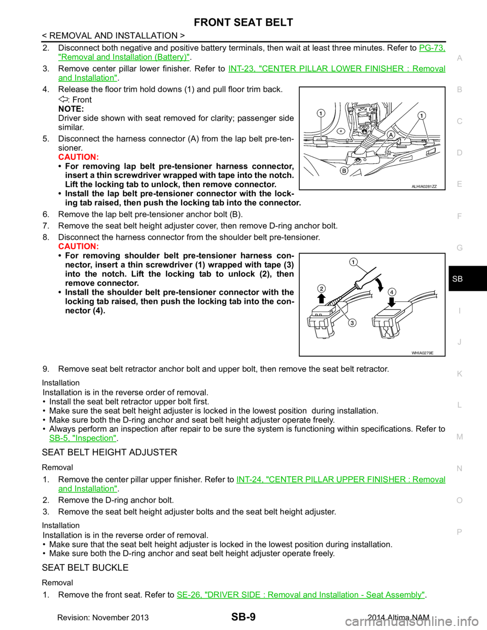
4. Release the floor trim hold downs (1) and pull floor trim back. : Front
NOTE:
Driver side shown with seat removed for clarity; passenger side
similar.
5. Disconnect the harness connector (A ) from the lap belt pre-ten-
sioner.
CAUTION:
• For removing lap belt pre-tensioner harness connector, insert a thin screwdriver wrappe d with tape into the notch.
Lift the locking tab to un lock, then remove connector.
• Install the lap belt pre-tensioner connector with the lock- ing tab raised, then push the locking tab into the connector.
6. Remove the lap belt pre-tensioner anchor bolt (B).
7. Remove the seat belt height adjuster cover, then remove D-ring anchor bolt.
8. Disconnect the harness connector from the shoulder belt pre-tensioner. CAUTION:
• For removing shoulder belt pre-tensioner harness con- nector, insert a thin screwdriver (1) wrapped with tape (3)
into the notch. Lift the lo cking tab to unlock (2), then
remove connector.
• Install the shoulder belt pr e-tensioner connector with the
locking tab raised, then push the locking tab into the con-
nector (4).
9. Remove seat belt retractor anchor bolt and upper bolt, then remove the seat belt retractor.
Installation
Installation is in the reverse order of removal.
• Install the seat belt retractor upper bolt first.
• Make sure the seat belt height adjuster is lock ed in the lowest position during installation.
• Make sure both the D-ring anchor and seat belt height adjuster operate freely.
• Always perform an inspection after repair to be sure t he system is functioning within specifications. Refer to
SB-5, "Inspection"
.
SEAT BELT HEIGHT ADJUSTER
Removal
1. Remove the center pillar upper finisher. Refer to INT-24, "CENTER PILLAR UPPER FINISHER : Removal
and Installation".
2. Remove the D-ring anchor bolt.
3. Remove the seat belt height adjuster bolts and the seat belt height adjuster.
Installation
Installation is in the reverse order of removal.
• Make sure that the seat belt height adjuster is locked in the lowest position during installation.
• Make sure both the D-ring anchor and seat belt height adjuster operate freely.
SEAT BELT BUCKLE
Removal
1. Remove the front seat. Refer to SE-26, "DRIVER SIDE : Removal and Installation - Seat Assembly".
ALHIA0281ZZ
WHIA0279E
Revision: November 20132014 Altima NAM
Page 3751 of 4801
SE-2
< PRECAUTION >
PRECAUTIONS
PRECAUTION
PRECAUTIONS
Precaution for Supplemental Restraint System (SRS) "AIR BAG" and "SEAT BELT
PRE-TENSIONER"
INFOID:0000000009951559
The Supplemental Restraint System such as “A IR BAG” and “SEAT BELT PRE-TENSIONER”, used along
with a front seat belt, helps to reduce the risk or severi ty of injury to the driver and front passenger for certain
types of collision. Information necessary to service the system safely is included in the SR and SB section of
this Service Manual.
WARNING:
• To avoid rendering the SRS inopera tive, which could increase the risk of personal injury or death in
the event of a collision which would result in air bag inflation, all maintenance must be performed by
an authorized NISS AN/INFINITI dealer.
• Improper maintenance, including in correct removal and installation of the SRS, can lead to personal
injury caused by unintent ional activation of the system. For re moval of Spiral Cable and Air Bag
Module, see the SR section.
• Do not use electrical test equipmen t on any circuit related to the SRS unless instructed to in this
Service Manual. SRS wiring harn esses can be identified by yellow and/or orange harnesses or har-
ness connectors.
PRECAUTIONS WHEN USING POWER TOOLS (AIR OR ELECTRIC) AND HAMMERS
WARNING:
• When working near the Airbag Diagnosis Sensor Unit or other Airbag System sensors with the Igni-
tion ON or engine running, DO NOT use air or electri c power tools or strike near the sensor(s) with a
hammer. Heavy vibration could activate the sensor( s) and deploy the air bag(s), possibly causing
serious injury.
• When using air or electric power tools or hammers , always switch the Ignition OFF, disconnect the
battery and wait at least three minutes before performing any service.
Precaution for WorkINFOID:0000000009462924
• When removing or disassembling each component, be careful not to damage or deform it. If a component may be subject to interference, be sure to protect it with a shop cloth.
• When removing (disengaging) components with a screwdriver or similar tool, be sure to wrap the component with a shop cloth or vinyl tape to protect it.
• Protect the removed parts with a s hop cloth and prevent them from being dropped.
• Replace a deformed or damaged clip.
• If a part is specified as a non-reusable part, always replace it with a new one.
• Be sure to tighten bolts and nuts securely to the specified torque.
• After installation is complete, be sure to check that each part works properly.
• Follow the steps below to clean components:
- Water soluble dirt:
• Dip a soft cloth into lukewarm water, wring the water out of the cloth and wipe the dirty area.
• Then rub with a soft, dry cloth.
- Oily dirt:
• Dip a soft cloth into lukewarm water with mild detergent (concentration: within 2 to 3%) and wipe the dirty area.
• Then dip a cloth into fresh water, wring the water out of the cloth and wipe the detergent off.
• Then rub with a soft, dry cloth.
- Do not use organic solvent such as thinner, benzene, alcohol or gasoline.
- For genuine leather seats, use a genuine leather seat cleaner.
Revision: November 20132014 Altima NAMRevision: November 20132014 Altima NAM
Page 3775 of 4801
SE-26
< REMOVAL AND INSTALLATION >
FRONT SEAT
DRIVER SIDE : Removal and In stallation - Seat Assembly
INFOID:0000000009462934
REMOVAL
WARNING:
Do not leave any objects (screwdriver s, tools, etc.) on the seat during seat repair. It can lead to per-
sonal injury if the side air bag module should accidentally deploy.
CAUTION:
• When removing or installing the seat trim, handle it carefully to keep dirt out and to avoid damage.
• When checking the power seat circuit for continuity using a circuit tester, do not confuse its connec-
tor with the side air bag module connector. Such an error may cau se the air bag module to deploy.
• Do not drop, tilt, or bump the si de air bag module while installing the seat. Always handle it with
care.
• After front side air bag module inflates, the front seatback assembly must be replaced.
• When removing and installing the seat, use shop cloths to protect components from damage.
• Before removing the front seat, turn the ignition switch OFF, disconnect both battery cables and wait
at least three minutes.
1. Remove the headrest.
2. Raise seat to the highest position.
3. Slide the seat to the full rearward position.
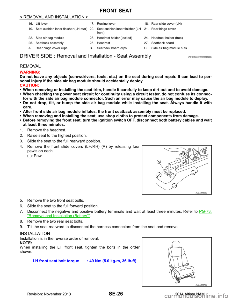
4. Remove the front slide covers (LH/RH) (A) by releasing four pawls on each.
: Pawl
5. Remove the two front seat bolts.
6. Slide the seat to the full forward position.
7. Disconnect the negative and positive battery terminal s and wait at least three minutes. Refer to PG-73,
"Removal and Installation (Battery)".
8. Remove the two rear seat bolts.
9. Tilt the seat rearward to disconnect the harness connectors from the seat and remove.
INSTALLATION
Installation is in the reverse order of removal.
NOTE:
When installing the LH front seat , tighten the bolts in the order
shown.
16. Lift lever 17. Recline lever 18. Rear slide cover (LH)
19. Seat cushion inner finisher (LH rear) 20. Seat cushion inner finisher (LH front)21. Rear hinge cover
22. Side air bag module 23. Headrest holder (locked) 24. Headrest holder (free)
25. Seatback assembly 26. Headrest 27. Seatback board
A. Rear hinge cover clips B. Seatback board clips C. Side air bag module nuts
ALJIA0929ZZ
LH front seat bolt torque : 49 Nm (5.0 kg-m, 36 lb-ft)
ALJIA0927ZZ
Revision: November 20132014 Altima NAMRevision: November 20132014 Altima NAM
Page 3776 of 4801
FRONT SEATSE-27
< REMOVAL AND INSTALLATION >
C
D E
F
G H
I
K L
M A
B
SE
N
O P
CAUTION:
Make sure that the seat harness or the floor trim is not damaged during installation.
DRIVER SIDE : Removal and Installation - Seatback BoardINFOID:0000000009462935
REMOVAL
CAUTION:
• Before servicing, turn ignition swit ch OFF, disconnect both battery terminals and wait at least three
minutes.
• Always work from the side or back of the seat back assembly, do not work in front of seat.
1. Slide the seat to the full forward position.
2. Disconnect the negative and positive battery terminal s and wait at least three minutes. Refer to PG-73,
"Removal and Installation (Battery)".
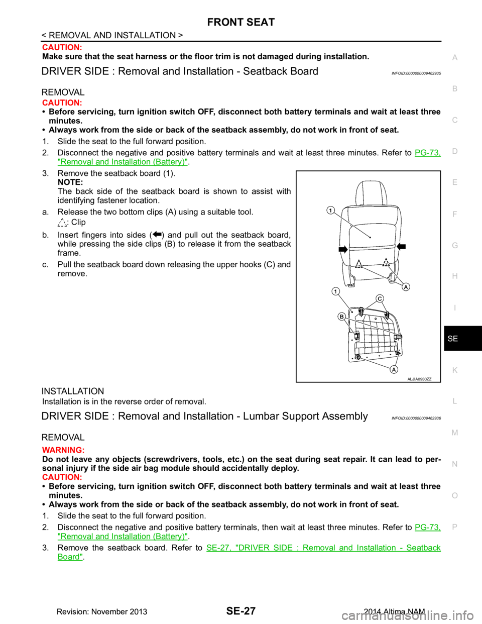
3. Remove the seatback board (1). NOTE:
The back side of the seatback boar d is shown to assist with
identifying fastener location.
a. Release the two bottom clips (A) using a suitable tool. : Clip
b. Insert fingers into sides ( ) and pull out the seatback board, while pressing the side clips (B) to release it from the seatback
frame.
c. Pull the seatback board down releasing the upper hooks (C) and remove.
INSTALLATION
Installation is in the reverse order of removal.
DRIVER SIDE : Removal and Installation - Lumbar Support AssemblyINFOID:0000000009462936
REMOVAL
WARNING:
Do not leave any objects (screwdriver s, tools, etc.) on the seat during seat repair. It can lead to per-
sonal injury if the side air bag module should accidentally deploy.
CAUTION:
• Before servicing, turn ignition swit ch OFF, disconnect both battery terminals and wait at least three
minutes.
• Always work from the side or back of the seat back assembly, do not work in front of seat.
1. Slide the seat to the full forward position.
2. Disconnect the negative and positive bat tery terminals, then wait at least three minutes. Refer to PG-73,
"Removal and Installation (Battery)".
3. Remove the seatback board. Refer to SE-27, "DRIVER SIDE : Removal and Installation - Seatback
Board".
ALJIA0930ZZ
Revision: November 20132014 Altima NAMRevision: November 20132014 Altima NAM
Page 3779 of 4801
SE-30
< REMOVAL AND INSTALLATION >
FRONT SEAT
PASSENGER SIDE : Removal and Installation - Seat Assembly
INFOID:0000000009462938
REMOVAL
WARNING:
Do not leave any objects (screwdriver s, tools, etc.) on the seat during seat repair. It can lead to per-
sonal injury if the side air bag module should accidentally deploy.
CAUTION:
• When removing or installing the seat trim, handle it carefully to keep dirt out and to avoid damage.
• When checking the power seat circuit for continuity using a circuit tester, do not confuse its connec-
tor with the side air bag module connector. Such an error may cau se the air bag module to deploy.
• Do not drop, tilt, or bump the si de air bag module while installing the seat. Always handle it with
care.
• After front side air bag module inflates, the front seatback assembly must be replaced.
• When removing and installing the seat, use shop cloths to protect components from damage.
• Before removing the front seat, turn the ignition switch OFF, disconnect both battery cables and wait
at least three minutes.
1. Disconnect the negative and positive battery terminal s and wait at least three minutes. Refer to PG-73,
"Removal and Installation (Battery)".
2. Remove the headrest.
3. Slide the seat to the full rearward position.
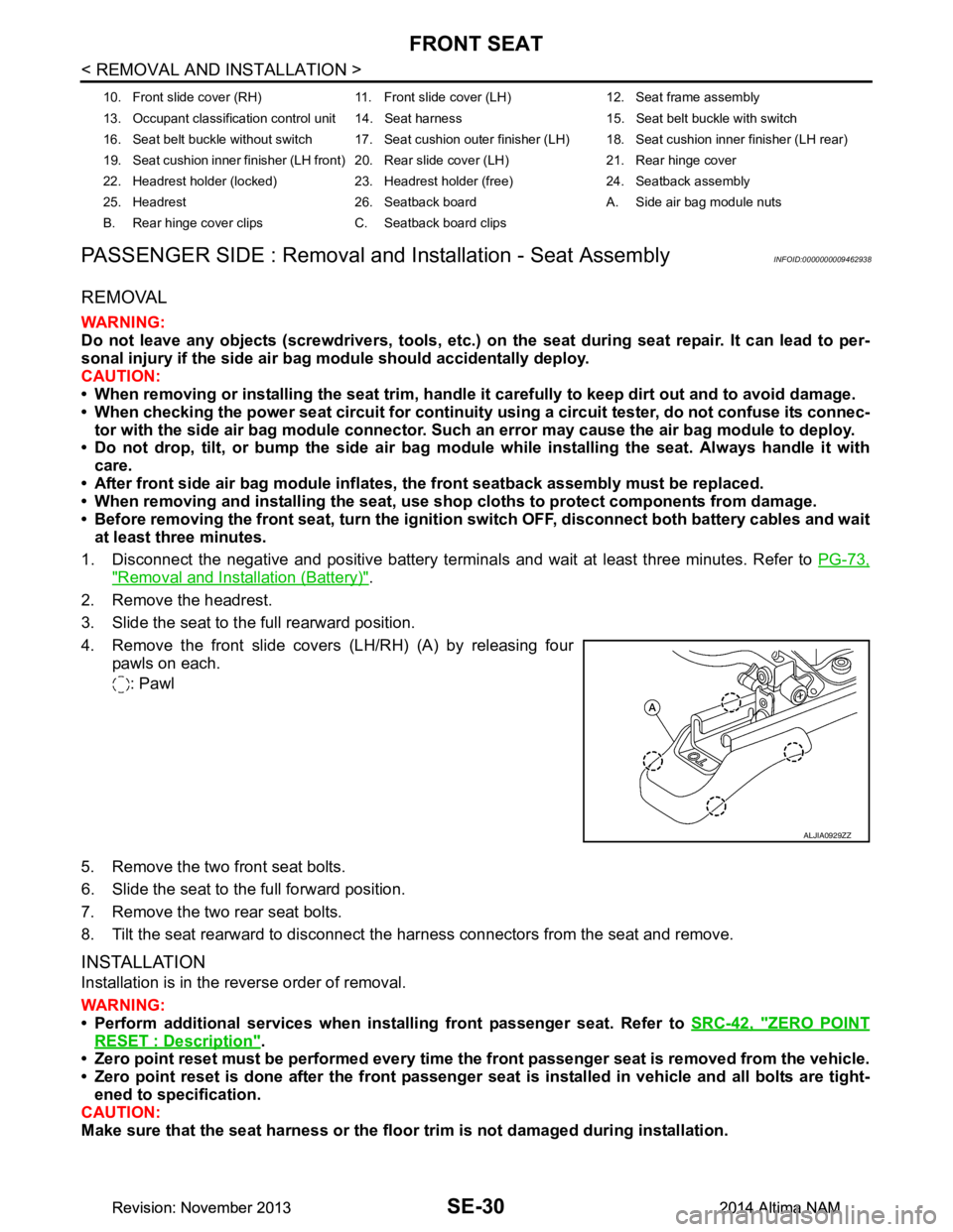
4. Remove the front slide covers (LH/RH) (A) by releasing four pawls on each.
: Pawl
5. Remove the two front seat bolts.
6. Slide the seat to the full forward position.
7. Remove the two rear seat bolts.
8. Tilt the seat rearward to disconnect the harness connectors from the seat and remove.
INSTALLATION
Installation is in the reverse order of removal.
WARNING:
• Perform additional services when instal ling front passenger seat. Refer to SRC-42, "ZERO POINT
RESET : Description".
• Zero point reset must be performed every time th e front passenger seat is removed from the vehicle.
• Zero point reset is done after the front passenger seat is installed in vehicle and all bolts are tight-
ened to specification.
CAUTION:
Make sure that the seat harness or the floor trim is not damaged during installation.
10. Front slide cover (RH) 11. Front sl ide cover (LH) 12. Seat frame assembly
13. Occupant classification control unit 14. Seat harness 15. Seat belt buckle with switch
16. Seat belt buckle without switch 17. Seat cushion outer finisher (LH) 18. Seat cushion inner finisher (LH rear)
19. Seat cushion inner finisher (LH front) 20. Rear slide cover (LH) 21. Rear hinge cover
22. Headrest holder (locked) 23. Headrest holder (free) 24. Seatback assembly
25. Headrest 26. Seatback board A. Side air bag module nuts
B. Rear hinge cover clips C. Seatback board clips
ALJIA0929ZZ
Revision: November 20132014 Altima NAMRevision: November 20132014 Altima NAM
Page 3780 of 4801
FRONT SEATSE-31
< REMOVAL AND INSTALLATION >
C
D E
F
G H
I
K L
M A
B
SE
N
O P
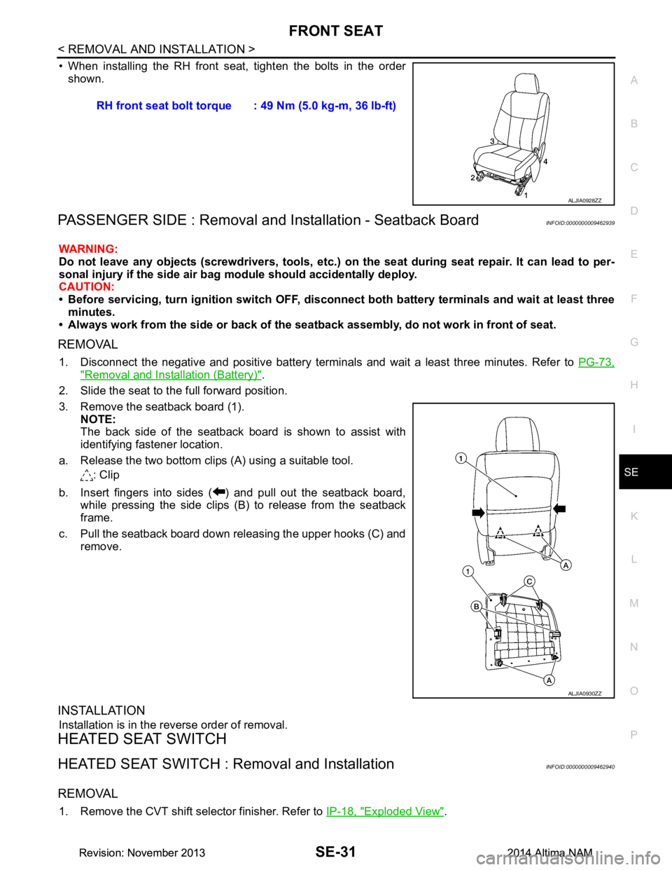
• When installing the RH front seat, tighten the bolts in the order shown.
PASSENGER SIDE : Removal and In stallation - Seatback BoardINFOID:0000000009462939
WARNING:
Do not leave any objects (screwdriver s, tools, etc.) on the seat during seat repair. It can lead to per-
sonal injury if the side air bag module should accidentally deploy.
CAUTION:
• Before servicing, turn ignition swit ch OFF, disconnect both battery terminals and wait at least three
minutes.
• Always work from the side or back of the seat back assembly, do not work in front of seat.
REMOVAL
1. Disconnect the negative and positive battery terminals and wait a least three minutes. Refer to PG-73,
"Removal and Installation (Battery)".
2. Slide the seat to the full forward position.
3. Remove the seatback board (1). NOTE:
The back side of the seatback boar d is shown to assist with
identifying fastener location.
a. Release the two bottom clips (A) using a suitable tool. : Clip
b. Insert fingers into sides ( ) and pull out the seatback board, while pressing the side clips (B) to release from the seatback
frame.
c. Pull the seatback board down releasing the upper hooks (C) and remove.
INSTALLATION
Installation is in the reverse order of removal.
HEATED SEAT SWITCH
HEATED SEAT SWITCH : Removal and InstallationINFOID:0000000009462940
REMOVAL
1. Remove the CVT shift selector finisher. Refer to IP-18, "Exploded View".
RH front seat bolt torque : 49 Nm (5.0 kg-m, 36 lb-ft)
ALJIA0928ZZ
ALJIA0930ZZ
Revision: November 20132014 Altima NAMRevision: November 20132014 Altima NAM
Page 3791 of 4801
SE-42
< UNIT DISASSEMBLY AND ASSEMBLY >
FRONT SEAT
DRIVER SIDE : Disassembly and Assembly
INFOID:0000000009462949
SEATBACK ASSEMBLY
WARNING:
Do not leave any objects (screwdrivers, tools, etc. ) on the seat during seatback repair. It can lead to
personal injury if the side ai r bag should accidentally deploy.
CAUTION:
• Before servicing, turn ignition sw itch OFF, disconnect both battery terminals and wait at least three
minutes.
• Handle the side air bag module carefully. During disassembly, alw ays hold the side air bag module,
do not let it hang by the wire harness.
• Always work from the side or back of the seat back assembly, do not work in front of seat.
• Do not use air tools or electric tools for servicing the seat assembly.
• Replace the side air bag module if it h as been dropped or sustained an impact.
• Do not insert any objects into the side air bag module.
• Do not attempt to disassemble the side air bag module.
• Do not expose the side air bag module to temperatures exceeding 93 °C (200 °F).
• Do not expose the side air bag module to any oil, grease, detergent or water.
• During disassembly, do not damage the seatback board, chutes, connectors, retainers, clips, module
harness or the side air bag module.
NOTE:
If the vehicle has been involved in a collision and t he side air bag has deployed, the front seatback assembly
must be replaced.
Disassembly
1. Remove the front seat assembly. Refer to SE-26, "DRIVER SIDE : Removal and Installation - Seat
Assembly".
2. Remove the seatback board. Refer to SE-27, "DRIVER SIDE : Removal and Installation - Seatback
Board".
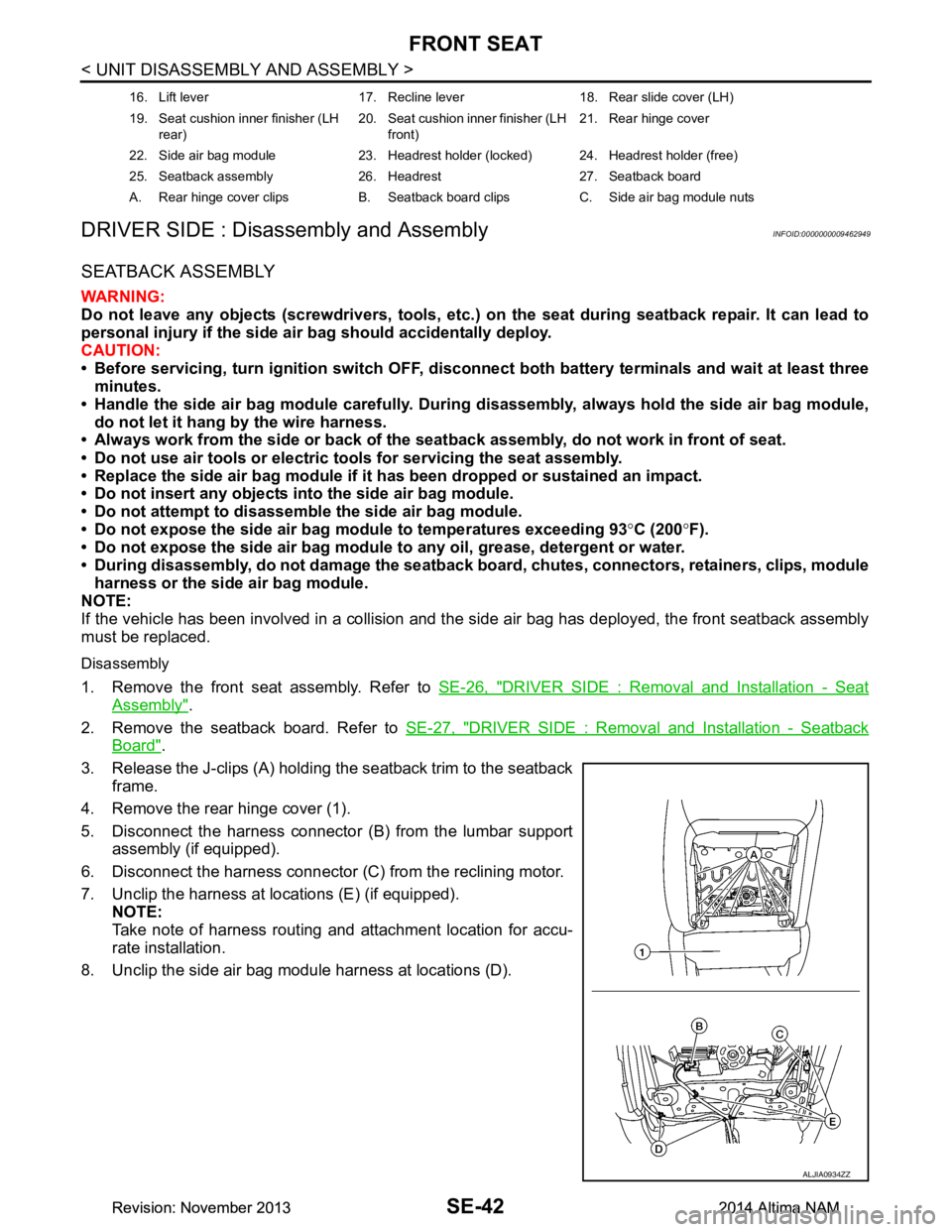
3. Release the J-clips (A) holding the seatback trim to the seatback frame.
4. Remove the rear hinge cover (1).
5. Disconnect the harness connector (B) from the lumbar support assembly (if equipped).
6. Disconnect the harness connector (C) from the reclining motor.
7. Unclip the harness at locations (E) (if equipped). NOTE:
Take note of harness routing and attachment location for accu-
rate installation.
8. Unclip the side air bag module harness at locations (D).
16. Lift lever 17. Recline lever 18. Rear slide cover (LH)
19. Seat cushion inner finisher (LH rear) 20. Seat cushion inner finisher (LH
front) 21. Rear hinge cover
22. Side air bag module 23. Headrest holder (locked) 24. Headrest holder (free)
25. Seatback assembly 26. Headrest 27. Seatback board
A. Rear hinge cover clips B. Seatback board clips C. Side air bag module nuts
ALJIA0934ZZ
Revision: November 20132014 Altima NAMRevision: November 20132014 Altima NAM
Page 3796 of 4801
FRONT SEATSE-47
< UNIT DISASSEMBLY AND ASSEMBLY >
C
D E
F
G H
I
K L
M A
B
SE
N
O P
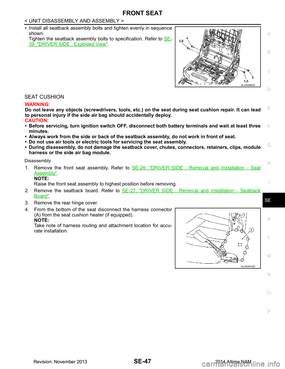
• Install all seatback assembly bolts and tighten evenly in sequence shown.
Tighten the seatback assembly bolts to specification. Refer to SE-
39, "DRIVER SIDE : Exploded View".
SEAT CUSHION
WARNING:
Do not leave any objects (screwdrivers, tools, etc. ) on the seat during seat cushion repair. It can lead
to personal injury if the side air bag should accidentally deploy.
CAUTION:
• Before servicing, turn ignition swit ch OFF, disconnect both battery terminals and wait at least three
minutes.
• Always work from the side or back of the seat back assembly, do not work in front of seat.
• Do not use air tools or electric tools for servicing the seat assembly.
• During disassembly, do not damage the seatback cover , chutes, connectors, retainers, clips, module
harness or the side air bag module.
Disassembly
1. Remove the front seat assembly. Refer to SE-26, "DRIVER SIDE : Removal and Installation - Seat
Assembly".
NOTE:
Raise the front seat assembly to highest position before removing.
2. Remove the seatback board. Refer to SE-27, "DRIVER SIDE : Removal and Installation - Seatback
Board".
3. Remove the rear hinge cover.
4. From the bottom of the seat disconnect the harness connector (A) from the seat cushion heater (if equipped).
NOTE:
Take note of harness routing and attachment location for accu-
rate installation.
ALJIA0968ZZ
ALJIA0970ZZ
Revision: November 20132014 Altima NAMRevision: November 20132014 Altima NAM