2014 MERCEDES-BENZ B-CLASS SPORTS weight
[x] Cancel search: weightPage 96 of 360
recommended for the size and weight of the
child
.For additional information, see the
"Children in the vehicle" section.
Ac hild's risk of serious or fatal injuries is
significantly increased if the child restraints
are not properly secured in the vehicle and/
or the child is not properly secured in the child
restraint.
! To avoid damage to the seats and the seat
heating, observe the following information:
R keep liquids from spilling on the seats. If
liquidiss pilled on the seats, dry them as
soon as possible.
R if the seat covers are damp or wet, do not
switch on the seat heating. The seat
heating should also not be used to dry
the seats.
R clean the seat covers as recommended;
see the "Interior care" section.
R do not transport heavy loads on the
seats. Do not place sharp objectsont he
seat cushions, e.g. knives, nails or tools.
The seats should only be occupied by
passengers, if possible.
R when the seat heating is in operation, do
not cover the seats with insulating
materials, e.g. blankets, coats, bags,
seat covers, child seats or booster seats.
! Make sure that there are no objectsint he
footwell or behind the seats when resetting
the seats. There is arisk that the seats
and/or the objectsc ould be damaged.
i The head restraintsint he front and rear
seats can be removed. 1
For more information ,contact aqualified
specialist workshop.
i Further related subjects:
R Luggage compartmente nlargement
(folding down the rea rseats)
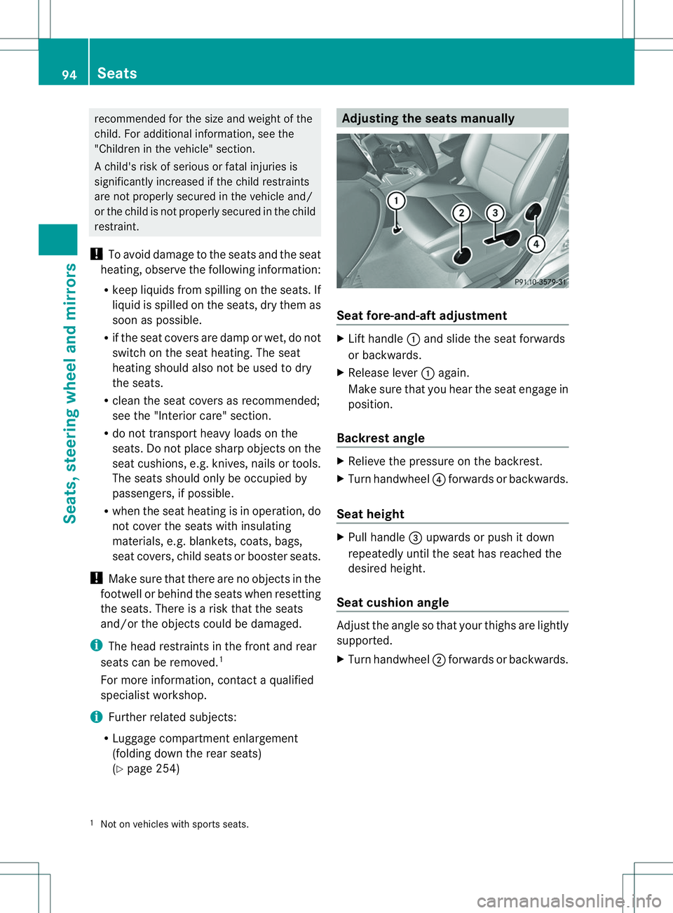
(Y page 254) Adjusting the seats manually
Seat fore-and-aft adjustment
X
Lift handle 001Aand slide the seat forwards
or backwards.
X Release lever 001Aagain.
Make sure that you hear the seat engage in
position.
Backrest angle X
Relieve the pressure on the backrest.
X Turn handwheel 0021forwards or backwards.
Seat height X
Pull handle 0023upwards or push it down
repeatedly until the seat has reached the
desired height.
Seat cushion angle Adjust the angle so that your thighs are lightly
supported.
X
Turn handwheel 0010forwards or backwards.
1 Not on vehicles with sport sseats. 94
SeatsSeats, steering wheel and mirrors
Page 220 of 360
Display messages Possible causes/consequences and
000B Solutions
Front Passenger
Airbag Disabled
See Operator's
Manual The front-passenger air bag is disabled during th
ejou rney, even
though:
R an adult
or
R ap erson larger than acertai nsizeiso ccupyin gthe front-
passenger seat
If additional forces are applied to th eseat ,the system may
interpret th eoccupant's weight as lowe rthan it actually is.
G WARNING
The front-passenger air bag does not deploy during an accident.
There is an increased risk of injury.
X Pull over and stop the vehicle safely as soon as possible, paying
attention to road and traffic conditions.
X Secure the vehicle against rolling away (Y page 152).
X Switch the ignition off.
X Have the occupant get out of the vehicle.
X Keep the seat unoccupied, close the front-passenger door and
switch on the ignition.
X Observe the PASSENGER AIR BAG OFF indicator lamp in the
center console and the multifunction displaya nd check the
following:
Seat unoccupied and ignition switched on:
R the PASSENGER AIR BAG OFF indicator lamp must light up and
remain lit. If the indicator lamp is on, OCS has disabled the front-
passenger air bag (Y page 47).
R the Front Passenger Airbag Enabled See Operator's Manual or
Front Passenger Airbag Disabled See Operator's Manual displaym
essages must not be shown in
the multifunction display.
X Wait for aperiod of at least 60 seconds until the necessary
system checksh ave been completed.
X Make sure that the displaym essages do not appearinthe
multifunction display.
If these conditionsa re fulfilled,the front-passenger seat can be
occupied again. Whether the PASSENGER AIR BAG OFF indicator
lamp remains lit or goes out depends on how OCS classifies the
occupant.
If the conditionsa re not fulfilled,the system is not operating
correctly.
X Visit aqualified specialist workshop immediately. 218
Display messagesOn-board computer and displays
Page 221 of 360
Display messages Possible causes/consequences and
000B Solutions
Fo
rfurther information about th eOccupant Classification System,
see (Y page 47). Front Passenger
Airbag Enabled See
Operator'
sManual The front-passenger air bag is enabled durin
gthe journey, even
though:
R ac hild, asmal ladult or an object weighing less than the
system' sweigh tthreshold is located on the front-passenger
seat
or
R the front-passenger seat is unoccupied
The system may detect objectsorf orces applying additional
weight on the seat.
G WARNING
The air bag may deploy unintentionally.
There is an increased risk of injury.
X Pull over and stop the vehicle safely as soon as possible, paying
attention to road and traffic conditions.
X Secure the vehicle against rolling away (Y page 152).
X Switch the ignition off.
X Open the front-passenger door.
X Remove the child and the child restraint system from the front-
passenger seat.
X Make sure that there are no objectsont he seat adding to the
weight.
The system may otherwise detect the additional weight and
interpret the seat occupant's weight as greater than it actually
is.
X Keep the seat unoccupied, close the front-passenger door and
switch on the ignition.
X Observe the PASSENGER AIR BAG OFF indicator lamp in the
center console and the multifunction displaya nd check the
following:
Seat unoccupied and ignition switched on:
R the PASSENGER AIR BAG OFF indicator lamp must light up and
remain lit. If the indicator lamp is on, OCS (Occupant
Classification System) has disabled the front-passenger air bag
(Y page 47).
R the Front Passenger Airbag Enabled See Operator's Manual or
Front Passenger Airbag Disabled See Operator's Manual displaym
essages must not be shown in
the multifunction display. Display messages
219On-board computer and displays Z
Page 252 of 360
Useful information
i This Operator's Manual describes all
models and all standard and optional
equipment of your vehicle available at the
time of publication of the Operator's
Manual. Country-specific differences are
possible. Please not ethat your vehicle may
not be equipped with all features
described. This also applies to safety-
related system sand functions.
i Read the information on qualified
specialist workshops: (Y page 25).Loading guidelines
G
WARNING
If objects, luggage or loads are not secured or
not secured sufficiently, they could slip, tip
over or be flung around and thereby hit vehicle
occupants .There is arisk of injury,
particularly in the even tofsudden braking or
as udde nchange in direction.
Always store objectssot hat they cannot be
flung around. Secure objects, luggageor
loads against slipping or tipping before the
journey. G
WARNING
Combustion engines emit poisonous exhaust
gases such as carbon monoxide. If the tailgate
is open when the engine is running,
particularly if the vehicle is moving, exhaust
fumes could enter the passenger
compartment. There is arisk of poisoning.
Turn off the engine before opening the
tailgate. Never drive with the tailgate open.
The handling characteristics of aladen
vehicle are dependent on the distribution of
the load within the vehicle. For this reason,
you should observe the following notes when
transporting aload:
R Never exceed the maximum permissible
gross vehicle weight or the gross axle weight rating of the vehicle (including
occupants). The values are specified on the
vehicle identification plate on the B-pillar of
the driver's door.
R The cargo compartmentist he preferred
place to carry objects.
R Position heavy loads as far forwards as
possible and as low down in the cargo
compartmentasp ossible.
R The load must not protrude above the
upper edge of the seat backrests.
R Alwaysp lace the load against the rear or
front seat backrests. Make sure that the
seat backrests are securely locked into
place.
R Alwaysp lace the load behind unoccupied
seats if possible.
R Use the cargo tie down rings and the parcel
nets to transport loads and luggage.
R Use cargo tie-down rings and fastening
materials appropriate for the weight and
size of the load.
R Hook in the cargo net when loading.
R The maximum load capacity of the stowage
well under the cargo compartment floor is
55 lbs (25 kg).
R Secure the load with sufficiently strong and
wear-resistant tie-downs. pad sharp edges
for protection.
! Do not position the load on one part of the
folding cargo compartment floor only. The
maximum load capacity of the folding cargo
compartment floor is 220 lbs (100 kg).
Distribute the weight evenly to avoid
damaging the cargo compartment floor.
Place asolid board under the load if
necessary. Please note that the load on the
cargo compartment floor will be increased
when the load is lashed down. 250
Loading guidelinesStowage and features
Page 264 of 360
R
Close th elockable stowage spaces while
driving.
R Stow and secure object sthata re heavy,
hard ,pointy, sharp-edged ,fra gile or too
large in th ecargo compartment.
! Only use th ecup holders for containers of
th er igh tsize and which have lids. The
drinks could otherwise spill.
The stowage compartments in the doors
provide space for bottles:
R front :capacity up to 51 fl. oz. (1. 5l)
R rear: capacity up to 17 fl. oz. (0. 5l)
Cup holder in th efront-compartment
center console The cup holder and the rubber mat
underneat
hcan be removed for cleaning.
Clean the mwith clean ,lukewarm water only. X
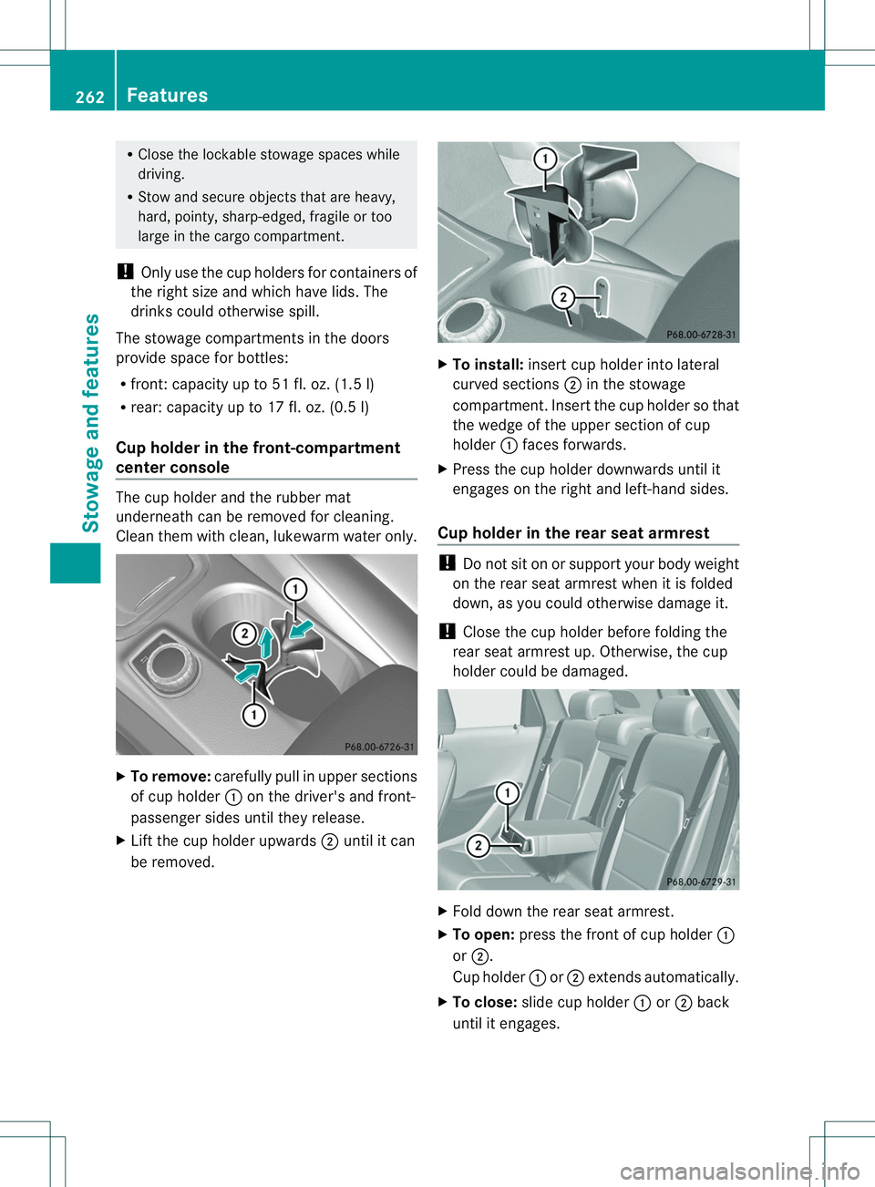
To remove: carefully pull in upper sections
of cup holder 001Aon the driver's and front-
passenger sides until the yrelease.
X Lift the cup holder upwards 0010until it can
be removed. X
To install: insert cup holder int olateral
curved sections 0010in the stowage
compartment. Insert the cup holder so that
the wedge of the upper section of cup
holder 001Aface sforwards.
X Press the cup holder downwards until it
engages on the right and left-han dsides.
Cup holder in th erears eat armrest !
Do not sit on or support your body weight
on the rear seat armrest when it is folded
down, as you could otherwise damage it.
! Close the cup holder befor efoldin gthe
rear seat armrest up. Otherwise ,the cup
holder could be damaged. X
Fold down the rear seat armrest.
X To open: press the front of cup holder 001A
or 0010.
Cup holder 001Aor0010 extends automatically.
X To close: slide cup holder 001Aor0010 back
until it engages. 262
FeaturesStowage and features
Page 307 of 360
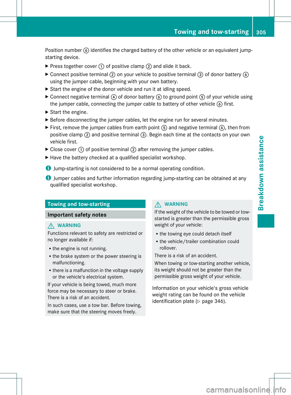
Position number
0024identifies the charged batter yofthe other vehicle or an equivalent jump-
starting device.
X Press together cover 001Aof positive clamp 0010and slide it back.
X Connec tpositive terminal 0010on your vehicle to positive terminal 0023of donor battery 0024
using the jumper cable, beginning with your own battery.
X Start the engine of the donor vehicle and run it at idling speed.
X Connect negative terminal 0021of donor battery 0024to ground point 001Eof your vehicle using
the jumper cable, connectingt he jumper cable to battery of other vehicle 0024first.
X Start the engine.
X Before disconnectingt he jumper cables, let the engine run for several minutes.
X First,r emove the jumper cables from earth point 001Eand negative terminal 0021,then from
positive clamp 0010and positive terminal 0023.Begin each time at the contacts on your own
vehicle first.
X Close cover 001Aof positive terminal 0010after removing the jumper cables.
X Have the battery checked at aqualified specialist workshop.
i Jump-starting is not considered to be anormal operating condition.
i Jumper cables and further information regarding jump-starting can be obtained at any
qualified specialist workshop. Towing and tow-starting
Important safety notes
G
WARNING
Functions relevant to safety are restricted or
no longer available if:
R the engine is not running.
R the brake system or the power steerin gis
malfunctioning.
R there is amalfunction in the voltage supply
or the vehicle's electrical system.
If your vehicle is being towed, much more
force may be necessary to steer or brake.
There is arisk of an accident.
In such cases, use atow bar. Before towing,
make sure that the steering moves freely. G
WARNING
If the weight of the vehicle to be towed or tow-
started is greater than the permissible gross
weight of your vehicle:
R the towing eye could detach itself
R the vehicle/trailer combination could
rollover.
There is arisk of an accident.
When towing or tow-starting another vehicle,
its weight should not be greater than the
permissible gross weight of your vehicle.
Information on your vehicle's gross vehicle
weight rating can be found on the vehicle
identification plate (Y page 346). Towing and tow-starting
305Breakdown assistance Z
Page 325 of 360
X
Set the tire pressure to the value
recommended for the corresponding
driving situation on the Tire and Loading
Information placard on the driver' sside
B-pillar (Y page 315).
Additiona ltire pressure value sfor different
load scan also be found on the tire pressure
table on the inside of the fue lfille rflap
(Y page 315).
X Make sure that the tir epressure is correct
on all four wheels.
X Make sure that the SmartKey is in position
2in the ignition lock.
X Press 000Aor0004 on the steerin gwheel
to selec tthe Service menu.
X Press the 0006or0005 button to select
Tire Pressure .
X Press the 000Cbutton.
The multifunction displays hows the
current tire pressure for the individualt ires
or the Tire pressures will be displayed after driving
afew minutes message.
X Press the 0005button.
The Use Current Pressures as New Reference Values message appears in
the multifunction display.
If you wish to confirm the restart:
X Press the 000Cbutton.
The Tire Pressure Monitor Restarted message appears in the
multifunction display.
After driving for afew minutes, the system
checksw hether the current tire pressures
are within the specified range. The new tire
pressures are then accepted as reference
values and monitored.
If you wish to cancel the restart:
X Press the 0002button.
The tire pressure values stored at the last
restart will continue to be monitored. Loading the vehicle
Instruction labels for tires and loads
G
WARNING
Overloaded tires can overheat, causing a
blowout. Overloaded tires can also impair the
steering and driving characteristics and lead
to brake failure. There is arisk of accident.
Observe the load rating of the tires. The load
rating must be at least half of the GAWR of
your vehicle. Never overload the tires by
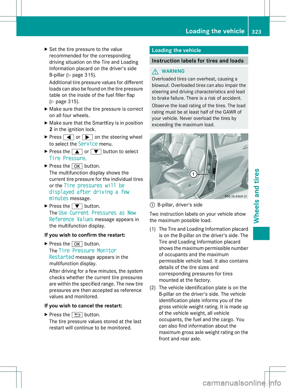
exceeding the maximum load. 001A
B-pillar, driver's side
Two instruction labelsony our vehicle show
the maximum possible load.
(1) The Tire and Loading Information placard is on the B-pillar on the driver's side. The
Tire and Loading Information placard
shows the maximum permissible number
of occupants and the maximum
permissible vehicle load. It also contains
details of the tire sizes and
corresponding pressures for tires
mounted at the factory.
(2) The vehicle identification plate is on the B-pillar on the driver's side. The vehicle
identification plate informs you of the
gross vehicle weight rating. It is made up
of the vehicle weight, all vehicle
occupants, the fuel and the cargo. You
can also find information about the
maximum gross axle weight rating on the
front and rear axle. Loading the vehicle
323Wheels and tires Z
Page 326 of 360
The maximum gross axle weight rating is
the maximum weight that can be carried
by one axle (front or rear axle). Never
exceed the maximum load or the
maximum gross axle weight rating for the
frontorr ear axle. Maximum permissible gross vehicle
weight rating
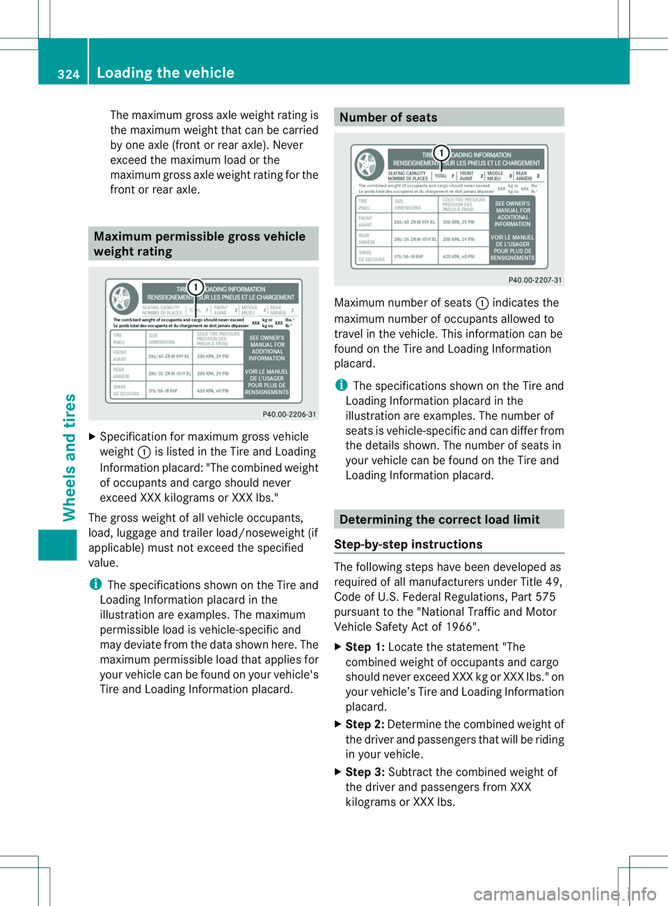
X
Specification for maximum gross vehicle
weight 001Ais listed in the Tire and Loading
Information placard: "The combined weight
of occupant sand cargo should never
exceed XXX kilograms or XXX lbs."
The gross weight of all vehicle occupants,
load, luggage and trailer load/noseweight (if
applicable) must not exceed the specified
value.
i The specification sshown on the Tire and
Loading Information placard in the
illustration are examples. The maximum
permissible load is vehicle-specific and
may deviate from the data shown here. The
maximum permissible load that applies for
your vehicle can be found on your vehicle's
Tire and Loading Information placard. Number of seats
Maximum number of seats
001Aindicates the
maximum number of occupant sallowed to
travel in the vehicle. This information can be
found on the Tire and Loading Information
placard.
i The specification sshown on the Tire and
Loading Information placard in the
illustration are examples. The number of
seats is vehicle-specific and can differ from
the details shown. The number of seats in
your vehicle can be found on the Tire and
Loading Information placard. Determining the correct load limit
Step-by-step instructions The following steps have been developed as
required of all manufacturers under Title 49,
Code of U.S.F
ederal Regulations, Part 575
pursuant to the "National Traffic and Motor
Vehicle Safet yActof 1966".
X Step 1: Locatethe statement "The
combined weight of occupants and cargo
should never exceed XXX kg or XXX lbs." on
your vehicle’s Tire and Loading Information
placard.
X Step 2: Determine the combined weight of
the driver and passengers that will be riding
in your vehicle.
X Step 3: Subtract the combined weight of
the driver and passengers from XXX
kilograms or XXX lbs. 324
Loading thev
ehicleWheels and tires