2014 MERCEDES-BENZ B-CLASS SPORTS trailer
[x] Cancel search: trailerPage 174 of 360
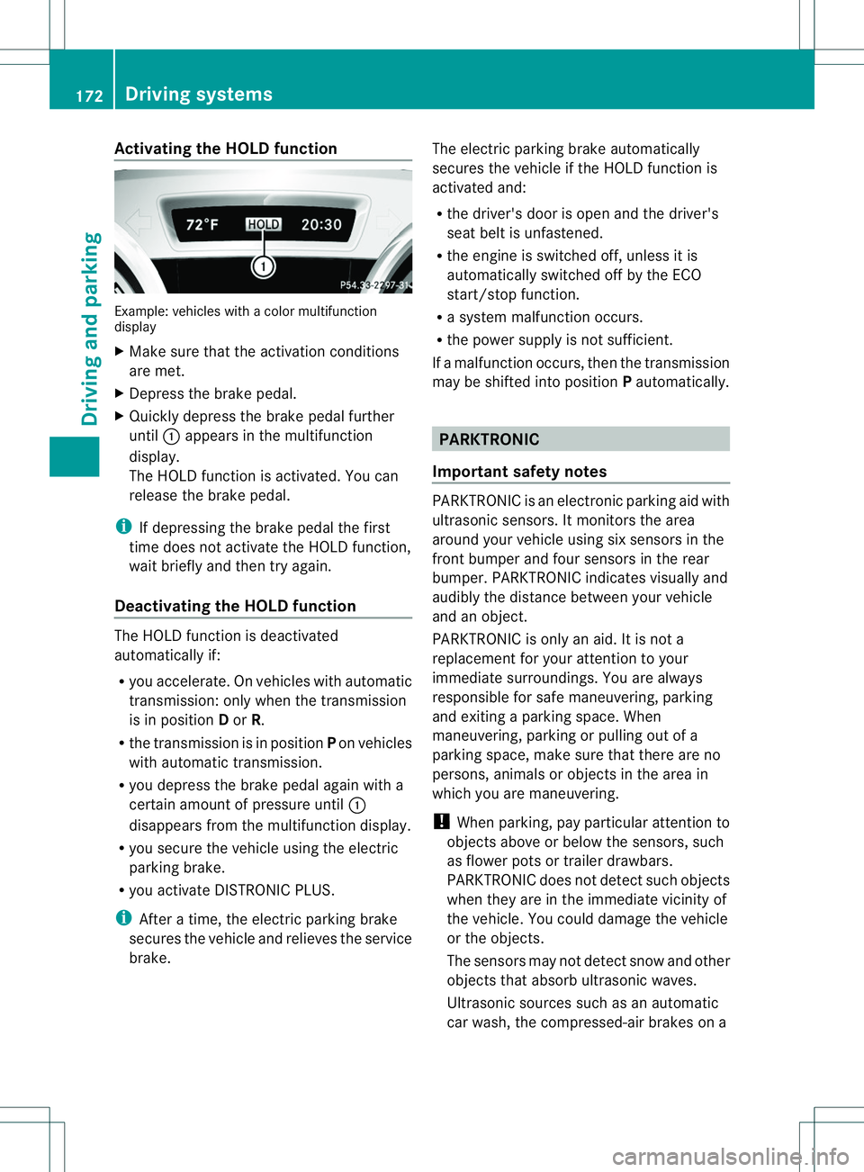
Activating th
eHOLD function Example: vehicles wit
hacolor multifunction
display
X Mak esuret hatthe activation conditions
are met.
X Depress th ebrak epedal.
X Quickl ydepress th ebrak epedal further
until 001Aappear sinthemultifunction
display.
The HOLD function is activated. You can
release th ebrak epedal.
i If depressing th ebrak epedal th efirst
time does no tactivat ethe HOLD function,
wait briefly and then tr yagain.
Deactivating th eHOLD function The HOLD function is deactivated
automatically if:
R
you accelerate .Onvehicles with automatic
transmission :only when the transmission
is in position Dor R.
R the transmission is in position Pon vehicles
with automatic transmission.
R yo ud epress the brake peda lagain with a
ce rtain amoun tofpressure until 001A
disappears from the multifunction display.
R you secure the vehicl eusing the electric
parking brake.
R you activate DISTRONIC PLUS.
i After atime, the electric parking brake
secure sthe vehicl eand relieves the service
brake. The electric parking brake automatically
secure
sthe vehicl eifthe HOLD function is
activated and:
R the driver's door is open and the driver's
seat beltisu nfastened.
R the engine is switched off, unless it is
automaticallys witched off by the ECO
start/stop function.
R as ystem malfunction occurs.
R the power supplyisn ot sufficient.
If am alfunction occurs, then the transmission
may be shifted into position Pautomatically. PARKTRONIC
Important safety notes PARKTRONIC is an electronic parking aid with
ultrasonic sensors. It monitors the area
around your vehicle using six sensors in the
front bumper and four sensors in the rear
bumper. PARKTRONIC indicates visually and
audibly the distance between your vehicle
and an object.
PARKTRONIC is only an aid. It is not a
replacement for your attention to your
immediate surroundings. You are always
responsible for safe maneuvering, parking
and exiting
aparking space. When
maneuvering, parking or pulling out of a
parking space, make sure that there are no
persons, animals or objects in the area in
which you are maneuvering.
! When parking, pay particular attention to
objects above or below the sensors, such
as flower pots or trailer drawbars.
PARKTRONIC does not detect such objects
when they are in the immediate vicinity of
the vehicle. You could damage the vehicle
or the objects.
The sensors may not detect snow and other
objects that absorb ultrasonic waves.
Ultrasonic sources such as an automatic
car wash, the compressed-air brakes on a 172
Driving systemsDriving and parking
Page 178 of 360
Activ
eParking Assist ma ypossibl yindicate
parking space swhich ar enot suitabl efor
parking ,for example:
R where parking or stopping is prohibited
R in front of driveway sorentrances and exits
R on unsuitable surfaces
Parking tips:
R On narrow roads ,drive as close to the
parking space as possible.
R Parking space sthata re littered or
overgrow nmight be identified or measured
incorrectly.
R Parking spaces that are partially occupied
by trailer drawbars might not be identified
as such or be measure dincorrectly.
R Snowfall or heavy rain may lead to aparking
space being measure dinaccurately.
R Pay attention to the PARKTRONIC
(Y page 173 )warning messages durin gthe
parking procedure.
R You can interven einthesteering procedure
to correct it at any time. Activ eParking
Assist will then be canceled.
R When transportin gaload whic hprotrudes
from your vehicle ,you should no tuse
Active Parking Assist.
R Never use Active Parking Assist when snow
chains are installed.
R Make sure that the tire pressures are
always correct.T his hasadirec tinfluence
on the parking characteristics of the
vehicle.
Use Active Parking Assist for parking spaces:
R tha tare paralleltot he direction of travel
R that are on straight roads, not bends
R that are on the same leve lasthe road ,e.g.
not on the pavement
Detectin gparking spaces Objects located above the height range of
Active Parking Assist willn ot be detected
when the parking space is measured. These
are not taken into account when the parking procedure is calculated
,e.g. overhanging
loads, tail sections or loading ramps of goods
vehicles. G
WARNING
If there are objects above the detection range,
Active Parking Assist may turn prematurely.
You may caus eacollision as aresult. There is
ar isk of an accident.
If there are objects above the detection range,
stop and deactivate Active Parking Assist.
For further information on the detection
range (Y page173).
Active Parking Assist does not support you
with parking spaces paralleltot he direction
of travel if:
R the parking space is on acurb
R thep arking spac eisapparentl yblocked,
for example by foliage or gras spaving
blocks
R ther ange of movement is to osmall
R thep arking spac eisbordered by an
obstacle whic hisnot clearly defined such
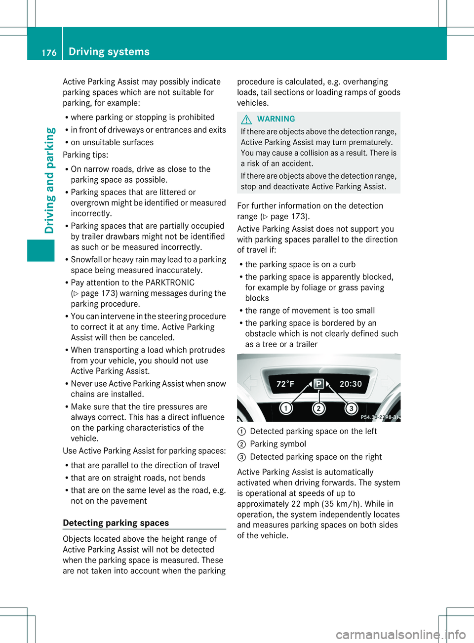
as atreeorat railer 001A
Detected parking space on the left
0010 Parking symbol
0023 Detected parking space on the right
Activ eParking Assist is automatically
activated when drivin gforwards. The system
is operational at speeds of up to
approximately 22 mph (35 km/h). While in
operation, the system independently locates
and measure sparking spaces on bot hsides
of the vehicle. 176
Driving systemsDriving and parking
Page 182 of 360
Important safety notes
The rear view camera is only an aid. It is not
ar eplacemen tfor your attention to your
immediat esurroundings. You are always
responsible for saf emaneuverin gand
parking .When maneuvering or parking, make
sure that there are no persons, animals or
objectsint he area in which you are
maneuvering.
Under the following circumstances, the rear
view camera will not function, or will function
in alimited manner:
R the tailgate is open
R in heavy rain, snow or fog
R at night or in very dark places
R if the camera is exposed to very bright light
R if the area is lit by fluorescent light or LED
lighting (the displaym ay flicker)
R if there is asudden change in temperature,
e.g. when driving into aheated garage in
winter
R if the camera lens is dirty or obstructed
R if the rear of your vehicle is damaged. In
this event, have the camera position and
settingc hecked at aqualified specialist
workshop
The field of vision and other functions of the
rear view camera may be restricted due to
additional accessories on the rear of the
vehicle (e.g. license plate holder, bicycle
rack).
Activating/deactivating the rear view
camera X
To activate: make sure that the SmartKey
is in position 2in the ignition lock.
X Make sure that in the audios ystem/
COMAND ,the "Activation by Rgear"
function is selected; see th eseparate operatin
ginstructions fort he audio
system/COMAND.
X Engage reverse gear.
Guidel ines are used to show the area
behind the vehicle in the Audio/COMAND
display.
To deactivate: the rear view camera
deactivates if you shift the transmission to P
on vehicles with automatic transmission or
after driving forwards ashort distance.
Displays in the Audio/COMAND display The rear view camera may show
adistorted
view of obstacles, show them incorrectly or
not at all. The rear view camera does not show
objectsint he following positions:
R very close to the rear bumper
R under the rear bumper
R in the area immediately above the tailgate
handle
! Objectsn ot at ground level may appearto
be further away than they actually are, e.g.:
R the bumper of aparked vehicle
R the drawbar of atrailer
R the ball coupling of atrailer tow hitch
R the rear section of an HGV
R as lanted post
Use the guidelines only for orientation.
Approac hobjects no further than the
bottom-most guideline. 180
Driving systemsDriving and parking
Page 244 of 360
Problem Possible causes/consequences and
000B Solutions
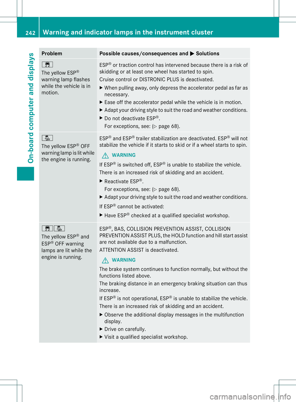
000A
The yellowE
SP®
warning lamp flashes
while the vehicle is in
motion. ESP
®
or traction control has intervened because there is arisk of
skidding or at least one wheel has started to spin.
Cruise control or DISTRONIC PLUS is deactivated.
X When pulling away,o nly depress the accelerator pedal as far as
necessary.
X Ease off the accelerator pedal while the vehicle is in motion.
X Adapt your driving style to suit the road and weather conditions.
X Do not deactivate ESP ®
.
For exceptions, see: (Y page 68).0004
The yellowE
SP®
OFF
warning lamp is lit while
the engine is running. ESP
®
and ESP ®
trailer stabilization are deactivated. ESP ®
will not
stabilize the vehicle if it starts to skid or if awheel starts to spin.
G WARNING
If ESP ®
is switched off, ESP ®
is unable to stabilize the vehicle.
There is an increased risk of skidding and an accident.
X Reactivate ESP ®
.
For exceptions, see: (Y page 68).
X Adapt your driving style to suit the road and weather conditions.
If ESP ®
cannot be activated:
X Have ESP ®
checked at aqualified specialist workshop. 000A0004
The yellow ESP
®
and
ESP ®
OFF warning
lamps are lit while the
engine is running. ESP
®
,B AS,C OLLISION PREVENTION ASSIST, COLLISION
PREVENTION ASSIST PLUS, the HOLD function and hill start assist
are not available due to amalfunction.
ATTENTION ASSIST is deactivated.
G WARNING
The brake system continues to function normally, but without the
functions listed above.
The braking distance in an emergency braking situation can thus
increase.
If ESP ®
is not operational, ESP ®
is unable to stabilize the vehicle.
There is an increased risk of skidding and an accident.
X Observe the additional display messages in the multifunction
display.
X Drive on carefully.
X Visit aqualified specialist workshop. 242
Warning and indicator lampsint
he instrument clusterOn-board computer and displays
Page 307 of 360
Position number
0024identifies the charged batter yofthe other vehicle or an equivalent jump-
starting device.
X Press together cover 001Aof positive clamp 0010and slide it back.
X Connec tpositive terminal 0010on your vehicle to positive terminal 0023of donor battery 0024
using the jumper cable, beginning with your own battery.
X Start the engine of the donor vehicle and run it at idling speed.
X Connect negative terminal 0021of donor battery 0024to ground point 001Eof your vehicle using
the jumper cable, connectingt he jumper cable to battery of other vehicle 0024first.
X Start the engine.
X Before disconnectingt he jumper cables, let the engine run for several minutes.
X First,r emove the jumper cables from earth point 001Eand negative terminal 0021,then from
positive clamp 0010and positive terminal 0023.Begin each time at the contacts on your own
vehicle first.
X Close cover 001Aof positive terminal 0010after removing the jumper cables.
X Have the battery checked at aqualified specialist workshop.
i Jump-starting is not considered to be anormal operating condition.
i Jumper cables and further information regarding jump-starting can be obtained at any
qualified specialist workshop. Towing and tow-starting
Important safety notes
G
WARNING
Functions relevant to safety are restricted or
no longer available if:
R the engine is not running.
R the brake system or the power steerin gis
malfunctioning.
R there is amalfunction in the voltage supply
or the vehicle's electrical system.
If your vehicle is being towed, much more
force may be necessary to steer or brake.
There is arisk of an accident.
In such cases, use atow bar. Before towing,
make sure that the steering moves freely. G
WARNING
If the weight of the vehicle to be towed or tow-
started is greater than the permissible gross
weight of your vehicle:
R the towing eye could detach itself
R the vehicle/trailer combination could
rollover.
There is arisk of an accident.
When towing or tow-starting another vehicle,
its weight should not be greater than the
permissible gross weight of your vehicle.
Information on your vehicle's gross vehicle
weight rating can be found on the vehicle
identification plate (Y page 346). Towing and tow-starting
305Breakdown assistance Z
Page 309 of 360
X
Place the towing eye in the stowage well
beneath the cargo compartment floor
(Y page 294) in the cargo compartment.
X Vehicles with the TIREFI Tkit: put back the
tire inflation compressor. Towing the vehicle with the front axle
raised
! The ignition must be switched off if the
vehicle is being towed with the fronta xle
raised .Otherwise, ESP ®
ma yintervene and
damage the brake system.
X Turn the SmartKe ytoposition 2in the
ignition lock.
X When the vehicl eisstationary, depress the
brake peda land kee pitdepressed.
X Shift the automatic transmission to
position P.
X Releas ethe brake pedal.
X Releas ethe electric parking brake.
X Switch off the automatic locking
(Y page 205).
X Switch on the hazar dwarning lamps
(Y page 107).
X Turn the SmartKe ytoposition 0in the
ignition lock and leav ethe SmartKe yinthe
ignition lock.
Observe the important safety note swhen
towing your vehicl ewitht he front axl eraised
( Y page 305). Towin
gavehicle with both axles on
th eg round
i In orde rtosignal achange of direction
when towing with the hazard warning lamps
switched on, use the combination switch as
usual.Int his case, only the indicator lamps
for the direction of travel flash. After
resettingt he combination switch, the
hazard warning lamp starts flashing again. The automatic transmission automatically
shifts to position
Pwhen you open the driver's
or front-passenger door or when you remove
the SmartKey from the ignition lock. In order
to ensure that the automatic transmission
stays in position Nwhen towing the vehicle,
you must observe the following points:
X Make sure that the vehicle is stationary.
X Turn the SmartKey to position 2in the
ignition lock.
X Depress and hold the brake pedal.
X Shift the automatic transmission to
position N.
X Leave the SmartKey in position 2in the
ignition lock.
X Release the brake pedal.
X Release the electric parking brake.
X Switch on the hazard warning lamps
(Y page 107).
It is important that you observe the safety
instructions when towing away your vehicle
(Y page 305). Transporting the vehicle
! You may only secure the vehicle by the
wheels, not by parts of the vehicle such as
axle or steering components. Otherwise,
the vehicle could be damaged.
X Turn the SmartKey to position 2in the
ignition lock.
X Shift the transmission to position N.
As soon as the vehicle has been loaded:
X Prevent the vehicle from rolling away by
applying the electric parking brake.
X Shift the transmission to position P.
X Turn the SmartKey to position 0in the
ignition lock and remove it.
X Secure the vehicle.
The towing eye can be used to pull the vehicle
onto atrailer or transporter for transporting
purposes. Towing and tow-starting
307Breakdown assistance Z
Page 326 of 360
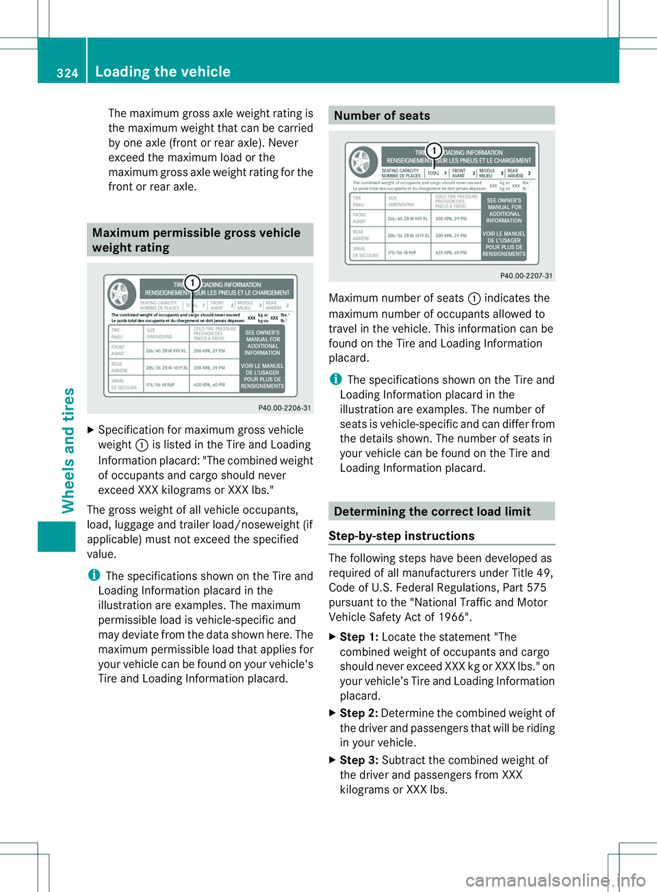
The maximum gross axle weight rating is
the maximum weight that can be carried
by one axle (front or rear axle). Never
exceed the maximum load or the
maximum gross axle weight rating for the
frontorr ear axle. Maximum permissible gross vehicle
weight rating
X
Specification for maximum gross vehicle
weight 001Ais listed in the Tire and Loading
Information placard: "The combined weight
of occupant sand cargo should never
exceed XXX kilograms or XXX lbs."
The gross weight of all vehicle occupants,
load, luggage and trailer load/noseweight (if
applicable) must not exceed the specified
value.
i The specification sshown on the Tire and
Loading Information placard in the
illustration are examples. The maximum
permissible load is vehicle-specific and
may deviate from the data shown here. The
maximum permissible load that applies for
your vehicle can be found on your vehicle's
Tire and Loading Information placard. Number of seats
Maximum number of seats
001Aindicates the
maximum number of occupant sallowed to
travel in the vehicle. This information can be
found on the Tire and Loading Information
placard.
i The specification sshown on the Tire and
Loading Information placard in the
illustration are examples. The number of
seats is vehicle-specific and can differ from
the details shown. The number of seats in
your vehicle can be found on the Tire and
Loading Information placard. Determining the correct load limit
Step-by-step instructions The following steps have been developed as
required of all manufacturers under Title 49,
Code of U.S.F
ederal Regulations, Part 575
pursuant to the "National Traffic and Motor
Vehicle Safet yActof 1966".
X Step 1: Locatethe statement "The
combined weight of occupants and cargo
should never exceed XXX kg or XXX lbs." on
your vehicle’s Tire and Loading Information
placard.
X Step 2: Determine the combined weight of
the driver and passengers that will be riding
in your vehicle.
X Step 3: Subtract the combined weight of
the driver and passengers from XXX
kilograms or XXX lbs. 324
Loading thev
ehicleWheels and tires
Page 327 of 360
X
Step 4: The resulting figure equalst he
available amount of cargo and luggagel oad
capacity. For example, if the "XXX" amount
equals1 400 lbs and there are five
occupants in the vehicle each with aweight
of 150 lbs, the amount of available cargo
and luggagel oad capacity is 650 lbs (1400
000F 750 (5 x150) =650 lbs).
X Step 5: Determine the combined weight of
luggagea nd cargo being loaded on the
vehicle. That weight may not safely exceed
the available cargo and luggagel oad
capacity calculated in step 4.
X Step 6(if applicable): If your vehicle will
be towing atrailer, load from your trailer
will be transferred to your vehicle. Refer to
this Operator's Manual to determine how
this reduces the available cargo and
luggagel oad capacity of your vehicle
(Y page 327). Loading the vehicle
325Wheels and tires Z