Page 169 of 287
 Owners Manual Warning lights in the instrument clusterIlluminatesDescriptionThe system is active, but not ready to intervene.The system is active and ready to intervene or is currently
intervening.
Inform")
Warning lights in the instrument clusterIlluminatesDescriptionThe system is active, but not ready to intervene.The system is active and ready to intervene or is currently
intervening.
Information messages
First read and observe the introductory information and safety warn-
ings
on page 164.
The messages and information are indicated in the instrument cluster display.
Lane Assist not available. No sensor view.
The windscreen is dirty, iced over or misted up in the camera viewing range. Clean the windscreen or remove the obstacles.
Lane Assist currently not available.
The system has limited functionality due to a temporary error. Try to re-activate the machine.
Error: Lane Assist
A system error is present. Seek help from a specialist garage. Lane Assist: take over steering!
The system has detected that there are no hands on the steering wheel. In this
case, the Assist system is not ready to intervene. Place your hands on the steer-
ing wheel.
Traffic sign recognition
Introduction
This chapter contains information on the following subjects:
Function
166
Notifications and settings
167
Information messages
167WARNING■ Traffic sign detection only operates as a support. Real traffic signs always
have priority over electronic displays. The driver is always responsible for cor-
rectly assessing the traffic situation.■
Traffic signs may not be recognised at all by the system, or may be recog-
nised incorrectly. As a result, the traffic signs may not be displayed at all, or
the wrong one may appear.
■
Traffic sign recognition does not warn about exceeding the maximum per-
mitted speed nor does it adjust the driving speed to the maximum speed!
■
The display refers to the standard national speed units. For example, the
display is able top refer to km / h or mph.depending on the country.
Note
Traffic sign recognition is not available in all countries.
Function
Fig. 150
Windscreen: Camera viewing
range for traffic sign recognition
First read and observe the introductory information and safety warn- ings on page 166.
Traffic sign recognition (From here on referred to only as system) allows the fol-
lowing traffic signs recognised by the system to be shown in the instrument clus-
ter display.
› Speed limit
› Overtaking prohibited.
Additional signs, such as 'when wet' or signs which only apply for a limited time
can also be displayed.
166Driving
Page 170 of 287
 Owners Manual The system works on the basis of the data captured by the camera and is only
able to show traffic signs which are in the cameras “viewing range” » Fig. 150.
Data from the camera can be suppleme")
The system works on the basis of the data captured by the camera and is only
able to show traffic signs which are in the camera's “viewing range” » Fig. 150.
Data from the camera can be supplemented by information from the Infotainment
Navigation. This is the reason why traffic signs with maximum speeds can also be shown on sections of roads which do not have any traffic signs.
The system may not be available or may only be available to a limited extent in the following situations.
› Poor visibility conditions, e.g. fog, heavy rain, thick snowfall.
› The camera is blinded by the sun.
› The camera is blinded by the oncoming traffic.
› The camera “viewing range” is obstructed by an obstacle.
› Travelling at high speed.
› The traffic signs are fully or partially obscured (e.g. by trees, snow, dirt or other
vehicles).
› The traffic signs are not standard (round with a red border).
› The traffic signs are damaged or bent.
› The traffic signs are attached to flashing neon signs.
› The traffic signs were changed (the navigation data are out of date).
Notifications and settings
Fig. 151
Instrument cluster display: Example of the traffic sign recognition
notifications / additional notification (monochromatic display) / additional
notification (colour display)
First read and observe the introductory information and safety warn-ings
on page 166.
The detected traffic signs are indicated in the display of the instrument clus- ter » page 29 , Driving data (Multifunction display) .
■
Driving data
■ Traffic sign
Additional display
If the menu item Traffic sign is currently not shown » Fig. 151 - , the road sign
with the speed limit will appear in the upper display area of the instrument clus-
ter » Fig. 151 - , .
If several traffic signs are detected simultaneously, the next traffic sign will also
in some cases be displayed in the colour display - . All detected traffic signs can
be displayed in the menu item Traffic sign - .
The additional display traffic sign detection can be activated/deactivated in the
Infotainment » operating instructions for Infotainment , chapter Vehicle settings
(CAR button) .
Traffic sign display when towing a trailer
When towing a trailer, displaying the traffic signs which apply when towing a
trailer can be activated.
The traffic sign detection display when towing a trailer can be activated/deactiva-
ted in the Infotainment » operating instructions for Infotainment , chapter Vehicle
settings (CAR button) .
Information messages
First read and observe the introductory information and safety warn-
ings
on page 166.
The messages and information are indicated in the instrument cluster display.
No restriction at present.
No maximum speeds were recognised (e.g. on German motorways where there is
no speed limit).
Error: traffic sign recognition
A system error is present. Seek help from a specialist garage. Traffic sign recognition: clean windscreen!
The windscreen is dirty, iced over or misted up in the camera viewing range. Clean the windscreen or remove the obstacles.
Traffic sign recognition: restricted.
167Assist systems
Page 171 of 287
 Owners Manual Infotainment Navigation is not currently providing any data. Check whether the
maps are up-to-date or the whether the vehicle is currently in a location for which
no navigation data are available.")
Infotainment Navigation is not currently providing any data. Check whether the
maps are up-to-date or the whether the vehicle is currently in a location for which
no navigation data are available.
Fatigue detection (break recommendation)
Introduction
This chapter contains information on the following subjects:
Function
168
Information messages
168WARNING■ For the driving ability is always the driver's responsibility. Never drive if you
feel tired.■
The system may not detect all cases where a break is needed.
■
Therefore, take regular, sufficient breaks during long trips.
■
There will be no system warning during the so-called micro-sleep.
Note
■ In some situations, the system may evaluate the driving incorrectly and thus
mistakenly recommend a break (e.g. sporty driving, in adverse weather conditions,
or in bad road conditions).■
The fatigue detection system is designed primarily for motorway driving.
Function
First read and observe the introductory information and safety warn-ings
on page 168.
The fatigue detection system advises the driver on the basis of information about
the steering behaviour, to take a break from driving. The system recommends a
break at speeds of 65-200 km/h.
After the ignition has been switched on, the system evaluates the steering be-
haviour for 15 minutes. This baseline analysis is constantly compared with the
current steering behaviour.
If the system detects deviations from normal steering behaviour due to possible
fatigue of the driver, it recommends to take a break from driving.
The system deletes the stored baseline analysis if one of the following condi-tions is met.
› The vehicle is stopped and the ignition is turned off.
› The vehicle is stopped, the seat belt is taken off and the driver's door is opened.
› The vehicle is stopped for more than 15 minutes.
If none of these conditions is met or the driving style is not changed, the system
recommends a driving break again after 15 minutes.
The system can be activated/deactivated in the Infotainment » operating instruc-
tions for Infotainment , chapter Vehicle settings (CAR button) .
Information messages
First read and observe the introductory information and safety warn-
ings
on page 168.
The icon appears and the following message for a few seconds in the display of the instrument cluster .
Driver alert. Take a break!
DRIVER ALERT TAKE A BREAK
An audible signal is also emitted.
168Driving
Page 172 of 287
 Owners Manual Towing a trailer
Towing device
Introduction
This chapter contains information on the following subjects:
Description
169
Setting the ready position
170
Installing the ball rod
170
Check proper fitt")
Towing a trailer
Towing device
Introduction
This chapter contains information on the following subjects:
Description
169
Setting the ready position
170
Installing the ball rod
170
Check proper fitting
171
Removing the ball rod
171
Use and care
172
If your vehicle has already been factory-fitted with a towing device or is fitted
with a towing device from ŠKODA Original Accessories, then it meets all of the
technical requirements and national legal provisions for towing a trailer.
Your vehicle is fitted with a 13-pin power socket for the electrical connection be-tween the vehicle and trailer. If the trailer that is to be towed has a 7-pin connec-
tor , you can use a suitable adapter from ŠKODA Original Accessories.
Maximum Trailer drawbar load weight is 75 kg, or 80 kg for the Octavia Estate
4x4 vehicles.
WARNING■ Before each time you make a journey when using the ball rod, check that it
is seated correctly and is secured in the mounting recess.■
Do not operate the ball rod if it is not correctly inserted in the mounting re-
cess.
■
Do not operate the towing device if it is damaged or incomplete.
■
Do not perform any modifications or changes to the towing device.
■
Never release the ball rod while the trailer is still coupled.
CAUTION
Handle the ball rod carefully to avoid damaging the paintwork on the bumper.
DescriptionFig. 152
Carrier of the towing device/ball rod
First read and observe the introductory information and safety warn-
ings
on page 169.
The ball rod can be removed and can be found in the spare wheel well or in a
compartment for the spare wheel in the boot » page 236.
Explanation of graphic 13-pin power socket
Safety eye
Mounting recess
Cap
Dust cap
Ball rod
Operating lever
Lock cap
Trigger pin
Keys
Locking ball
Note
If you lose the key, please get in touch with a specialist garage.
1234567891011169Towing a trailer
Page 173 of 287
 Owners Manual Setting the ready positionFig. 153
Setting the ready position/ready position
First read and observe the introductory information and safety warn-
ings
on page 169.
Before installing always adjust t")
Setting the ready positionFig. 153
Setting the ready position/ready position
First read and observe the introductory information and safety warn-
ings
on page 169.
Before installing always adjust the ball rod in the ready position.
›
Turn the key
1
so that its red marking is visible » Fig. 153.
›
Grab the ball rod underneath the protective cap
2
.
›
Press the trigger pin
3
as far as the stop in the direction of the arrow - at the
same time push the lever
4
downwards as far as it will go in the direction of
the arrow.
The lever remains locked in this position.
CAUTION
In the ready position, the key cannot be removed nor turned into a different posi-
tion.
Installing the ball rodFig. 154
Insert the ball rod/lock up the lock, and put the lock cover on
First read and observe the introductory information and safety warn- ings
on page 169.
›
Pull cap
4
» Fig. 152 on page 169 downwards.
›
Adjust the ball rod to the ready position » page 170.
›
Grip the tow bar from underneath » Fig. 154 and insert into the mounting recess
until you hear it click into place » .
Lever
1
turns upwards automatically and the release pin
2
pops out (its red
and green parts are visible) » .
If the lever
1
does not turn automatically, or if the trigger pin
2
does not come
out, remove the ball rod from the mounting recess by turning the lever down-
wards as far as it can go. Clean the wedge surfaces on the ball rod and the
mounting recess.
›
Lock the lock on the operating lever by turning the key
3
by 180° to the right
(see green marking is visible) and remove the key in the direction of the arrow.
›
Insert the cap
4
on the lock in the direction of the arrow » .
›
Check the ball rod for proper attachment » page 171.
WARNING■
Keep your hands outside the lever's range of motion when attaching the ball
rod – risk of finger injuries!■
Never attempt to pull the operating lever violently upwards to turn the key.
Doing so would mean the ball rod is not attached correctly! 170Driving
Page 174 of 287
 Owners Manual CAUTION■After removing the key, always replace the cap on the lock of the operating lev-
er – there is a risk of dirt getting into the lock.■
Keep the mounting recess of the towing device clean")
CAUTION■After removing the key, always replace the cap on the lock of the operating lev-
er – there is a risk of dirt getting into the lock.■
Keep the mounting recess of the towing device clean at all times. Such dirt pre-
vents the ball rod from being attached securely!
■
After removing the ball rod, always place the cap on the mounting recess.
Check proper fitting
Fig. 155
Check the proper attachment of
the ball rod
First read and observe the introductory information and safety warn-
ings on page 169.
Before each use of the ball rod, check that it is attached properly.
Check the following points.
Lever
1
is up as far as it goes » Fig. 155.
The trigger pin
2
is completely exposed (both its red and green part is visi-
ble).
The key is removed.
the cap
3
is on top of the lock of the operating lever.
The ball rod does not come off the mounting recess even after strong “shak- ing”.
WARNINGDo not use the towing device unless the ball rod was properly locked!
Removing the ball rodFig. 156
Unlock the operating lever of the ball rod/removing the ball rod
First read and observe the introductory information and safety warn-
ings
on page 169.
›
Remove the cap
1
» Fig. 156 from the lock on the tow bar in the direction of
the arrow.
›
Unlock the lock on the operating lever by turning the key
2
180° to the left so
that the red marking becomes visible.
›
Grab hold of the ball rod from underneath.
›
Press the trigger pin
3
as far as the stop in the direction of the arrow - at the
same time push the lever
4
downwards as far as it will go in the direction of
the arrow.
The ball rod is released in this position and falls freely into the hand. If it does not
fall freely into the hand, use your other hand to push it upwards.
At the same time, the ball rod latches into the ready position and is thus ready to
be re-inserted into the mounting recess »
.
›
Place the cap
4
» Fig. 152 on page 169 onto the mounting recess.
WARNINGNever allow the ball rod to remain unsecured in the boot. This could cause
damage to the boot upon sudden braking, and could put the safety of the oc-
cupants at risk. 171Towing a trailer
Page 175 of 287
 Owners Manual CAUTION■If the lever is held firm and not pushed downwards as far as it can go, it will go
back up after the ball rod is removed and will not latch into the ready position.
The ball rod then needs t")
CAUTION■If the lever is held firm and not pushed downwards as far as it can go, it will go
back up after the ball rod is removed and will not latch into the ready position.
The ball rod then needs to be brought into this position before the next time it is installed.■
Stow the ball head in the ready position with the key inserted in the box. When
doing so, make the side opposite to the inserted key face downwards – there is a
risk of damaging the key.
■
Do not use excessive force when handling the operating lever (e.g. do not climb
on it)!
Note
■ We recommend putting the protective cover onto the ball head before removing
the tow bar.■
Remove any dirt from the ball rod before stowing it away in the box with the
vehicle tool kit.
Use and care
First read and observe the introductory information and safety warn-
ings
on page 169.
Seal the mounting recess with the cap to prevent any ingress of dirt.
Always check the ball head before hitching a trailer. Use a suitable lubricating grease where necessary.
Include the protective cap when stowing away the ball rod to protect the boot
from getting contaminated.
In the event of dirt, clean the surfaces of the mounting recess and treat with a
suitable preservative.
CAUTION
Apply lubricating grease to the upper part of the mounting recess. Make sure you
do not remove any grease.
Trailer
Introduction
This chapter contains information on the following subjects:
Loading a trailer
172
Driving with a trailer
173
Trailer stabilisation
174
Anti-theft alarm system
174WARNINGAlways drive particularly carefully with the trailer.
Loading a trailer
First read and observe the introductory information and safety warn-
ings
on page 172.
The vehicle/trailer combination must be balanced. whereby the maximum permis-
sible drawbar load must be utilised. If the drawbar load is too low, it jeopardises the performance of the vehicle/trailer combination.
Distribution of the load
Distribute the load in the trailer in such a way that heavy items are located as close to the axle as possible. Secure the items from slipping.
The distribution of the weight is very poor if your vehicle is unladen and the trail-
er is laden. Drive at a particularly low speed if you cannot avoid driving with this
combination.
Tyre pressure
Correct the tyre inflation pressure on your vehicle for a “full load” » page 229,
Service life of tyres .
Trailer load
The permissible trailer load must not be exceeded under any circumstan-
ces » page 263 , Technical data .
The trailer loads specified apply only to altitudes up to 1000 metres above mean
sea level.
172Driving
Page 176 of 287
 Owners Manual The engine output falls as the height increases, as does the ability to climb.
Therefore, for every additional 1000 m in height (or part), the maximum permissi- ble towed weight must be reduced by 10%")
The engine output falls as the height increases, as does the ability to climb.
Therefore, for every additional 1000 m in height (or part), the maximum permissi- ble towed weight must be reduced by 10%.
The towed weight is made up of the actual weights of the loaded towing vehicleand the loaded trailer.
The trailer and drawbar load information on the type plate of the towing device are merely test data for the towing device. The vehicle-specific values are de-
tailed in the vehicle documents.WARNING■ Do not exceed the maximum permissible axle and drawbar load and the
maximum permissible total or towed weight of the vehicle and the trailer –
risk of accident and serious injury.■
Slipping loads can significantly impair the stability and safety of the vehicle/
trailer combination – risk of accident and serious injury.
Driving with a trailer
Fig. 157
Swivel out the 13-pin power
socket
First read and observe the introductory information and safety warn- ings on page 172.
Before the journey
›
Grip the 13-pin socket at point
A
and swing out in the direction of ar-
row » Fig. 157 .
›
Lift off protective cap
5
» Fig. 152 on page 169 .
After the journey
›
Grip the 13-pin socket at point
A
and swing in the opposite direction to the ar-
row » Fig. 157 .
›Place the protective cover 5
» Fig. 152 on page 169 onto the tow bar.
Safety eye
The purpose of the safety eyelet B
» Fig. 157 is to attach the breakaway cable of
the trailer.
When attaching the breakaway cable to the safety eye, it must sag freely in all
trailer positions (sharp bends, in reverse, etc.).
Exterior mirrors
You have to have additional exterior mirrors fitted if you are not able to see the
traffic behind the trailer with the standard rear-view mirrors. The national legal requirements must be observed.
Headlights
The front of the vehicle may lift up when a trailer is being towed and the head-
lights may dazzle other road users.
Adjust the headlights using the headlight beam control » page 55, Side lights and
low beam .
Driving speed
For safety reasons, do not drive faster than 80 km/h when hitching a trailer.
Immediately reduce your speed as soon as even the slightest swaying of the trail- er is detected. Never attempt to stop the trailer from “swaying” by accelerating.
Brakes
Apply the brakes in good time! If the trailer is fitted with a trailer brake, apply the
brakes gently at first, then brake firmly. This will avoid brake jolts resulting from
the trailer wheels locking.
On downhill sections shift down a gear in good time to also use the engine as a
brake.
Engine overheating
If the needle for the coolant temperature gauge moves into the right-hand area
or the red area of the scale, the speed must be reduced immediately.
Stop and switch off the engine if the warning light
in the display » page 22 is
lit. Wait a few minutes and check the level of coolant » page 222.
The following guidelines must be observed » page 22,
Coolant .
The coolant temperature can be reduced by switching on the heating.
173Towing a trailer
 1
1 2
2 3
3 4
4 5
5 6
6 7
7 8
8 9
9 10
10 11
11 12
12 13
13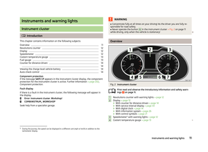 14
14 15
15 16
16 17
17 18
18 19
19 20
20 21
21 22
22 23
23 24
24 25
25 26
26 27
27 28
28 29
29 30
30 31
31 32
32 33
33 34
34 35
35 36
36 37
37 38
38 39
39 40
40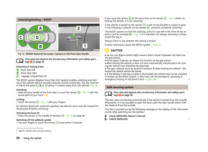 41
41 42
42 43
43 44
44 45
45 46
46 47
47 48
48 49
49 50
50 51
51 52
52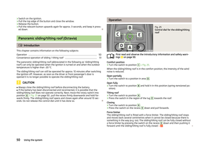 53
53 54
54 55
55 56
56 57
57 58
58 59
59 60
60 61
61 62
62 63
63 64
64 65
65 66
66 67
67 68
68 69
69 70
70 71
71 72
72 73
73 74
74 75
75 76
76 77
77 78
78 79
79 80
80 81
81 82
82 83
83 84
84 85
85 86
86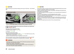 87
87 88
88 89
89 90
90 91
91 92
92 93
93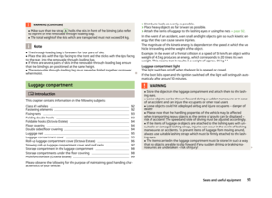 94
94 95
95 96
96 97
97 98
98 99
99 100
100 101
101 102
102 103
103 104
104 105
105 106
106 107
107 108
108 109
109 110
110 111
111 112
112 113
113 114
114 115
115 116
116 117
117 118
118 119
119 120
120 121
121 122
122 123
123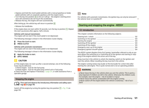 124
124 125
125 126
126 127
127 128
128 129
129 130
130 131
131 132
132 133
133 134
134 135
135 136
136 137
137 138
138 139
139 140
140 141
141 142
142 143
143 144
144 145
145 146
146 147
147 148
148 149
149 150
150 151
151 152
152 153
153 154
154 155
155 156
156 157
157 158
158 159
159 160
160 161
161 162
162 163
163 164
164 165
165 166
166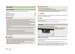 167
167 168
168 169
169 170
170 171
171 172
172 173
173 174
174 175
175 176
176 177
177 178
178 179
179 180
180 181
181 182
182 183
183 184
184 185
185 186
186 187
187 188
188 189
189 190
190 191
191 192
192 193
193 194
194 195
195 196
196 197
197 198
198 199
199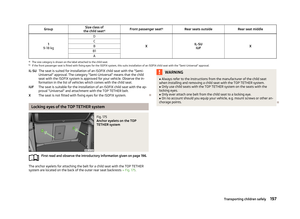 200
200 201
201 202
202 203
203 204
204 205
205 206
206 207
207 208
208 209
209 210
210 211
211 212
212 213
213 214
214 215
215 216
216 217
217 218
218 219
219 220
220 221
221 222
222 223
223 224
224 225
225 226
226 227
227 228
228 229
229 230
230 231
231 232
232 233
233 234
234 235
235 236
236 237
237 238
238 239
239 240
240 241
241 242
242 243
243 244
244 245
245 246
246 247
247 248
248 249
249 250
250 251
251 252
252 253
253 254
254 255
255 256
256 257
257 258
258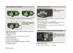 259
259 260
260 261
261 262
262 263
263 264
264 265
265 266
266 267
267 268
268 269
269 270
270 271
271 272
272 273
273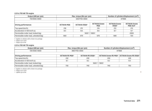 274
274 275
275 276
276 277
277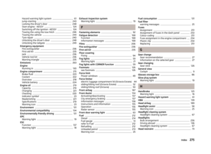 278
278 279
279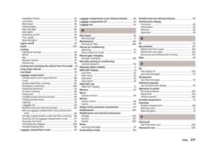 280
280 281
281 282
282 283
283 284
284 285
285 286
286