Page 9 of 262
Page 10 of 262
8 Cockpit
Cockpit
General illustration
Fig. l Cockp it: left sect io n
Fig . 2 Co ck pi t: r ig ht sect io n
Page 11 of 262

(!) Power window switches
@
®
©
Door handle
Power locking sw itch
Adjuster control for outside mir- rors ... . ............. .... .
® Air outlets ............... . .
@ Light switch . ... .... ... .. .. .
(J) Turn signa l and high beam . .. .
@ Mu ltifunction stee ring wheel
with:
- Horn
- Drive r's ai rbag .... ... .. .. .
- Shift buttons ..... ... .. .. .
® Instrument cluster
@ Sw itches for
- Windshield wiper/washer
- Menu disp lay ..... ... .. .. .
39
36
47
68
4 2
44
1 12
84
10
48
24
- T rip computer . . . . . . . . . . . . . 23
© Steering lock/ignition/starter
switch (in the steering wheel
column) . . . . . . . . . . . . . . . . . . . 71
@ Adjustab le s teer ing column . . . 71
@ Cruise control . . . . . . . . . . . . . . 76
€3J H ood re lease . . . . . . . . . . . . . . . 180
@ Data L ink Connector (DLC) for
On Board Diagnostics ( OBD II) 30
@ Instrument lighting . . . . . . . . . 46
@ Switches for
- Fuel filler flap release 178
- Rea r lid re lease . . . . . . . . . . . . 3 7
@ Depending on opt ions: Rad io or
nav igat ion system
@ Glove compar tment ( lockable) 6 4
@ Front passenger's a irbag . . . . . 112
@ Rear window defogger sw itch 70
@ C limate controls . . . . . . . . . . . . 6 6
@ Ashtray w ith cigarette lighter . . 62
@ Selecto r l ever o r gears hift lever
- Se lector lever (S tronic) . . . . . 80
- Gearsh ift leve r
@ Switches for
- Audi magnet ic r ide or Sport 80
mode . . . . . . . . . . . . . . . . . . . . 78, 78
Cockpi t 9
- Electron ic Stabilization Con -
trol . . . . . . . . . . . . . . . . . . . . . 150
- Emergency flasher . . . . . . . . . 45
- Ret ractable rear spo iler . . . . . 153
@ Parking brake lever . . . . . . . . . . 7 3
@ Cup holde r .. . . .. . . . . .. .. .. . 62
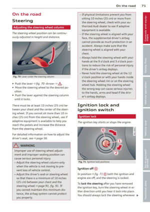
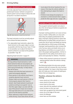
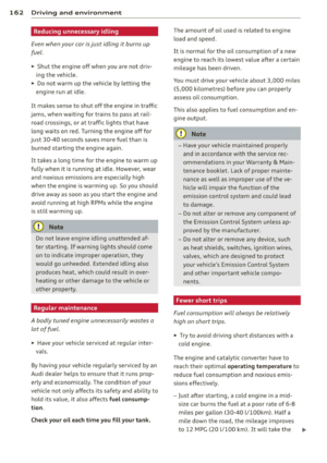
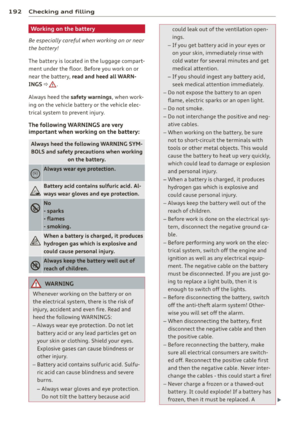
@ Tips
-Some of the equipment or features
show n in the genera l illustration may be
s tandard equ ipment on your vehicle or
may be opt ional equ ipment depending
on your model. A lways as k your author
ized Aud i de aler if you have a q ues tion
abou t your vehicle .
- A separate bro ch ure is p rov ided fo r yo ur
fac tory-i nstalled audio sys tem and/or
the A udi Nav igat ion System .
Page 12 of 262

10 Instruments and warning/indicator lights
Instruments and warning/indicator Lights
Instruments
Instrument cluster and controls
The instrument cluster is your central source of information.
Fig. 3 Overv iew of the inst rument cluster
(D Tachometer with time and date
dis play .. .... ..... ........ .
@ Coolant temperature gauge .. .
® Fuel gauge ................ .
© Speedometer with odometer ..
® Set/Check button ..... ... .. .
@ Driver information display
(?) Reset button for
- Trip odometer .......... .. .
- Service indicator
@ Tips
10 ,11
11
12
12
11
22
12
28
- When switching the ignition on, the nee
dles in the instrument cluster move up
ward briefly.
- The illumination for the instrument clus
ter lights up whenever you switch on the
i gnition with the
vehicle headlights off .
As the daylight fades, the instrument
cluster illumination likewise dims auto
matically a nd will go out completely
when the outside light is very low. This
feature is meant to remind you to switch
on the head lights when outside light
conditions become poor .
Tachometer (engine rev counter)
The tachometer indicates the engine RPM
(revolutions per minutes) .
en 0
~
~
"'
If engine RPM drops below 1,500, you should
downshift to the next lower gear. The red area
at the end of the scale indicates maximum
permissible engine RPM after the br eak-in pe
riod. Before reaching this area, move these
lector lever to position "D (Drive)" or ease
your foot off the acce lerator pedal.
(D Note
The tachometer needle should only briefly
be in the red zone: you could damage your
engine! The beg inning of the red zone var
i es depending on the engine.
@ For the sake of the environment
Upshifting early saves fuel and reduces en
gine noise.
Page 13 of 262

Instrument s and warning /indicator lights 11
Digital clock with date display
Your vehicle is equipped with a quartz con
trolled digital clock .
Fig. 4 In str um en t cl uste r w it h t he dig ita l cloc k
To set the hour
.. Pu ll t he knob (hour d isp lay flashes) and
tu rn it t o the left or rig ht.
To set the minutes
.. Pull the knob as ma ny times as necessary
un til the mi nute display flash es.
.. Turn the knob to the left or r ight .
To set the date
.. Pull the knob as many times as necessary
until the day, month or year display flashes.
.. Turn the knob to the left or right .
To hide or d isplay the d ate
.. Pull the knob as many times as necessary
unti l the date display flashes.
.. Turn the knob to t he left or r ight.
When the date disp lay stops blinking, this
means the time and date have been success
fu lly stored.
W ith the ignition off, pushing or pulling the
Set/Check button¢
page 10, fig . 3@ can
turn on the dis play f ie ld lighting for a few sec
onds .
Engine coolant temperature gauge
The engine coo la nt gauge ¢ page 10 , fig. 3@
only works when the ign ition is on. To prevent
damage to your e ngine, please note the fo l
l owing important points:
Engine cold
As long as the nee dle rem ains a t the left end
of the gauge, the engine s till h as not reac hed
its operating temperat ure. Avoid high engine
speeds, heavy engine loads and heavy throt
tle.
Normal temperature
W hen the engine has re ache d its ope rat ing
temperature, the need le w ill move into the
mid dle of t he gauge and rema in there .
If the
engine is working hard at high outside tem
peratures, the needle may turn fu rther to the
right. This is no cause for concern as long as
the . warni ng lig ht in the inst rument cl uster
does not illuminate .
When the. war ning light starts to flash,
th is can mean one of two thi ngs: either the
coolant
temperature is too high, o r the coo l
ant
level is too low ¢ page 16 .
A WARNING
--Always obs erv e th e warn ing in
¢ page 1 7 4, Engine compar tment be
fore opening the eng ine ho od and check
in g the eng ine coolan t leve l.
- N ever open t he eng ine hood if you see or
he ar ste am, or if you see engi ne coo lant
drippi ng from t he en gine compar tment .
You could bur n yourse lf . Let the en gin e
coo l off fi rst u ntil yo u can n o longe r see
or hear steam or coolant escap ing.
(D Note
- M ounting ad ditiona l lights or accessories
i n fr ont of the air inlets reduces the coo l
ing effect of t he radiato r. At high o utsi de
tempe rat ures or h igh engine load, the
eng ine could overheat.
- The front spoiler has been designed to
properly d istribute the cooling a ir when
the vehicl e is movi ng. If the spoiler is
damaged, this c ould reduce the coo ling
e ff ect a nd th e eng ine could then ove r
h eat . As k yo ur au thori zed A udi deal er for
a ssis tan ce.
Page 14 of 262

12 Instruments and warning/indicator lights
Fuel gauge
The fuel gauge works only when the ignition is
on . When the needle reaches the red area, the
warning light in the instrument cluster will il
luminate ¢
page 20 00']. Time to refuel!
(D Note
Never run the tank completely dry! An ir
regular supply of fue l can cause eng ine
misfiring and fuel could enter into the ex
haust system. The catalytic converter
could then overheat and be damaged.
Speedometer with odometer
The speedometer shows you the vehicle
speed , and the odometer shows you how
many miles (kilometers) you have driven.
Fig. S Speedomete r close -up: odomete r display
The distance driven is shown in miles (USA
models) or in kilometers (Canada models).
lower odometer
The lower odometer shows the total number
of miles (kilometers) driven.
Upper odometer (trip odometer)
The upper odometer shows the tota l number
of mi les (kilometers) driven since you last re
set the odometer back to zero . You can use
this odometer when you want to keep track of how many miles (kilometers) you have driven
for a single trip or errand. The last digit indi
cates 1/10 of a mile (100 meters) . You can set
the trip odometer back to zero by pressing the
reset button
¢fig. 5.
With the ignition off, pushing of the Set/
Check button ¢
page 10, fig. 3@ can turn on
the display fie ld lighting for a few seconds.
Malfunction message
If there is a malfunction somewhere in the in
strument cluster,
dEF w ill appear in the trip
odometer and will stay on . Contact your au
thorized Audi dea ler to have the prob lem cor
rected.
Immobilizer
When the ignition is sw itched on, the data on
the ignition key are scanned automat ica lly.
If an unauthor ized key was used,
SAFE is dis
played continuously in the odometer display
field . The vehicle cannot be operated
¢ page 33.
Warning/indicator
Lights
Description
The indicator lights in the instrument cluster
blink or turn on. They indicate functions or
malfunctions ¢.& .
Messages may appear with some indicator
li ghts. The messages turn off after a sho rt
time. To display a message again, press the
Set/Check button¢
page 10, fig. 3@ . If
there is more than one malfunction, the indi
cator lights will turn on one after the other for
approximately two seconds each.
Some indicators lights in the display can turn
on in severa l co lors.
A WARNING
- Failure to heed warning lights and other
important vehicle information may result
in ser ious personal injury or vehicle dam
age.
- Whenever stalled or stopped for repair,
move the vehicle a safe distance
off the
road, stop the engi ne, and turn on the
emergency flasher¢
page 45.
Page 15 of 262

Instrument s and warnin g/indic ator ligh ts 13
-The engine compartment of any motor
vehicle is a potentially hazardous area.
Before you check anything in the engine
compartment, stop the engine and let it
cool down. Always exercise extreme cau
t ion when working under the hood
¢ page 174, Engine compartment
(D Tips
Malfunctions or faults w ill be identified e i
ther with a red symbol (pr iority 1 -Dan
ger!) or with a yellow symbol (pr iority 2 -
Warn ing).
Overview
Some ind icator lights tu rn on briefly to che ck
the func tion of that system when yo u switch
the ignition on. These systems are marked
with a./ in the following tables. If one of
these ind icator lights does not turn on, there
is a malfunction in that system.
R ed indicator lights
Red symbols indica te a priority malfunction -
Danger!
- Pull
off the road.
- Stop the vehicle.
- Turn
off the engine.
- Check the ma lfunction ing system. Contact
your authorized Aud i dea ler or a qualified
workshop for assistance .
-USA models: Malf u nction in the
brake system
¢ page 14
D
D
Canada models : Malfunction in the
brake system
¢ page 1 4
USA models : Airbag system./
¢page 15
Canada models: Airbag system./
¢page 15
Safety belt
¢page 16
Generator ./
¢page 16 Engine o
il pressure too low
¢ page 16
Engine coolant level too low/
engine coolant tempe rature too
h igh
¢ page 16
Electro -mechanical power assist
¢ page 17
Clutch is overheating
¢page85
Yellow indicator light s
Yellow symbo ls indicate a priority 2 malfunc
tion -Warning!
Ji]
I
Clutch pedal
¢page 17
Electronic Stabilization Control (ESC)
./ ¢page 17
Electron ic Stabilisat ion Control (ESC)
./ ¢page 17
~ USA models: anti-lock brake system
~(ABS)./ defective ¢page 18
•
Canada models : anti-lock brake sys
tem (ABS) ./ defective
¢ page 18
Worn brake pads
¢page 18
Tire pressure too low
¢page 214
Tire pressure monitoring system ¢page 215
--~
~ Electron ic powe r control./
~ ¢page19
~ USA models: Malfunctio n Indicator
Bil Lamp (MIL) ¢page 19
11'!!1 Canada models : Malfunction Indica
mil to r Lamp (MIL) ¢page 19
Engine speed limitation*
¢page 19
Page 16 of 262

14 Instrum ent s and w arn ing /indic ato r light s
11111 Check engine oil leve l
lill C?page19
111!!1111 Engine oil sensor malfunction
liflll¢page19
Battery voltage too high or too low
C?page 19
Low fuel level
¢page 20
• Windsh
ield washer fluid level low ¢ page20
J:J
Defective light bulb
¢page 20
•
USA model s: Defective brake light
¢ page 20
II
Canada model s: Defective brake
light¢
page 20
II
Dynamic headlight range control*
defective ¢
page 20
Ill
Adaptive Light* defective
¢page20
m
Light/rain sensor defective (automat-
ic headlights)* defective¢
page 21
B
Audi magnetic ride
¢page 21
fJ
Rear spoiler./
¢ page 21
•
USA model s: Speed warning 1
¢page 74
~
Canada mod els : Speed warning 1
¢ page 74
•
USA models: Speed warning 2
¢page 74
•
Canad a model s: Speed warning 2
¢ page 74
~£1
Electro-mechanical power assist
¢page 17
Other indi cato r ligh ts
II
II
RUI E
•
•
Turn s ignals
¢ page 21
USA models: Cruise control acti
vated ¢
page 21
Canada model s: Cruise control
act ivated ¢
page 21
]!High beam
IIC?page44
BRAKE/ ((D) Brake system
This warning/indicator Light illuminates when
the brake fluid level is too low or when there
is a malfunction in the ABS, or when the park
ing brake is set.
If the - (USA models)/ . (Canada
models) symbo l flashes in the display with the
parking brake released, there is a malfunction
in the brake system . In addition to the sym
bol, one of two messages appears in the dis
play:
Stop veh icle and chec k bra ke fl uid le vel
Stab ilization pr ogram and AB S fau lt! See
O wne r's man ual
"' Pull off the road and stop the veh icle .
"' Obta in profess ional assistance.
USA models: if there is a malfunct ion in the
ABS system, the
11:S warning/ind icator light
i lluminates along with the -system
malfunction warning/indicator light¢,&. .
Canada models: if there is a malfunction in
the ABS system , the
tlJ warning/indicator
li ght illum inates together with the. brake
system malfunction warn ing/indicato r light
¢ .&. .
The light 1111 (USA)/ . (Canada) illum i-
nates when the ignition is turned on.
It goes
out afte r the eng ine has been sta rted and the
parking brake is fully re leased. This indicates ..,.