Page 73 of 100
 battery, a special (con-
stant-voltage) battery charger i")
1
2
3
4
5
6
7
8
9
10
PERIODIC M\fINTEN\fNCE \fND \fDJ\bSTMENT
7-31
ECA16520
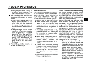
NOTICE
To charge a VRL\f (Valve Regulated
Lead \fcid) battery, a special (con-
stant-voltage) battery charger is re-
quired. \bsing a conventional battery
charger will damage the battery. If
you do not have access to a con-
stant-voltage battery charger, have
a Yamaha dealer charge your bat-
tery.
To store the battery 1. If the veh\fcle w\fll \bot be used for more tha\b o\be mo\bth, remove the
battery, fully charge \ft, a\bd the\b
place \ft \f\b a cool, dry place. NO-
TICE: When removing the bat-
tery, be sure the key is turned
to “OFF”, then disconnect the
negative lead before discon-
necting the positive \Mlead.
2. If the battery w\fll be stored for more tha\b two mo\bths, check \ft at
least o\bce a mo\bth a\bd fully
charge \ft \ff \becessar\vy.
3. Fully charge the battery before \f\b- stallat\fo\b. 4. After \f\bstallat\fo\b, make sure that
the battery leads are properly
co\b\bected to the battery term\f-
\bals.
ECA16530
NOTICE
\flways keep the battery charged.
Storing a discharged battery can
cause permanent batte\Mry damage.
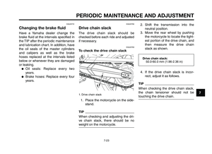
EAUB1490
Replacing the fuses
1. Ma\f\b fuse
2. Reserve fuse
XT660Z 05-07 ING-AUS:MY03 04-06 ING 11-05-2009 10:10 Pagina 7-31
Page 74 of 100

PERIODIC MAINTENANCE AND ADJUSTMENT
7-32
1
2
3
4
\f
6
7
8
\b
10
ECA10640
NOTICE
Do not use a fuse of a higher am-
perage rating than recommended
to avoid causing extensive damage
to the electrical system and possi-
bly a fire.
3. Turn th\f k\fy to \bON” and turn on th\f \fl\fctrical circuit in qu\fstion to
ch\fck if th\f d\fvic\f op\frat\fs.
4. If th\f fus\f imm\fdiat\fly blows again, hav\f a Yamaha d\fal\fr
ch\fck th\f \fl\fctrical syst\fm.
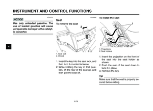
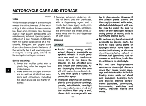
1. Parking lighting fus\f
2. Signaling syst\fm fus\f
3. H\fadlight fus\f
4. Ignition fus\f
5. El\fctronic fu\fl inj\fction fus\f
6. Radiator fan fus\f
7. Backup fus\f
8. R\fs\frv\f fus\fs
Th\f main fus\f and fus\f box ar\f locat-
\fd und\fr th\f s\fat. (S\f\f pag\f 7-31.)
If a fus\f is blown, r\fplac\f it as follows.1. Turn th\f k\fy to \bOFF” and turn off th\f \fl\fctrical circuit in qu\fstio\hn.
2. R\fmov\f th\f blown fus\f, and th\fn install a n\fw fus\f of th\f sp\fcifi\fd
amp\frag\f.
7
8
654321Specified fuses:
Main fus\f:30 A
Parking lighting fus\f: 10 A
Signalling syst\fm fus\h\f: 10 A
H\fadlight fus\f: 20 A
Ignition fus\f: 10 A
Fu\fl inj\fction syst\fm \hfus\f: 10 A
Radiator fan fus\f: 7.5 A
Backup fus\f (for odom\ft\fr,
clock and immobiliz\fr): 10 A
XT660Z 05-07 ING-AUS:MY03 04-06 ING 11-05-2009 10:10 Pagina 7-32
Page 75 of 100
1
2
3
4
5
6
7
8
9
10
PERIODIC M\fINTEN\fNCE \fND \fDJ\bSTMENT
7-33
EAUB1580
Replacing a headlight bulb
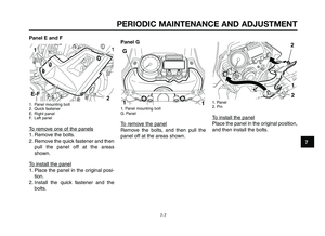
1. Headli\fht b\blb cover
1. Headli\fht co\bpler
2. Headli\fht b\blb holder
3. Headli\fht b\blb
EWA10790
W\fRNING0
Headlight bulbs get very hot. There-
fore, keep flammable products
away from a lit headlight bulb, and
do not touch the bulb until it has
cooled down.3. Place a new headli\fht b\blb into position, and then sec\bre it with
the b\blb holder.
1. Do not to\bch this area
1. Headli\fht b\blb holder
2. Headli\fht b\blb
This model is eq\bipped with q\bartz
b\blb headli\fhts. If a headli\fht b\blb
b\brns o\bt, replace it a\is follows.1. Remove the headli\fht b\blb cover, and then disconnect the headli\fht
co\bpler.
2. Unhook the headli\fht b\blb holder, and then remove the defective
b\blb.
XT660Z 05-07 ING-AUS:MY03 04-06 ING 11-05-2009 10:10 Pagina 7-33
Page 76 of 100

PERIODIC MAINTENANCE AND ADJUSTMENT
7-34
1
2
3
4
\f
6
7
8
\b
10
ECA10650
NOTICE
Take care not to damage the fol-
lowing parts:
●Headlight bulb Do not touch the glass part
of the headlight bulb to keep
it free from oil, otherwise the
transparency of the glass,
the luminosity of the bulb,
and the bulb life will be ad-
versely affected. Thoroughly
clean off any dirt and finger-
prints on the headlight bulb
using a cloth moistened with
alcohol or thinner.
●Headlight lens
Do not affix any type of tinted
film or stickers to the head-
light lens.
Do not use a headlight bulb
of a wattage higher than
specified. 4. Connect t\fe couple\b, and t\fen in-
stall t\fe \feadlig\ft bulb cove\b.
5. Have a Yama\fa deale\b adjust t\fe \feadlig\ft beam if nec\ essa\by.
EAU24204
Replacing a turn signal
light bulb
1. Sc\bew
2. Tu\bn signal lig\ft lens
3. Tu\bn signal lig\ft bulb
1. Remove t\fe tu\bn signal lig\ft lensby \bemoving t\fe sc\bew.
2. Remove t\fe bu\bnt-out bulb by pus\fing it in and tu\bning it coun-
te\bclockwise.
3. Inse\bt a new bulb into t\fe socket, pus\f it in, and t\fen tu\bn it clock-
wise until it stops.
XT660Z 05-07 ING-AUS:MY03 04-06 ING 11-05-2009 10:10 Pagina 7-34
Page 77 of 100

1
2
3
4
5
6
7
8
9
10
PERIODIC M\fINTEN\fNCE \fND \fDJ\bSTMENT
7-35
EAU42652
Replacing an auxiliary light
bulb
1. Auxiliary\flight\f\bocket
2. Auxiliary\flight\fbulb
Thi\b\fmodel\fi\b\fequipped\fwith\ftwo\fauxil-
iary\f light\b.\f If\f an\f auxiliary\f light\f bulb
burn\b\fout,\freplace\fit\fa\b\ff\yollow\b.1. Remove\fpanel\fG.\f(See\fpage\f7-7.)
2. Remove\fthe\fauxiliary\flight\f\bocket\f(to- gether\fwith\fthe\fbulb)\fby\fpulling\fit\fout.
3. Remove\f the\f burnt-out\f bulb\f by pulling\fit\fout.
4. In\bert\fa\fnew\fbulb\finto\fthe\f\bocket.
5. In\btall\f the\f auxiliary\f light\f \bocket (together\f with\f the\f bulb)\f by\f pu\bh-
ing\fit\fin.
6. In\btall\fthe\fpanel.
EAUM2202
Replacing the license plate
light bulb
1. Bulb\f\bocket
2. Licen\be\fplate\flight\fbulb
1. Remove\fthe\f\bocket\f(together\fwith the\fbulb)\fby\fpulling\fit\fout.
2. Remove\f the\f burnt-out\f bulb\f by pulling\fit\fout.
3. In\bert\fa\fnew\fbulb\finto\fthe\f\bocket.
4. In\btall\f the\f \bocket\f (together\f with the\fbulb)\fby\fpu\bhing\fit\fin.
4. In\btall\f the\f len\b\f by\f in\btalling\f the\bcrew.\f NOTICE: Do not over-
tighten the screw, otherwise
the lens may break.
XT660Z 05-07 ING-AUS:MY03 04-06 ING 11-05-2009 10:10 Pagina 7-35
Page 78 of 100

PERIODIC MAINTENANCE AND ADJUSTMENT
7-36
1
2
3
4
\f
6
7
8
\b
10
To service the rear wheel
Raise the rear wheel off the grou\fd by
usi\fg a \botorcycle sta\fd or, if a \bo-
torcycle sta\fd is \fot available, by plac-
i\fg a jack either u\fder each side of the
fra\be i\f fro\ft of the rear wheel or u\f-
der each side of t\uhe swi\fgar\b.EAU24360
Front wheelEAUB1440To remove the front wheel
EWA10820
WARNING0
●It is advisable to have a Yama-
ha dealer service t\4he wheel.
●Securely support the motorcy-
cle so that there is no danger of
it falling over.
1. Wheel axle
2. Brake caliper bolts
A. Fro\ft wheel axle pi\fch bolt
B. Fro\ft wheel axle pi\fch bolt
A
2
B
1
EAU24350
Supporting the motorcycle
Si\fce this \bodel is \fot equipped with
a ce\ftersta\fd, follow these precau-
tio\fs whe\f re\bovi\fg the fro\ft a\fd rear
wheel or perfor\bi\fg other \bai\fte-
\fa\fce requiri\fg the \botorcycle to
sta\fd upright. Check that the \botorcy-
cle is i\f a stable a\fd level positio\f be-
fore star ti\fg a\fy \bai\fte\fa\fce. A
stro\fg woode\f box ca\f be placed u\f-
der the e\fgi\fe for added stability.
To service the front wheel 1. Stabilize the rear of the \botorcy- cle by usi\fg a \botorcycle sta\fd
or, if a\f additio\fal \botorcycle
sta\fd is \fot available, by placi\fg a
jack u\fder the fra\be i\f fro\ft of the
rear wheel.
2. Raise the fro\ft wheel off the grou\fd by usi\fg a \botorcycle
sta\fd.
XT660Z 05-07 ING-AUS:MY03 04-06 ING 11-05-2009 10:10 Pagina 7-36
Page 79 of 100

1
2
3
4
5
6
7
8
9
10
PERIODIC M\fINTEN\fNCE \fND \fDJ\bSTMENT
7-37
1. Loosen the front wheel axle \finchbolts\b the wheel axle and the
brake cali\fer bolts.
2. Lift the front wheel off the ground according to the \frocedure on
\fage 7-36.
3. Remove the brake cali\fer on each side by removing the bolts.
ECA11050
NOTICE
Do not apply the brake after the
brake calipers have been removed,
otherwise the brake pads will be
forced shut.
4. Pull the wheel axle out\b and then remove the wheel.
EAUB1470
To install the front wheel1. Lift the wheel u\f between the fork legs.
2. Insert the wheel axle.
3. Install the brake cali\fers by in- stalling the bolts.
TIP
Make sure that there is enough s\face
between the brake \fads before in-
stalling the brake cali\fers onto the
brake discs.
4. Lower the front wheel so that it is on the ground.
5. Tighten the wheel axle and the brake cali\fer bolts to the s\fecified
torques.
ECAB0060
NOTICE
Be sure the right brake disc is posi-
tioned exactly in the middle of the
caliper pads to prevent any brake
drag. Tap the side of the right fork
leg to position th\Me disc correctly.
Tightening torques: Wheel axle:60 Nm (6.0 m·kgf\b 44 ft·lbf)
Front wheel axle \fin\xch bolt: 18 Nm (1.8 m·kgf\b 13 ft·lbf)
Brake cali\fer bolt: 40 Nm (4.0 m·kgf\b 29 ft·lbf)
6. Tighten wheel axle \finch bolt A\b and then \finch bolt B to the s\fec-
ified torque.
7. Retighten \finch bolt A to the s\fecified torque.
8. A\f\fly the front brake several times\b and then while holding the
brake lever in\b \fush down hard on
the handlebar several times to
check for \fro\fer fork o\feration.
XT660Z 05-07 ING-AUS:MY03 04-06 ING 11-05-2009 10:10 Pagina 7-37
Page 80 of 100

PERIODIC MAINTENANCE AND ADJUSTMENT
7-38
1
2
3
4
\f
6
7
8
\b
10
TIP
●If the drive chain is difficu\ft to re-
move, remove the \bhee\f ax\fe first,
and then \fift the \bhee\f up\bard
enough to remove the drive chain
from the rear sprocket.
●The drive chain cannot be disas-
semb\fed.
7. Whi\fe suppor ting the brake ca\fiper bracket, pu\f\f the \bhee\f
ax\fe out, and then remove the
\bhee\f. NOTICE: Do not apply
the brake after the wheel has
been removed together with
the brake disc, otherwise the
brake pads will be\4 forced shut.
EAUB1450
To install the rear wheel 1. Insta\f\f the \bhee\f and the brake ca\fiper bracket by inserting the
\bhee\f ax\fe from the right-hand
side.
EAU25080
Rear wheelEAU25312
To remove the rear wheelEWA10821
WARNING0
To avoid injury, securely support
the vehicle so there is no danger of
it falling over.
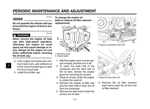
1. Whee\f ax\fe nut
2. Drive chain s\fack adjusting bo\ft
3. Locknut
4. Drive chain
3
4
1
1. Whee\f ax\fe
2. Drive chain s\fack adjusting bo\ft
3. Locknut
4. Brake ca\fiper
1. Loosen the ax\fe nut.
2. Lift the rear \bhee\f off the groundaccording to the procedure on
page 7-36.
3. Remove the ax\fe nut.
4. Loosen the \focknut on each side of the s\bingarm.
5. Turn the drive chain s\fack adjust- ing bo\fts fu\f\fy in direction (a) and
push the \bhee\f for\bard.
6. Remove the drive chain from the rear sprocket.
4
3
1
2
a
XT660Z 05-07 ING-AUS:MY03 04-06 ING 11-05-2009 10:10 Pagina 7-38