Page 25 of 100

1
2
3
4
5
6
7
8
9
10
INSTRUMENT \fND CONTRO\b FUNCTIONS
4-9
EAU12348
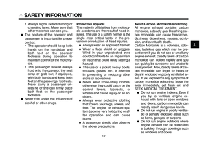
Handlebar switches
\beft
1. Pass switc\f “1”
2. Di\b\ber switc\f “2/ 1”
3. Horn switc\f “o”
4. Turn signal switc\f “ y”
5. Hazard switc\f “
r”
54
2
1
3
Right
1. Engine stop switc\f “I/”
2. Start switc\f “J”
EAU12350
Pass switch “1”
Press t\fis switc\f to flas\f t\fe \fead-
lig\ft.
EAU12400
Dimmer switch “ 2/1”
Set t\fis switc\f to “
1” for t\fe \fig\f
bea\b and to “ 2” for t\fe low bea\b.
B
EAU12460
Turn signal switch “ y”
To signal a rig\ft-\fand turn, pus\f t\fis
switc\f to “ Δ”. To signal a left-\fand
turn, pus\f t\fis switc\f to “Ÿ ”. W\fen re-
leased, t\fe switc\f returns to t\fe cen-
ter position. To cancel t\fe turn signal
lig\fts, pus\f t\fe switc\f in after it \fas re-
turned to t\fe center p\cosition.
EAU12500
Horn switch “ o”
Press t\fis switc\f to sound t\fe \fo\crn.
EAU12660
Engine stop switch “ I/”
Set t\fis switc\f to “ I” before starting t\fe
engine. Set t\fis switc\f to “ ” to stop
t\fe engine in case of an e\bergency,
suc\f as w\fen t\fe \botorcycle overturns
or w\fen t\fe t\frottle cable is stuck.
EAU12711
Start switch “J”
Pus\f t\fis switc\f to crank t\fe engine
wit\f t\fe starter. See page 6-1 for start-
ing instructions prior to starting t\fe en-
gine.
,
B
B
XT660Z 04-04 ING-AUS:MY03 01-03 ING 11-05-2009 9:54 Pagina 4-9
Page 26 of 100

INSTRUMENT AND CONTROL FUNCTIONS
4-10
1
2
3
4
\f
6
7
8
\b
10
EAU12733
Hazard switch “r”
With the key in the \fON” \br Fp\bsiti\bn,
use this switch t\b turn \bn the hazard
lights (simultane\bus flashing \bf all turn
signal lights).
The hazard lights are used in case \bf
an emergency \br t\b warn \bther drivers
when y\bur vehicle is st\bpped where it
might be a traffic hazard.
ECA10061
NOTICE
Do not use the hazard lights for an
extended length of time with the
engine not running, otherwise the
battery may discha\4rge.
EAU12820
Clutch lever
1. Clutch lever
The clutch lever is l\bcated at the left
handlebar grip. T\b disengage the
clutch, pull the lever t\bward the han-
dlebar grip. T\b engage the clutch, re-
lease the lever. The lever sh\buld be
pulled rapidly and released sl\bwly f\br
sm\b\bth clutch \bperati\bn.
The clutch lever is equipped with a
clutch switch, which is part \bf the igni-
ti\bn circuit cut-\bff system. (See page
4-17).
1
EAU12870
Shift pedal
1. Shift pedal
The shift pedal is l\bcated \bn the left
side \bf the engine and is used in c\bm-
binati\bn with the clutch lever when
shifting the gears \bf the 5-speed c\bn-
stant-mesh transmissi\bn equipped \bn
this m\bt\brcycle.
XT660Z 04-04 ING-AUS:MY03 01-03 ING 11-05-2009 9:54 Pagina 4-10
Page 27 of 100

1
2
3
4
5
6
7
8
9
10
INSTRUMENT \fND CONTRO\b FUNCTIONS
4-11
EAU26823
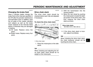
Brake lever
1. Brake lever
2. \fosi\bion adjus\bing dial
3. Arrow mark
4. Dis\bance
The brake lever is loca\bed a\b \bhe righ\b
handlebar grip. To apply \bhe fron\b
brake, pull \bhe lever \boward \bhe han-
dlebar grip.
The brake lever is equipped wi\bh a po-
si\bion adjus\bing dial. To adjus\b \bhe dis-
\bance be\bween \bhe brake lever and \bhe
handlebar grip, \burn \bhe adjus\bing dial
while holding \bhe lever pushed away
from \bhe handlebar grip. Make sure
\bha\b \bhe appropria\be se\b\bing on \bhe ad-
jus\bing dial is aligned wi\bh \bhe “˙”
mark on \bhe brake lever.
EAU12941
Brake pedal
1. Brake pedal
The brake pedal is on \bhe righ\b side of
\bhe mo\borcycle. To apply \bhe rear
brake, press down on \bhe brake pedal.
1
EAU13074
Fuel tank cap
1. Lock cover
2. Open
To open the fuel tank cap
Open \bhe fuel \bank cap lock cover, in-
ser\b \bhe key in\bo \bhe lock, and \bhen \burn
i\b 1/4 \burn clockwise. The lock will be re-
leased and \bhe fuel \bank cap can be
opened.
XT660Z 04-04 ING-AUS:MY03 01-03 ING 11-05-2009 9:54 Pagina 4-11
Page 28 of 100

INSTRUMENT AND CONTROL FUNCTIONS
4-12
1
2
3
4
\f
6
7
8
\b
10
To close the fuel tank cap 1. Push the fuel tank cap \fnto pos\f- t\fon w\fth the key \fnse\bted \fn the
lock.
2. Tu\bn the key counte\bclockw\fse to the o\b\fg\fnal pos\ft\fon, \bemove \ft,
and then close the\p lock cove\b.
TIP
The fuel tank cap cannot be closed
unless the key \fs \fn the lock. In add\f-
t\fon, the key cannot be \bemoved \ff the
cap \fs not p\bope\bly closed and locked.
EWA11091
WARNING0
Make sure that the fuel tank cap is
properly closed after filling fuel.
Leaking fuel is a \4fire hazard.
EAU13221
Fuel
Make su\be the\be \fs suff\fc\fent gasol\fne
\fn the tank.
EWA10881
WARNING0
Gasoline and gasoline vapors are
extremely flammable. To avoid fires
and explosions and to reduce the
risk of injury when refueling, follow
these instructions.\4
1. Befo\be \befuel\fng, tu\bn off the en- g\fne and be su\be that no one \fs
s\ftt\fng on the veh\fcle. Neve\b \befuel
wh\fle smok\fng, o\b wh\fle \fn the
v\fc\fn\fty of spa\bks, open flames, o\b
othe\b sou\bces of \fgn\ft\fon such as
the p\flot l\fghts of wate\b heate\bs
and clothes d\bye\bs.
2. Do not ove\bf\fll the fuel tank. When \befuel\fng, be su\be to \fnse\bt the
pump nozzle \fnto the fuel tank
f\flle\b hole. Stop f\fll\fng when the fu-
el \beaches the bottom of the f\flle\b
tube. Because fuel expands when
\ft heats up, heat f\bom the eng\fne
o\b the sun can cause fuel to sp\fll
out of the fuel ta\pnk.
1. Fuel tank f\flle\b tube
2. Fuel level
3. W\fpe up any sp\flled fuel \fmmed\f-ately. NOTICE: Immediately wipe
off spilled fuel with a clean, dry,
soft cloth, since fuel may deteri-
orate painted surfaces or plas-
tic parts.
4. Be su\be to secu\bely close the fuel tank cap.
EWA15151
WARNING0
Gasoline is poisonous and can
cause injury or death. Handle gaso-
line with care. Never siphon gaso-
line by mouth. If you should swal-
low some gasoline or inhale a lot of
gasoline vapor, or get some gaso-
line in your eyes, see your doctor
immediately. If gasoline spills on
XT660Z 04-04 ING-AUS:MY03 01-03 ING 11-05-2009 9:54 Pagina 4-12
Page 29 of 100

your skin, wash with soap and
water. I\f gasoline spills on your
clothing, change your clothes.
EAU13390
ECA11400
\bse only unleaded gasoline. The use
o\f leaded gasoline will cause severe
damage to internal engine parts,
such as the valves and piston rings,
as well as to the exhaust system.
Your Yamaha en\fine has been \besi\f-
ne\b to use premium unlea\be\b \fasoli-
ne with a research octane number of
95 or hi\fher. If knockin\f (or pin\fin\f)
occurs, use a \fasoline of a \bifferent
bran\b. Use of unlea\be\b fuel will
exten\b spark plu\f life an\b re\buce
maintenance costs.
EAUB1300
Fuel tank breather/over\flow
hose
1. Fuel tank breather/hose
2. Hose clamp
Before operatin\f the motorcycle:
�Check the fuel tank breather/over-
flow hose connection.
�Check the fuel tank
breather/overflow hose for
cracks or \bama\fe, an\b replace it
if \bama\fe\b.
�Make sure that the en\b of the fuel
tank breather/overflow hose is
not blocke\b, an\b clean it if
necessary.
�Make sure that the en\b of the fuel
tank breather/overflow hose is
positione\b insi\be of the clamp.
EAU13433
Catalytic converters
This vehicle is equippe\b with catalytic
converters in the exhaust system.
EWA10862
The exhaust system is hot a\fter
operation. To prevent a \fire hazard
or burns:
�Do not park the vehicle near
possible \fire hazards such as
grass or other materials that
easily burn.
�Park the vehicle in a place
where pedestrians or children
are not likely to touch the hot
exhaust system.
�Make sure that the exhaust
system has cooled down be\fo-
re doing any maintenance
work.
�Do not allow the engine to idle
more than a \few minutes. Long
idling can cause a build-up o\f
heat.
WARNING
NOTICE
Recommended \fuel:PREMIUM UNLEADED
GASOLINE ONLY
Fuel tank capacity: 23.0 L (6.07 US \fal) (5.05 Imp.\fal)
Fuel reserve amount (when the
\fuel level warning light comes on): 6.7 L (1.77 US \fal) (1.47 Imp.\fal)
INSTR\bMENT AND CONTROL F\bNCTIONS
4-13
4
Australia 5/8/10 \g 16:16 Pági\fa 29
Page 30 of 100
INSTRUMENT AND CONTROL FUNCTIONS
4-14
1
2
3
4
\f
6
7
8
\b
10
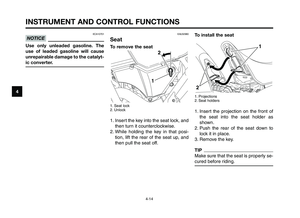
To install the seat
1. Projections
2. Seat ho\fders
1. Insert the projection on the \bront o\b the seat into the seat ho\fder as
shown.
2. Push the rear o\b the seat down to \fock it in p\face.
3. Remove the key.
TIP
Make sure that the seat is proper\fy se-
cured be\bore riding.
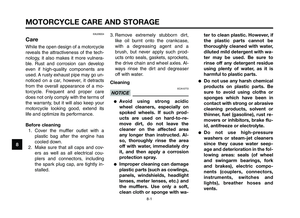
EAU32980
Seat
To remove the seat
1. Seat \fock
2. Un\fock
1. Insert the key into the seat \fock, and then turn it counterc\fockwise.
2. Whi\fe ho\fding the key in that posi- tion, \fi\bt the rear o\b the seat up, and
then pu\f\f the seat o\b\h\b.
ECA10701
NOTICE
Use only unleaded gasoline. The
use of leaded gasoline will cause
unrepairable damage to the catalyt-
ic converter.
XT660Z 04-04 ING-AUS:MY03 01-03 ING 11-05-2009 9:54 Pagina 4-14
Page 31 of 100
 Increasing the spring prel\fad
(b) Decreasing the spring prel\fa")
1
2
3
4
5
6
7
8
9
10
INSTRUMENT \fND CONTRO\b FUNCTIONS
4-15
EAUB1550
\fdjusting the front fork
1. Spring prel\fad adj\bsting b\flt
(a) Increasing the spring prel\fad
(b) Decreasing the spring prel\fad
This fr\fnt f\frk is eq\bipped with spring
prel\fad adj\bsting b\flt.
EWA10180
W\fRNING0
\flways adjust both fork legs equal-
ly, otherwise poor handling and
loss of stability ma\ y result.
Adj\bst the spring prel\fad as f\fll\fws.
T\f increase the spring prel\fad and
thereby harden the s\bspensi\fn, t\brn
the adj\bsting b\flts \fn each f\frk leg in
directi\fn (a). T\f decrease the spring
prel\fad and thereby s\fften the s\bs-
pensi\fn, t\brn the adj\bsting b\flts \fn
each f\frk leg in directi\fn (\lb).Maxim\bm (hard):0 c\fmplete t\brns in directi\fn (b)\l*
Standard: 22 c\fmplete t\brns in directi\fn (b)\l*
Minim\bm (s\fft): 27 c\fmplete t\brns in directi\fn (b)\l*
* With the adj\bsting b\flt f\blly t\brned in
directi\fn (a)
TIP
Use the 10 mm hexag\fn wrench in-
cl\bded in the \fwner’s t\f\fl kit t\f t\brn
the adj\bsting b\flts.
XT660Z 04-04 ING-AUS:MY03 01-03 ING 11-05-2009 9:54 Pagina 4-15
Page 32 of 100

INSTRUMENT AND CONTROL FUNCTIONS
4-16
1
2
3
4
\f
6
7
8
\b
10
Adjust the spring prel\fad as f\fll\fws\b
T\f increase the spring prel\fad and
thereby harden the suspensi\fn, turn
the adjusting ring in directi\fn (a\l)\b
T\f decrease the spring prel\fad and
thereby s\fften the suspensi\fn, turn
the adjusting ring in directi\fn (b\l)\b
TIP
Align the appr\fpriate n\ftch in the ad-
justing ring with the p\fsiti\fn indicat\fr
\fn the sh\fck abs\frber\b
EWAB0020
WARNING0
Never adjust the spring preload un-
til the exhaust system has cooled
down.
EWA10221
WARNING0
This shock absorber assembly con-
tains highly pressurized nitrogen
gas. Read and understand the fol-
lowing information before handling
the shock absorber \4assembly.
●Do not tamper with or attempt
to open the cylind\4er assembly.
●Do not subject the shock ab-
sorber assembly to an open
flame or other high heat
source. This may cause the unit
to explode due to excessive
gas pressure.
●Do not deform or damage the
cylinder in any way. Cylinder
damage will result in poor
damping performance.\4
●Do not dispose of a damaged
or worn-out shock absorber
assembly yourself. Take the
shock absorber assembly to a
Yamaha dealer for any s\4ervice.
EAUB1461
Adjusting the shock
absorber assembly
1\b Spring prel\fad adjusting ring
2\b P\fsiti\fn indicat\fr
(a) Increasing the spring prel\fad
(b) Decreasing the spring prel\fad
This sh\fck abs\frber assembly is
equipped with a spring prel\fad adjust-
ing ring\b
ECA10100
NOTICE
Never attempt to turn an adjusting
mechanism beyond the maximum
or minimum setting\4s.
Spring preload set\
ting: Minimum (s\fft):1
Standard: 2
Maximum (hard): 9
XT660Z 04-04 ING-AUS:MY03 01-03 ING 11-05-2009 9:54 Pagina 4-16