Page 113 of 431

13B-113V9 MR-372-J84-13B450$102.mif
DIESEL INJECTION
Fault finding – Interpretation of faults13B
DF098
PRESENT
OR
STOREDFUEL TEMPERATURE SENSOR CIRCUIT
CC.0: Short circuit to earth
CO.1: Open circuit or short circuit to +12 V
NOTESConditions for applying the fault finding procedure to a stored fault:
The fault is declared present after:
– the ignition is switched on.
– Engine running
Special notes:
If the fault is present:
– the fuel temperature safe value PR063 Fuel temperature = 100°C.
Use bornier Elé. 1681 for all operations on the engine management computer
connectors.
Use Wiring Diagram Technical Note, Mégane II ph2, Scénic II ph2.
CC.0
NOTESNone.
Check the condition of the fuel temperature sensor connector (see Wiring Diagram Technical Note, Mégane II
ph2, Scénic II ph2, component code 1066).
Check the condition of the engine management computer connector (see Wiring Diagram Technical Note,
Mégane II ph2, Scénic II ph2, component code 120).
If there is a repair method (see Technical Note 6015A, Repairing electrical wiring, Wiring: Precautions for
repair), repair the wiring, otherwise replace it.
Measure the resistance of the fuel temperature sensor between the following connections:
– Connection code 3FAB of component 1066.
– Connection code 3LD of component 1066.
Replace the sensor if resistance is less than 85Ω or greater than 50 kΩ.
EDC16C36_V44_DF098/EDC16C36_V4C_DF098/EDC16C36_V48_DF098/EDC16C36_V50_DF098/EDC16C36_V54_DF098/
EDC16C36_V58_DF098
AFTER REPAIRDeal with any other faults. Clear the fault memory.
Switch off the ignition until the end of the power-latch phase, and carry out a road test
followed by a check using the diagnostic tool.
EDC16 C36
Program No.: 91
Vdiag No.: 44, 4C, 48,
50, 54, 58
Page 114 of 431

13B-114V9 MR-372-J84-13B450$102.mif
DIESEL INJECTION
Fault finding – Interpretation of faults13B
DF098
CONTINUED
Check the insulation to earth of the following connection:
– Connection code 3FAB between components 1066 and 120.
If there is a repair method (see Technical Note 6015A, Repairing electrical wiring, Wiring: Precautions for
repair), repair the wiring, otherwise replace it.
If the wiring of the particle filter downstream temperature sensor, component code 1288, is present (with or without
the sensor being present), check the electrical insulation in relation to + 12 V between the following connections:
•3XU between components 120 and 1288,
•3TG between components 120 and 1288.
If the connection or connections are faulty and there is a repair procedure (see Technical Note 6015A, Electrical
wiring repair, Wiring: Precautions for repair), repair the wiring, otherwise replace it.
CO.1
NOTESNone.
Check the condition of the fuel temperature sensor connector (see Wiring Diagram Technical Note, Mégane II
ph2, Scénic II ph2, component code 1066).
Check the condition of the engine management computer connector (see Wiring Diagram Technical Note,
Mégane II ph2, Scénic II ph2, component code 120).
If there is a repair procedure (see Technical Note 6015A, Repairing electrical wiring, Wiring: Precautions for
repair) repair the wiring, otherwise replace it.
Measure the resistance of the fuel temperature sensor between the following connections:
– Connection code 3FAB of component 1066.
– Connection code 3LD of component 1066.
Replace the sensor if resistance is less than 85Ω or greater than 50 kΩ.
Check the continuity and insulation to + 12 V on the following connections:
– Connection code 3FAB between components 1066 and 120.
– Connection code 3LD between components 1066 and 120.
If there is a repair method (see Technical Note 6015A, Repairing electrical wiring, Wiring: Precautions for
repair), repair the wiring, otherwise replace it.
AFTER REPAIRDeal with any other faults. Clear the fault memory.
Switch off the ignition until the end of the power-latch phase, and carry out a road test
followed by a check using the diagnostic tool.
EDC16 C36
Program No.: 91
Vdiag No.: 44, 4C, 48,
50, 54, 58
Page 115 of 431

13B-115V9 MR-372-J84-13B450$102.mif
DIESEL INJECTION
Fault finding – Interpretation of faults13B
DF107
PRESENT
OR
STOREDCOMPUTER MEMORY
1.DEF: Internal electronic fault
NOTESConditions for applying the fault finding procedure to a stored fault:
The fault is declared present after the ignition has been switched on
Special notes:
The level 1 and European On Board Diagnostic warning lights are lit.
Use bornier Elé.1681 for any operations on the injection computer connectors.
Use Wiring Diagram Technical Note, Mégane II ph2, Scénic II ph2.
If the fault is stored, clear the fault from the computer memory.
– Switch off the ignition and wait for the diagnostic tool message (maximum time 8minutes) Communication
lost with computer: EDC16 C36, check the tool connection and computer power supply before switching
the ignition back on.
Start the engine and re-establish dialogue.
This fault may be linked to a write error following disconnection of the battery when the computer was in the
process of writing to the EEPROM phase (computer memory).
If this is the case, loading a new calibration will remove the fault.
If a more recent calibration is available, load this calibration on to the computer.
If the fault is still present:
– use the command RZ034 Computer memory,
– Switch off the ignition and wait for the computer dialogue lost message,
– switch on the ignition again,
– define the injector codes using the control SC002 Enter injector codes.
– Run the programming commands (See configuration and programming),
– switch off the ignition and wait for the message loss of communication with the computer.
Perform a road test to reinitialise the vehicle parameters.
EDC16C36_V44_DF107/EDC16C36_V4C_DF107/EDC16C36_V48_DF107/EDC16C36_V50_DF107/EDC16C36_V54_DF107/
EDC16C36_V58_DF107
AFTER REPAIRDeal with any other faults. Clear the fault memory.
Switch off the ignition until the end of the power-latch phase, and carry out a road test
followed by a check using the diagnostic tool.
EDC16 C36
Program No.: 91
Vdiag No.: 44, 4C, 48,
50, 54, 58
Page 116 of 431
13B-116V9 MR-372-J84-13B450$102.mif
DIESEL INJECTION
Fault finding – Interpretation of faults13B
DF107
CONTINUED
Only for F9Q816:
If the vehicle is not new (mileage greater than 10 km):
Check that there are no leaks or blockages in the exhaust pipe,
Repair if necessary
– Do an after-sales regeneration using the control SC017 Particle filter regeneration.
– Perform an oil change (see MR 364 (Mégane II) or MR 370 (Scénic II), Mechanical, 10A Engine and
peripherals, Engine oil: Draining – Filling).
If the fault is still present, contact the Techline.
Page 117 of 431

13B-117V9 MR-372-J84-13B450$102.mif
DIESEL INJECTION
Fault finding – Interpretation of faults13B
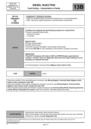
DF119
PRESENT
OR
STOREDCAMSHAFT SENSOR SIGNAL
1.DEF: No camshaft signal or timing fault (belt tension or timing adjustment)
2.DEF: Feed fault, signal interference, camshaft sensor internal fault.
NOTESConditions for applying the fault finding procedure to a stored fault:
The fault is declared present after:
– starting the engine,
– a road test.
Special notes:
Difficulty starting engine.
No effect while driving.
If the fault is present, the level 1 warning light will illuminate.
Use bornier Elé.1681 for any operations on the injection computer connectors.
IMPORTANT
If fault DF119 appears with status 2.DEF and PR055 Engine speed (stored
context) < 150 rpm, there is a diagnostic fault due to the engine stalling: It is not
necessary to interpret this fault.
Use Wiring Diagram Technical Note, Mégane II ph2, Scénic II ph2.
1.DEF
NOTESNone.
Check the condition of the camshaft sensor connector (see Wiring Diagram Technical Note, Mégane II ph2,
Scénic II ph2, component code 746).
Check the condition of the engine management computer connector (see Wiring Diagram Technical Note,
Mégane II ph2, Scénic II ph2, component code 120).
If the connector(s) is/are faulty and if there is a repair procedure (see Technical Note 6015A, Repairing electrical
wiring, Wiring: Precautions for repair), repair the connector, otherwise replace the wiring.
EDC16C36_V44_DF119/EDC16C36_V4C_DF119/EDC16C36_V48_DF119/EDC16C36_V50_DF119/EDC16C36_V54_DF119/
EDC16C36_V58_DF119
AFTER REPAIRDeal with any other faults. Clear the fault memory.
Switch off the ignition until the end of the power-latch phase, and carry out a road test
followed by a check using the diagnostic tool.
EDC16 C36
Program No.: 91
Vdiag No.: 44, 4C, 48,
50, 54, 58
Page 118 of 431

13B-118V9 MR-372-J84-13B450$102.mif
DIESEL INJECTION
Fault finding – Interpretation of faults13B
DF119
CONTINUED 1
WARNING
If the fault is stored:
Visually check the condition of the surrounding area.
If, on detection of the fault, the engine speed is considerably slower than the idling speed (less than 400 rpm) and
no customer complaint is declared (warning light indicated by the customer does not come on and vehicle can be
started), the fault was detected because the engine stalled. Clear the fault and carry out a road test.
Check the sensor mounting and the conformity of the camshaft target.
Check that the camshaft sensor/camshaft sprocket air gap is 3 mm maximum.
Check the electrical specifications of the sensor:
Note:
Make sure that the resistance is measured between the tracks indicated.
1. Disconnect the sensor before measuring the resistance with an Ohmmeter or multimeter.
2. The resistance between connections 3FB and 3PL of component 746 (earth and supply) must be between
7.2 kΩ and 13.4 kΩ (10.2 kΩ nominal).
3. The resistance between connections3FB and 3CQ of component 746 (output and feed) should be above
100 kΩ.
4. The resistance between connections3PL and 3CQ of component 746 (output and earth) should be above
100 kΩ.
If the values are incorrect, replace the camshaft sensor.
Check the continuity of the following connections:
– Connection code 3PL between components 746 and 120.
– Connection code 3CQ between components 746 and 120.
Check for + 12 V after relay on connection 3FB of component 746.
If the connector or connectors are faulty and if there is a repair procedure (see Technical Note 6015A, Repairing
electrical wiring, Wiring: Precautions for repair), repair the connector, otherwise replace the wiring.
If the fault is still present, replace the camshaft sensor.
AFTER REPAIRDeal with any other faults. Clear the fault memory.
Switch off the ignition until the end of the power-latch phase, and carry out a road test
followed by a check using the diagnostic tool.
EDC16 C36
Program No.: 91
Vdiag No.: 44, 4C, 48,
50, 54, 58
Page 119 of 431

13B-119V9 MR-372-J84-13B450$102.mif
DIESEL INJECTION
Fault finding – Interpretation of faults13B
DF119
CONTINUED 2
2.DEFNOTESPriorities when dealing with a number of faults:
Deal with fault DF120 Engine speed sensor signal, 1.DEF
first if it is present or stored.
Check the condition of the camshaft sensor connector (see Wiring Diagram Technical Note, Mégane II ph2,
Scénic II ph2, component code 746).
Check the condition of the engine management computer connector (see Wiring Diagram Technical Note,
Mégane II ph2, Scénic II ph2, component code 120).
If the connector or connectors are faulty and if there is a repair procedure (see Technical Note 6015A, Repairing
electrical wiring, Wiring: Precautions for repair), repair the connector, otherwise replace the wiring.
Check the sensor mounting and the conformity of the camshaft target.
Check that the camshaft sensor/camshaft sprocket air gap is 3 mm maximum.
Check the continuity of the following connections:
– Connection code 3PL between components 746 and 120.
– Connection code 3CQ between components 746 and 120.
Check for + 12 V after relay on connection 3FB of component 746.
If the connector(s) is/are faulty and if there is a repair procedure (see Technical Note 6015A, Repairing electrical
wiring, Wiring: Precautions for repair), repair the connector, otherwise replace the wiring.
– Check the tension of the timing belt.
– Check the conformity of the camshaft sprocket/camshaft assembly.
– Check the timing adjustment.
Carry out the necessary repairs.
If the fault is still present, contact the Techline.
AFTER REPAIRDeal with any other faults. Clear the fault memory.
Switch off the ignition until the end of the power-latch phase, and carry out a road test
followed by a check using the diagnostic tool.
EDC16 C36
Program No.: 91
Vdiag No.: 44, 4C, 48,
50, 54, 58
Page 120 of 431

13B-120V9 MR-372-J84-13B450$102.mif
DIESEL INJECTION
Fault finding – Interpretation of faults13B
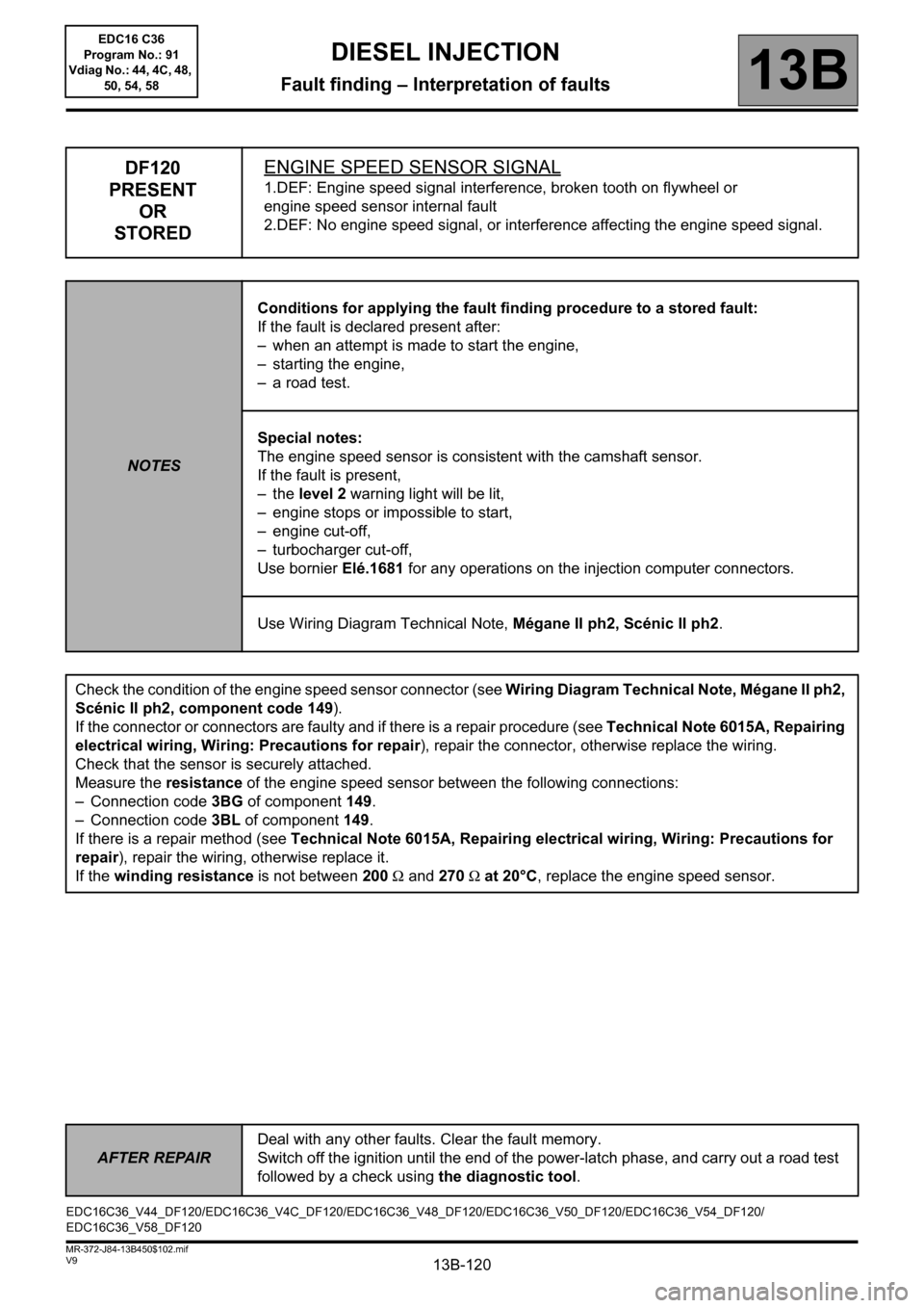
DF120
PRESENT
OR
STOREDENGINE SPEED SENSOR SIGNAL
1.DEF: Engine speed signal interference, broken tooth on flywheel or
engine speed sensor internal fault
2.DEF: No engine speed signal, or interference affecting the engine speed signal.
NOTESConditions for applying the fault finding procedure to a stored fault:
If the fault is declared present after:
– when an attempt is made to start the engine,
– starting the engine,
– a road test.
Special notes:
The engine speed sensor is consistent with the camshaft sensor.
If the fault is present,
–the level 2 warning light will be lit,
– engine stops or impossible to start,
– engine cut-off,
– turbocharger cut-off,
Use bornier Elé.1681 for any operations on the injection computer connectors.
Use Wiring Diagram Technical Note, Mégane II ph2, Scénic II ph2.
Check the condition of the engine speed sensor connector (see Wiring Diagram Technical Note, Mégane II ph2,
Scénic II ph2, component code 149).
If the connector or connectors are faulty and if there is a repair procedure (see Technical Note 6015A, Repairing
electrical wiring, Wiring: Precautions for repair), repair the connector, otherwise replace the wiring.
Check that the sensor is securely attached.
Measure the resistance of the engine speed sensor between the following connections:
– Connection code 3BG of component 149.
– Connection code 3BL of component 149.
If there is a repair method (see Technical Note 6015A, Repairing electrical wiring, Wiring: Precautions for
repair), repair the wiring, otherwise replace it.
If the winding resistance is not between 200 Ω and 270 Ω at 20°C, replace the engine speed sensor.
EDC16C36_V44_DF120/EDC16C36_V4C_DF120/EDC16C36_V48_DF120/EDC16C36_V50_DF120/EDC16C36_V54_DF120/
EDC16C36_V58_DF120
AFTER REPAIRDeal with any other faults. Clear the fault memory.
Switch off the ignition until the end of the power-latch phase, and carry out a road test
followed by a check using the diagnostic tool.
EDC16 C36
Program No.: 91
Vdiag No.: 44, 4C, 48,
50, 54, 58