Page 25 of 431

13B-25V9 MR-372-J84-13B450$050.mif
DIESEL INJECTION
Fault finding – Features13B
EDC16 C36
Program No.: 91
Vdiag No.: 44, 4C, 48,
50, 54, 58
– DF056 Air flowmeter circuit.
– DF107 Computer memory.
– DF200 Atmospheric pressure sensor.
– DF209 EGR valve position sensor circuit.
– DF272 EGR valve control circuit.
– DF310 Particle filter upstream temp.* sensor
– DF315 Particle filter diff.* pressure sensor
– DF316 Particle filter diff* pressure
– DF647 EGR valve position regulation.
Some repair operations require programming to ensure that certain engine components function correctly.
Follow the programming procedures (see Replacement of components), if replacing the exhaust gas
recirculation valve or an injector.
*temp: temperature
* diff: differential
3. Conditions for deleting an OBD fault
An OBD fault is deleted in several phases.
The fault present on the diagnostic tool will only become stored (after a repair operation) after the vehicle has
been driven 3 times.
The OBD warning light will only go out after these 3 trips.
The instrument panel warning light coming on does not automatically mean that the system has a fault.
In order for the OBD fault and display parameters to be cleared from the computer, the system requires
40 engine heating cycles.
An engine heating cycle is a driving cycle during which:
– the engine coolant temperature reaches at least 71.1°C,
– the engine coolant temperature varies by 22.2°C in relation to the engine starting temperature.
If one of these conditions is not fulfilled, the OBD fault will still be present or stored on the injection
computer.
Page 26 of 431

13B-26V9 MR-372-J84-13B450$060.mif
13B
EDC16 C36
Program No.: 91
Vdiag No.: 44, 4C, 48,
50, 54, 58
No.
Defect
modesCause of fault Customer perception
Engine stop– Flow regulator short circuit to earth (flow regulator closed).
– High pressure circuit leak (min. rail pressure).
– Injector jammed open.
– Loss of engine speed signal.
– Sensor feed No.No. 3 fault.
– Engine management computer internal fault.
– Injector row 1 and 2 fault.
– Solenoid control stage cut-off fault caused by computer
initialisation (to check that cut-off is operational).Engine stop
Level 2 on
Limited torque– Rail pressure sensor fault.
– Pedal sensor gangs 1 and 2 double fault (including sensor feeds
1 and 2).
– Open circuit, short circuit to earth and turbocharger solenoid valve
short circuit to + 12 V.
– Turbocharger pressure sensor fault (sensor signal short circuit
with sensor feed, sensor signal short circuit to +12volts, sensor
open circuit to earth, sensor signal short circuit to earth, sensor
feed open circuit, sensor signal open circuit, significant line
resistance on sensor feed, significant line resistance on sensor
signal, significant line resistance on sensor earth, significant
pressure difference measured between the atmospheric pressure
sensor and the turbocharger pressure sensor at idle speed).
– Injector codes fault.
– Computer internal fault.
– Solenoid control stage cut-off fault caused by computer
initialisation (to check that cut-off is operational).
– Sensor feed 1, 2 and 3 fault.
– Vehicle speed fault.Speed limited
to≈1750 rpm
Loss of engine torque
Flow/injected
quantity
limited– Flow regulator open circuit or short circuit to + 12 volts
(Flow regulator open).
– Positive rail pressure loop difference (measurement < setpoint).
– Negative rail pressure loop difference (measurement > setpoint).
– Max. rail pressure (flow regulator jammed in open position).Limited performance
Pedal limp
home– Pedal sensor gangs 1 and 2 double fault (including sensor feeds
1 and 2).
– Activation of pedal safety programming.
– Accelerator pedal mechanism jammed.Speed limited to
45-48 mph (75-80 km/h)
DIESEL INJECTION
Fault finding – Defect modes
Page 27 of 431

13B-27V9 MR-372-J84-13B450$060.mif
DIESEL INJECTION
Fault finding – Defect modes13B
EDC16 C36
Program No.: 91
Vdiag No.: 44, 4C, 48,
50, 54, 58
* normally aspirated: naturally aspiratedDefect
modesCause of fault Customer perception
Turbocharger
cut-off– Turbocharging pressure loop difference (vanes jammed,
compressor/turbine fault, turbocharging pressure sensor fault,
sensor connection fault, functional solenoid valve fault
(disconnected, hose kinked, solenoid valve mechanism jammed),
high pressure circuit leak (high pressure hose, major distributor
leak).
– Flowmeter failure (plausibility of the reading):
– significant line resistance on earth sensor,
– significant line resistance on sensor feed, significant line resistance
on sensor signal,
– flowmeter sensing element damaged,
– wiring/connection fault,
– flowmeter voltage or 5 V reference voltage deviation.
– Flowmeter failure (plausibility of sensitivity variation):
– flowmeter clogged/flow underestimated,
– flow overestimated,
– air circuit leak between flowmeter and compressor,
– air circuit leak after compressor.
– Electrical faults:
– signal short circuit to + 12 V,
– signal short circuit to earth,
– signal open circuit,
– sensor feed open circuit,
– open circuit, short circuit to earth and turbocharger solenoid valve
short circuit to + 12 V.
– Turbocharger pressure sensor fault (sensor signal short circuit with
sensor feed, sensor signal short circuit to + 12 V, sensor open
circuit to earth, sensor signal short circuit to earth, sensor feed open
circuit, sensor signal open circuit, significant line resistance on
sensor feed, significant line resistance on sensor signal, significant
line resistance on sensor earth, significant pressure difference
measured between the atmospheric pressure sensor and the
turbocharger pressure sensor at idle speed).
– EGR valve fault (valve clogged, valve jammed open).
– Camshaft sensor fault.
– Engine speed sensor fault.
– Sensor feed No. 1 fault.25-50% loss of engine
performance (normally
aspirated engine)
Rail pressure
limited– Rail pressure sensor fault.
– Sensor feed No. 3 fault.Poor performance
Rail pressure
reduction
– Positive rail pressure loop difference (measurement < setpoint).
Poor performance
Page 28 of 431
13B-28V9 MR-372-J84-13B450$070.mif
13B
EDC16 C36
Program No.: 91
Vdiag No.: 44, 4C, 48,
50, 54, 58
Summary of available configuration readings
NOTESConfiguration readings are used to check the state of configurations performed.
The configuration readings cannot be changed.
The computer is configured as soon as the one of the vehicle's optional system
components is operated.
In the event of a fault, consult the interpretation of command RZ005 Programming.
LC009Air conditioning
WITH OR WITHOUT
LC056Heating elements
WITH OR WITHOUT
LC065Water in diesel fuel sensor
WITH OR WITHOUT
LC120Cruise control
WITH OR WITHOUT
LC121Speed limiter
WITH OR WITHOUT
DIESEL INJECTION
Fault finding – Configuration and programming
Page 29 of 431

13B-29V9 MR-372-J84-13B450$080.mif
13B
EDC16 C36
Program No.: 91
Vdiag No.: 44, 4C, 48,
50, 54, 58
COMPUTER REPLACEMENT OR REPROGRAMMING
Two operations must be performed when replacing or reprogramming the computer:
SC003 Save computer data and SC001 Enter saved data.
–Run SC003 Save computer data before replacing or reprogramming the computer. This enables certain data
to be saved in the diagnostic tool so that the new computer* can be reconfigured like the old one. The saved data
are: injector codes, EGR programming, vehicle options.
–Run SC001 Enter saved data after replacing or reprogramming the computer. This enables the data (saved by
the command SC003 Save computer data) to be rewritten in the new computer*.
If you cannot establish dialogue with the computer being replaced: you will not be able to save anything.
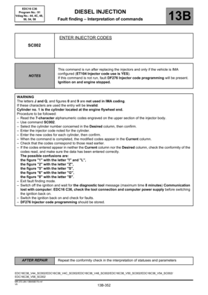
After replacing the computer, write the IMA codes of each injector manually using command SC002 Enter injector
codes by reading the code on each injector (see Replacing the injectors).
Only on F9Q816 engines:
– Enter the data specific to particle filter operation by running SC036 Reinitialise programming and selecting after
replacing injection computer with no save option.
Exhaust gas recirculation valve data is programmed automatically the 1st time the new computer is turned on*.
* New computer or reprogrammed computer.
Specific to the cruise control/speed limiter operation to be carried out before reprogramming of the computer:
Before reprogramming the injection computer, move the main Cruise control/Speed limiter switch to the rest
position. The information about the cruise control or the speed limiter displayed on the instrument panel
disappears.
Otherwise, if the main switch remains in the cruise control or speed limiter position during and after reprogramming,
the Cruise control/Speed limiter function will not be operational.
The procedure for resetting the function is as follows:
– Vehicle ignition on.
– Position the main switch in rest position (the computer then detects the rest position).
– Position the switch in Cruise control position to activate the Cruise control function.
– Position the switch in Speed limiter position to activate the Speed limiter function. IMPORTANT
– Switch on the diagnostic tool (mains or cigarette lighter supply).
– Connect a battery charger.
– Cut off all the electrical consumers (lights, interior lighting, air conditioning, radio CD, etc.).
– Wait for the engine to cool (engine coolant temperature < 60° and air temperature < 50°).
– During (re)programming, the instrument panel screen displays "Oil pressure fault".
Ignore this message and do not take any action in connection with it.
DIESEL INJECTION
Fault finding – Replacement of components
Page 30 of 431

13B-30V9 MR-372-J84-13B450$080.mif
DIESEL INJECTION
Fault finding – Replacement of components13B
EDC16 C36
Program No.: 91
Vdiag No.: 44, 4C, 48,
50, 54, 58
PROCEDURE:
Before replacing or reprogramming the computer:
–Select SC003 Save computer data,
– if the following message appears: a saved file exists; do you want to overwrite this data?: (this file corresponds
to the last save carried out on the tool)
–select "YES".
When the save has been performed, replace the computer or carry out the programming then proceed to the next
step.
After replacing or reprogramming the computer:
–Select SC001 Enter saved data, then follow the instructions given by the diagnostic tool,
– if the VIN is not entered (see Computer identification on the main screen),
–select VP010 Enter VIN,
When both these commands have finished:
– Switch off the ignition and wait for the diagnostic tool message (maximum time 8 minutes) Communication lost
with computer: EDC16 C36, check the tool connection and computer power supply before switching the
ignition back on.
(The powerlatch duration depends on the coolant temperature and activation time of the turbocharger
coolant pump. This operation finishes when the pump is deactivated.)
– then check the system faults, and clear any stored faults,
– if there are faults, deal with the present faults,
– clear the faults from the computer memory.
Carry out a road test followed by another check with the diagnostic tool.
End of the procedure.IMPORTANT
– The injection computer retains the immobiliser code for life.
– The system has no security code.
– It is forbidden to perform tests with computers borrowed from the Parts Department or from another vehicle
which must then be returned.
– These computers are hard-coded.
– If the injection computer appears to be faulty, contact the Techline and refer to the fault finding log.
Page 31 of 431

13B-31V9 MR-372-J84-13B450$080.mif
DIESEL INJECTION
Fault finding – Replacement of components13B
EDC16 C36
Program No.: 91
Vdiag No.: 44, 4C, 48,
50, 54, 58
REPLACING THE INJECTORS
After one or more injectors have been replaced, enter the IMA codes again and then run command SC036
Reinitialise programming.
The system must be configured via the diagnostic socket using the RENAULT CLIP diagnostic tool.
PROCEDURE to be followed after replacing one or more injectors:
– Note the "IMA" code(s) engraved on the injector bodies,
– enter these codes in the computer using command SC002 Enter injector codes, then follow the instructions given
by the diagnostic tool,
– once the command has finished,
–switch off the ignition and wait for the diagnostic tool message (maximum time 8 minutes) Communication
lost with computer: EDC16 C36, check the tool connection and computer power supply before switching the
ignition back on.
– Return to fault finding mode.
– select the Identify computer function from the main screen.
– check that the injector codes entered into the computer match those found on the bodies of the injectors:
– If the codes do not match, restart the command SC002 Enter injector codes procedure.
– If the codes correspond, run command SC036 Reinitialise programming,
–select Injectors as the type of operation, then follow the instructions given by the diagnostic tool.
– Then check the system faults, and clear any stored faults.
– if there are faults, deal with the present faults,
– clear the faults from the computer memory.
Carry out a road test followed by another check with the diagnostic tool.
End of the procedure.Note:
The IMA coding (individual injector correction) is a calibration made in production on each injector to adjust
the flow accurately.
These correction values are etched onto the Bakelite body of each injector (7 alphanumeric characters) and then
entered into the computer which then controls each injector taking into account its individual manufacturing
variation.
IMPORTANT
Cylinder no. 1 is located on the engine flywheel end.
IMPORTANT
Engines can only operate correctly if the correct IMA codes have been entered.
If no code has been entered, or if an implausible code has been entered, fault DF276 "Injector Code
Programming" will be present, and the engine will be in defect mode (engine speed is reduced
significantly).
If another injector's code has been entered, the system will accept it but will make the wrong correction.
This could lead to engine damage, loss of performance and excessive pollution.
Always use the correct injector codes for the engine cylinder/computer.
Page 32 of 431

13B-32V9 MR-372-J84-13B450$080.mif
DIESEL INJECTION
Fault finding – Replacement of components13B
EDC16 C36
Program No.: 91
Vdiag No.: 44, 4C, 48,
50, 54, 58
REPLACING THE EXHAUST GAS RECIRCULATION VALVE (EGR valve)
After the exhaust gas recirculation valve has been replaced, the computer must store the new valve's offset and the
offset measured the last time the ignition was switched off, which is when the valve closed.
Using this data, the computer can detect whether the valve is clogged or seized.
When the valve is replaced, clear the stored offsets so that the program uses the new valve’s offset value.
The data linked to this strategy is compiled in the Emission control/OBD sub-function.
– PR128: First EGR valve offset.
–PR129: Last EGR valve offset > or = PR128 if the valve is new.
The PR128 and PR129 programming must be cleared every time the exhaust gas recirculation valve is replaced.
PROCEDURE to be followed after replacing the exhaust gas recirculation valve:
– Run command SC036 Reinitialise programming,
–select EGR valve as the type of operation, then follow the instructions given by the diagnostic tool,
– When the command is finished,
– switch off the ignition and wait for the diagnostic tool message (maximum time 8 minutes) Communication lost
with computer: EDC16 C36, check the tool connection and computer power supply before switching the ignition
back on.
When the ignition is next switched on again the new EGR valve offset is automatically reprogrammed.
– Start the vehicle to enable the latest EGR valve offset to be programmed,
– Switch off the ignition and wait for the diagnostic tool message (maximum time 8 minutes) Communication lost
with computer: EDC16 C36, check the tool connection and computer power supply before switching the
ignition back on.
The last EGR valve offset reprogrammed is stored on the computer.
– Then check the system faults, and clear any stored faults.
– if there are faults, deal with the present faults,
– clear the faults from the computer memory.
Carry out a road test followed by another check with the diagnostic tool.
End of the procedure.Note:
When the reinitialisation is complete, the Emission control/OBD sub-function displays:
PR128 = PR129 > 100 %
Note:
When the new EGR valve offset is reprogrammed, the Emission control/OBD sub-function displays:
10 % < PR128 < 40 %
PR129 > 100 %
Note:
When the reprogramming of the last EGR valve offset is complete, the Emission control/OBD sub-function
displays:
10 % < PR128 < 40 %
10% < PR129 < 40% and -1%
≤ PR129 – PR128 ≤ 5%