2011 INFINITI QX56 turn signal
[x] Cancel search: turn signalPage 4143 of 5598

PWC-58
< DTC/CIRCUIT DIAGNOSIS >
POWER WINDOW SERIAL LINK
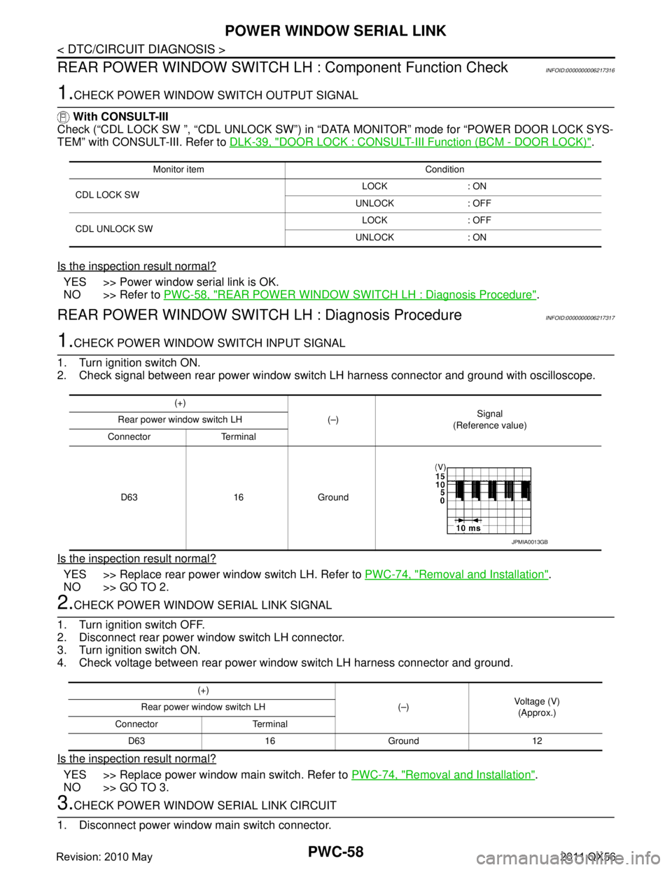
REAR POWER WINDOW SWITCH LH : Component Function Check
INFOID:0000000006217316
1.CHECK POWER WINDOW SWITCH OUTPUT SIGNAL
With CONSULT-III
Check (“CDL LOCK SW ”, “CDL UNLOCK SW”) in “D ATA MONITOR” mode for “POWER DOOR LOCK SYS-
TEM” with CONSULT-III. Refer to DLK-39, "
DOOR LOCK : CONSULT-III Function (BCM - DOOR LOCK)".
Is the inspection result normal?
YES >> Power window serial link is OK.
NO >> Refer to PWC-58, "
REAR POWER WINDOW SWITCH LH : Diagnosis Procedure".
REAR POWER WINDOW SWIT CH LH : Diagnosis ProcedureINFOID:0000000006217317
1.CHECK POWER WINDOW SWITCH INPUT SIGNAL
1. Turn ignition switch ON.
2. Check signal between rear power window switch LH harness connector and ground with oscilloscope.
Is the inspection result normal?
YES >> Replace rear power window switch LH. Refer to PWC-74, "Removal and Installation".
NO >> GO TO 2.
2.CHECK POWER WINDOW SERIAL LINK SIGNAL
1. Turn ignition switch OFF.
2. Disconnect rear power window switch LH connector.
3. Turn ignition switch ON.
4. Check voltage between rear power window switch LH harness connector and ground.
Is the inspection result normal?
YES >> Replace power window main switch. Refer to PWC-74, "Removal and Installation".
NO >> GO TO 3.
3.CHECK POWER WINDOW SERIAL LINK CIRCUIT
1. Disconnect power window main switch connector.
Monitor item Condition
CDL LOCK SW LOCK : ON
UNLOCK : OFF
CDL UNLOCK SW LOCK : OFF
UNLOCK : ON
(+) (–)Signal
(Reference value)
Rear power window switch LH
Connector Terminal
D63 16 Ground
JPMIA0013GB
(+) (–)Voltage (V)
(Approx.)
Rear power window switch LH
Connector Terminal D63 16Ground12
Revision: 2010 May2011 QX56
Page 4144 of 5598

POWER WINDOW SERIAL LINKPWC-59
< DTC/CIRCUIT DIAGNOSIS >
C
DE
F
G H
I
J
L
M A
B
PWC
N
O P
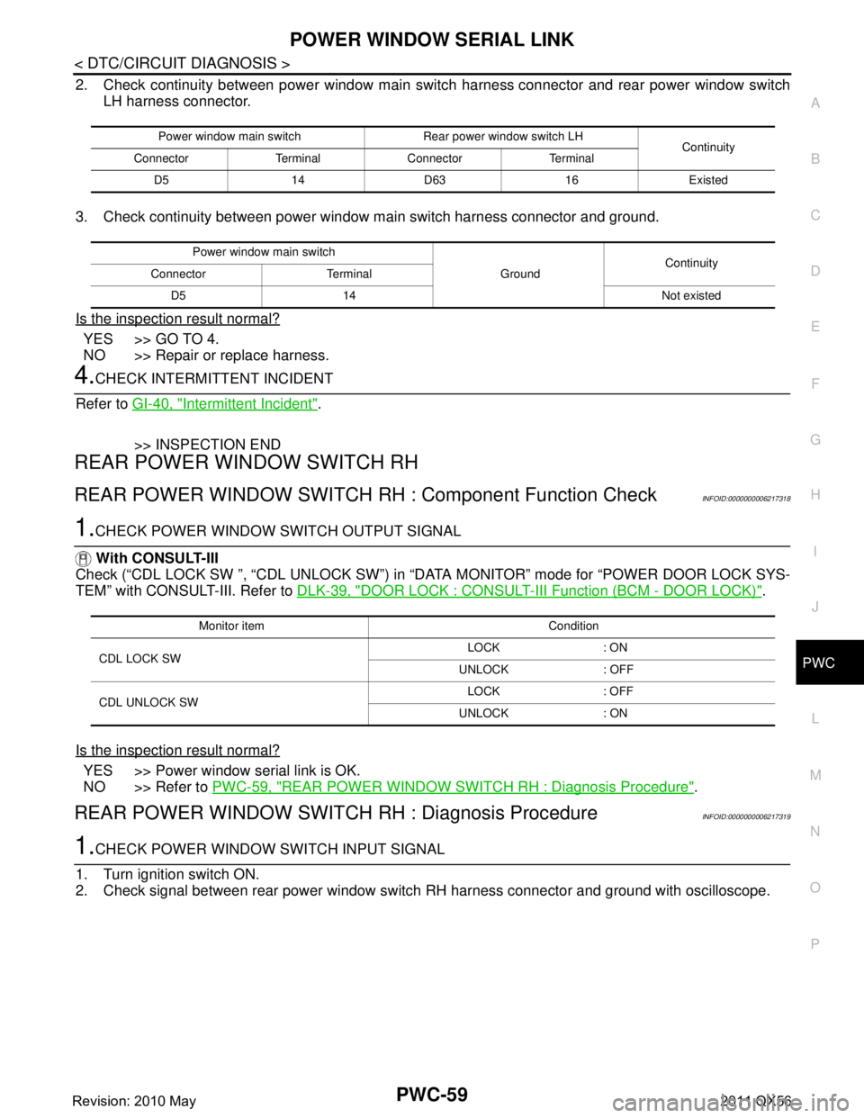
2. Check continuity between power window main s witch harness connector and rear power window switch
LH harness connector.
3. Check continuity between power window main switch harness connector and ground.
Is the inspection result normal?
YES >> GO TO 4.
NO >> Repair or replace harness.
4.CHECK INTERMITTENT INCIDENT
Refer to GI-40, "
Intermittent Incident".
>> INSPECTION END
REAR POWER WINDOW SWITCH RH
REAR POWER WINDOW SWITCH RH : Component Function CheckINFOID:0000000006217318
1.CHECK POWER WINDOW SWITCH OUTPUT SIGNAL
With CONSULT-III
Check (“CDL LOCK SW ”, “CDL UNLOCK SW”) in “D ATA MONITOR” mode for “POWER DOOR LOCK SYS-
TEM” with CONSULT-III. Refer to DLK-39, "
DOOR LOCK : CONSULT-III Function (BCM - DOOR LOCK)".
Is the inspection result normal?
YES >> Power window serial link is OK.
NO >> Refer to PWC-59, "
REAR POWER WINDOW SWITCH RH : Diagnosis Procedure".
REAR POWER WINDOW SWITCH RH : Diagnosis ProcedureINFOID:0000000006217319
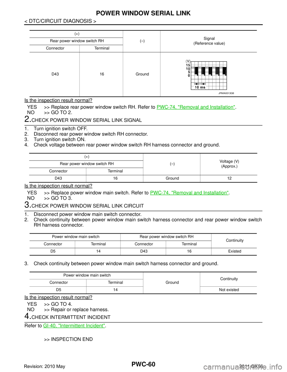
1.CHECK POWER WINDOW SWITCH INPUT SIGNAL
1. Turn ignition switch ON.
2. Check signal between rear power window swit ch RH harness connector and ground with oscilloscope.
Power window main switch Rear power window switch LH
Continuity
Connector Terminal Connector Terminal
D5 14 D63 16 Existed
Power window main switch GroundContinuity
Connector Terminal
D5 14 Not existed
Monitor item Condition
CDL LOCK SW LOCK : ON
UNLOCK : OFF
CDL UNLOCK SW LOCK : OFF
UNLOCK : ON
Revision: 2010 May2011 QX56
Page 4145 of 5598

PWC-60
< DTC/CIRCUIT DIAGNOSIS >
POWER WINDOW SERIAL LINK
Is the inspection result normal?
YES >> Replace rear power window switch RH. Refer to PWC-74, "Removal and Installation".
NO >> GO TO 2.
2.CHECK POWER WINDOW SERIAL LINK SIGNAL
1. Turn ignition switch OFF.
2. Disconnect rear power window switch RH connector.
3. Turn ignition switch ON.
4. Check voltage between rear power window switch RH harness connector and ground.
Is the inspection result normal?
YES >> Replace power window main switch. Refer to PWC-74, "Removal and Installation".
NO >> GO TO 3.
3.CHECK POWER WINDOW SERIAL LINK CIRCUIT
1. Disconnect power window main switch connector.
2. Check continuity between power window main s witch harness connector and rear power window switch
RH harness connector.
3. Check continuity between power window main switch harness connector and ground.
Is the inspection result normal?
YES >> GO TO 4.
NO >> Repair or replace harness.
4.CHECK INTERMITTENT INCIDENT
Refer to GI-40, "
Intermittent Incident".
>> INSPECTION END
(+) (–)Signal
(Reference value)
Rear power window switch RH
Connector Terminal
D43 16 Ground
JPMIA0013GB
(+) (–)Voltage (V)
(Approx.)
Rear power window switch RH
Connector Terminal D43 16Ground12
Power window main switch Re ar power window switch RH
Continuity
Connector Terminal Connector Terminal
D5 14 D43 16 Existed
Power window main switch GroundContinuity
Connector Terminal
D5 14 Not existed
Revision: 2010 May2011 QX56
Page 4161 of 5598

PWO-2
Diagnosis Procedure ..............................................23
AC 120 V OUTLET MAIN SWITCH POWER
SUPPLY CIRCUIT .......................................... ...
24
Diagnosis Procedure ........................................... ...24
AC 120 V OUTLET MAIN SWITCH INPUT
SIGNAL CIRCUIT ..............................................
25
Diagnosis Procedure ........................................... ...25
Component Inspection ............................................25
AC 120 V POWER OUTPUT CIRCUIT ..............27
Diagnosis Procedure ........................................... ...27
AC 120 V OUTLET MAIN SWITCH INDICA-
TOR CIRCUIT ................................................. ...
29
Diagnosis Procedure ........................................... ...29
SYMPTOM DIAGNOSIS .............................31
NO OUTPUT FROM AC 120 V OUTLET ........ ...31
Diagnosis Procedure ........................................... ...31
AC 120 V OUTLET MAIN SWITCH INDICA-
TOR DOES NOT TURN ON ..............................
32
Diagnosis Procedure ............................................ ...32
NORMAL OPERATING CONDITION ................33
Description ........................................................... ...33
REMOVAL AND INSTALLATION ..............34
INVERTER UNIT ............................................. ...34
Removal and Installation ...................................... ...34
AC 120V OUTLET MAIN SW ............................35
Removal and Installation ...................................... ...35
AC 120 V OUTLET ............................................36
Removal and Installation ...................................... ...36
SERVICE DATA AND SPECIFICATIONS
(SDS) .......... ................................................
37
SERVICE DATA AND SPECIFICATIONS
(SDS) .............................................................. ...
37
AC 120 V Power Outlet ........................................ ...37
Revision: 2010 May2011 QX56
Page 4174 of 5598
![INFINITI QX56 2011 Factory Service Manual
PWO
SYSTEMPWO-15
< SYSTEM DESCRIPTION > [AC 120 V OUTLET]
C
D
E
F
G H
I
J
K L
B A
O P
N
SYSTEM
System DescriptionINFOID:0000000006257071
SYSTEM DIAGRAM
SYSTEM DESCRIPTION
When turning ON the AC 120 INFINITI QX56 2011 Factory Service Manual
PWO
SYSTEMPWO-15
< SYSTEM DESCRIPTION > [AC 120 V OUTLET]
C
D
E
F
G H
I
J
K L
B A
O P
N
SYSTEM
System DescriptionINFOID:0000000006257071
SYSTEM DIAGRAM
SYSTEM DESCRIPTION
When turning ON the AC 120](/manual-img/42/57033/w960_57033-4173.png)
PWO
SYSTEMPWO-15
< SYSTEM DESCRIPTION > [AC 120 V OUTLET]
C
D
E
F
G H
I
J
K L
B A
O P
N
SYSTEM
System DescriptionINFOID:0000000006257071
SYSTEM DIAGRAM
SYSTEM DESCRIPTION
When turning ON the AC 120 V outlet main switch with the ignition switch ON, the indicator turns ON and the
inverter unit is activated.
The inverter unit converts power supply voltage to AC 120 V and outputs the converted voltage to the AC
120 V outlet two seconds after the AC 120 V outlet main switch is turned ON.
Fail-safeINFOID:0000000006257269
When a malfunction listed below occurs, the inverter unit turns OFF the AC 120 V outlet main switch indicator
and stops the output by operating the fail-safe.
JSMIA0295GB
Malfunction item Fail-safe condition Fail-safe cancellation condition
Inverter unit is overheat-
ed When the inverter unit is overheated, the output
stops to protect the inverter unit. After the inverter unit temperature is lowered, the
AC 120 V outlet main switch ON
⇒ OFF ⇒ ON op-
eration allows normal return.
Inverter unit power sup-
ply voltage is 11.5 V or
less When inverter unit input voltage is lowered, the out-
put stops to protect the battery from running out.
Automatic normal return wh
en inverter unit power
supply voltage reaches 11.5 V - 16 V.
Inverter unit power sup-
ply voltage is 16 V - 18 V When inverter unit input voltage reaches 16 V - 18 V,
the output stops to protect the inverter unit. Automatic normal return wh
en inverter unit power
supply voltage reaches 11.5 V - 16 V.
Inverter unit power sup-
ply voltage is 18 V or
more When inverter unit input voltage reaches 18 V or
more, the output stops to protect the inverter unit. After the inverter unit power supply voltage reaches
11.5 V - 16 V, the AC 120 V outlet main switch ON
⇒
OFF ⇒ ON operation allows normal return.
Inverter unit output cur-
rent is 2.8 A or more When inverter unit output current reaches 2.8 A or
more, the output stops to prevent over current. (e.g.
connecting an electric appliance exceeding rated
output)
Automatic normal return wh
en inverter output cur-
rent reaches 2.8 A.
Inverter unit output signal
(AC 120 V output signal)
is shorted When inverter unit output signal is shorted, the out-
put stops. After recovering from inverter unit output signal
short, the AC 120 V outlet main switch ON
⇒ OFF
⇒ ON operation allows normal return.
Revision: 2010 May2011 QX56
Page 4176 of 5598
![INFINITI QX56 2011 Factory Service Manual
PWO
INVERTER UNITPWO-17
< ECU DIAGNOSIS INFORMATION > [AC 120 V OUTLET]
C
D
E
F
G H
I
J
K L
B A
O P
N
CAUTION:
To measure AC 120 V output signal, always use th
e circuit tester or oscilloscope AC r INFINITI QX56 2011 Factory Service Manual
PWO
INVERTER UNITPWO-17
< ECU DIAGNOSIS INFORMATION > [AC 120 V OUTLET]
C
D
E
F
G H
I
J
K L
B A
O P
N
CAUTION:
To measure AC 120 V output signal, always use th
e circuit tester or oscilloscope AC r](/manual-img/42/57033/w960_57033-4175.png)
PWO
INVERTER UNITPWO-17
< ECU DIAGNOSIS INFORMATION > [AC 120 V OUTLET]
C
D
E
F
G H
I
J
K L
B A
O P
N
CAUTION:
To measure AC 120 V output signal, always use th
e circuit tester or oscilloscope AC range.
Never allow the probes to contact each other.
Because of modified sine wave output of the AC 120 V output signal, voltage cannot be measured
accurately without using a circuit tester that can measure true RMS (root mean square).
Fail-safeINFOID:0000000006257075
When a malfunction listed below occurs, the inverter unit turns OFF the AC 120 V outlet main switch indicator
and stops the output by operating the fail-safe.
6
(W)
Ground AC 120 V outlet main
switch
InputIgnition
switch ON When AC 120 V outlet
main switch OFF
0 V
When AC 120 V outlet
main switch ON 12 V
7
(O) AC 120 V outlet main
switch indicator
OutputIgnition
switch ON When AC 120 V outlet
main switch OFF
0 V
When AC 120 V outlet
main switch ON 5.2 V
8
(G/Y) Ground — Ignition switch ON 0 V
Te r m i n a l N o .
(Wire color) Description
Condition Va l u e
(Approx.)
+ − Signal name Input/
Output
Malfunction item Fail-safe condition Fail-safe cancellation condition
Inverter unit is overheat-
ed When the inverter unit is overheated, the output
stops to protect the inverter unit. After the inverter unit temperature is lowered, the
AC 120 V outlet main switch ON
⇒ OFF ⇒ ON op-
eration allows normal return.
Inverter unit power sup-
ply voltage is 11.5 V or
less When inverter unit input voltage is lowered, the out-
put stops to protect the battery from running out.
Automatic normal return wh
en inverter unit power
supply voltage reaches 11.5 V - 16 V.
Inverter unit power sup-
ply voltage is 16 V - 18 V When inverter unit input voltage reaches 16 V - 18 V,
the output stops to protect the inverter unit. Automatic normal return wh
en inverter unit power
supply voltage reaches 11.5 V - 16 V.
Inverter unit power sup-
ply voltage is 18 V or
more When inverter unit input voltage reaches 18 V or
more, the output stops to protect the inverter unit. After the inverter unit power supply voltage reaches
11.5 V - 16 V, the AC 120 V outlet main switch ON
⇒
OFF ⇒ ON operation allows normal return.
Inverter unit output cur-
rent is 2.8 A or more When inverter unit output current reaches 2.8 A or
more, the output stops to prevent over current. (e.g.
connecting an electric appliance exceeding rated
output) Automatic normal return wh
en inverter output cur-
rent reaches 2.8 A.
Inverter unit output signal
(AC 120 V output signal)
is shorted When inverter unit output signal is shorted, the out-
put stops. After recovering from inverter unit output signal
short, the AC 120 V outlet main switch ON
⇒ OFF
⇒ ON operation allows normal return.
Revision: 2010 May2011 QX56
Page 4182 of 5598
![INFINITI QX56 2011 Factory Service Manual
PWO
POWER SUPPLY AND GROUND CIRCUITPWO-23
< DTC/CIRCUIT DIAGNOSIS > [AC 120 V OUTLET]
C
D
E
F
G H
I
J
K L
B A
O P
N
DTC/CIRCUIT DIAGNOSIS
POWER SUPPLY AND GROUND CIRCUIT
Diagnosis ProcedureINFOID:000 INFINITI QX56 2011 Factory Service Manual
PWO
POWER SUPPLY AND GROUND CIRCUITPWO-23
< DTC/CIRCUIT DIAGNOSIS > [AC 120 V OUTLET]
C
D
E
F
G H
I
J
K L
B A
O P
N
DTC/CIRCUIT DIAGNOSIS
POWER SUPPLY AND GROUND CIRCUIT
Diagnosis ProcedureINFOID:000](/manual-img/42/57033/w960_57033-4181.png)
PWO
POWER SUPPLY AND GROUND CIRCUITPWO-23
< DTC/CIRCUIT DIAGNOSIS > [AC 120 V OUTLET]
C
D
E
F
G H
I
J
K L
B A
O P
N
DTC/CIRCUIT DIAGNOSIS
POWER SUPPLY AND GROUND CIRCUIT
Diagnosis ProcedureINFOID:0000000006257089
1.CHECK FUSE
Check that the following fuse is not blown.
Is the fuse fusing?
YES >> Replace the blown fuse after repairing the affected circuit if a fuse is blown.
NO >> GO TO 2.
2.CHECK INVERTER UNIT POWER SUPPLY CIRCUIT
Check voltage between inverter unit harness connector and ground.
Is the inspection result normal?
YES >> GO TO 3.
NO >> Repair or replace the inverter unit power supply circuit.
3.CHECK INVERTER UNIT GROUND CIRCUIT
1. Turn the ignition switch OFF.
2. Disconnect the inverter unit connector.
3. Check for continuity between inverter unit harness connector and ground.
Is the inspection result normal?
YES >> INSPECTION END
NO >> Repair or replace the inverter unit ground circuit.
Signal name Fuse No.
Battery power supply 79
Te r m i n a l Condition
Vo l ta g e
(Approx.)
(+) (–)
Inverter unit GroundIgnition switch
Connector Terminal
M143 4 OFF Battery voltage
Inverter unit GroundContinuity
Connector Terminal
M143 8 Existed
Revision: 2010 May2011 QX56
Page 4183 of 5598
![INFINITI QX56 2011 Factory Service Manual
PWO-24
< DTC/CIRCUIT DIAGNOSIS >[AC 120 V OUTLET]
AC 120 V OUTLET MAIN SWITCH POWER SUPPLY CIRCUIT
AC 120 V OUTLET MAIN SWITCH
POWER SUPPLY CIRCUIT
Diagnosis ProcedureINFOID:0000000006257095
1.CHECK INFINITI QX56 2011 Factory Service Manual
PWO-24
< DTC/CIRCUIT DIAGNOSIS >[AC 120 V OUTLET]
AC 120 V OUTLET MAIN SWITCH POWER SUPPLY CIRCUIT
AC 120 V OUTLET MAIN SWITCH
POWER SUPPLY CIRCUIT
Diagnosis ProcedureINFOID:0000000006257095
1.CHECK](/manual-img/42/57033/w960_57033-4182.png)
PWO-24
< DTC/CIRCUIT DIAGNOSIS >[AC 120 V OUTLET]
AC 120 V OUTLET MAIN SWITCH POWER SUPPLY CIRCUIT
AC 120 V OUTLET MAIN SWITCH
POWER SUPPLY CIRCUIT
Diagnosis ProcedureINFOID:0000000006257095
1.CHECK FUSE
Check that the following fuse is not blown.
Is the fuse fusing?
YES >> Replace the blown fuse after repairing the affected circuit if a fuse is blown.
NO >> GO TO 2.
2.CHECK POWER SUPPLY FOR AC 120 V OUTLET MAIN SWITCH
1. Turn ignition switch ON.
2. Check for voltage between the AC 120 V main switch harness connector and ground.
Is the inspection result normal?
YES >> INSPECTION END
NO >> Repair the AC 120 V main switch power supply circuit.
Signal name Fuse No.
Ignition power supply 3
Te r m i n a l s Condition
Vo l ta g e
(Approx.)
(+) (–)
AC 120 V outlet main switch
GroundIgnition switch
Connector Terminal
M144 1 OFF 0 V
ON 12 V
Revision: 2010 May2011 QX56