2011 INFINITI QX56 turn signal
[x] Cancel search: turn signalPage 4184 of 5598
![INFINITI QX56 2011 Factory Service Manual
PWO
AC 120 V OUTLET MAIN SWITCH INPUT SIGNAL CIRCUITPWO-25
< DTC/CIRCUIT DIAGNOSIS > [AC 120 V OUTLET]
C
D
E
F
G H
I
J
K L
B A
O P
N
AC 120 V OUTLET MAIN SWITCH
INPUT SIGNAL CIRCUIT
Diagnosis Proced INFINITI QX56 2011 Factory Service Manual
PWO
AC 120 V OUTLET MAIN SWITCH INPUT SIGNAL CIRCUITPWO-25
< DTC/CIRCUIT DIAGNOSIS > [AC 120 V OUTLET]
C
D
E
F
G H
I
J
K L
B A
O P
N
AC 120 V OUTLET MAIN SWITCH
INPUT SIGNAL CIRCUIT
Diagnosis Proced](/manual-img/42/57033/w960_57033-4183.png)
PWO
AC 120 V OUTLET MAIN SWITCH INPUT SIGNAL CIRCUITPWO-25
< DTC/CIRCUIT DIAGNOSIS > [AC 120 V OUTLET]
C
D
E
F
G H
I
J
K L
B A
O P
N
AC 120 V OUTLET MAIN SWITCH
INPUT SIGNAL CIRCUIT
Diagnosis ProcedureINFOID:0000000006257093
1.CHECK HARNESS BETWEEN INVERTER UNIT AND AC 120 V OUTLET MAIN SWITCH
1. Turn ignition switch OFF.
2. Disconnect inverter unit connector and AC 120 V outlet main switch connector.
3. Check for continuity between the inverter unit harness connector and AC 120 V outlet main switch har- ness connector.
4. Check for continuity between inverter unit harness connector and ground.
Is the inspection result normal?
YES >> GO TO 2.
NO >> Repair the harnesses or connectors.
2.CHECK AC 120 V OUTLET MAIN SWITCH INPUT SIGNAL
1. Connect inverter unit connector and AC 120 V outlet main switch connector.
2. Turn ignition switch ON.
3. AC 120 V outlet main switch ON.
4. Check for voltage between the inverter unit harness connector and ground.
Is the inspection result normal?
YES >> INSPECTION END
NO >> GO TO 3.
3.CHECK AC 120 V OUTLET MAIN SWITCH
1. Turn ignition switch OFF.
2. Remove AC 120 V outlet main switch.
3. Check AC 120 V outlet main switch. Refer to PWO-25, "
Component Inspection".
Is the inspection result normal?
YES >> INSPECTION END
NO >> Replace AC 120 V outlet main switch.
Component InspectionINFOID:0000000006257096
1.CHECK AC 120 V OUTLET MAIN SWITCH
Check continuity of AC 120 V outlet main switch.
Inverter unit AC 120 V outlet main switch Continuity
Connector Terminal Connector Terminal
M1436M1443Existed
Inverter unit GroundContinuity
Connector Terminal
M143 6 Not existed
Te r m i n a l s Condition
Vol tag e
(Approx.)
(+) (–)
Inverter unit
GroundAC 120 V out-
let main switch
Connector Terminal
M143 6 OFF 0 V
ON 12 V
Revision: 2010 May2011 QX56
Page 4186 of 5598
![INFINITI QX56 2011 Factory Service Manual
PWO
AC 120 V POWER OUTPUT CIRCUIT
PWO-27
< DTC/CIRCUIT DIAGNOSIS > [AC 120 V OUTLET]
C
D
E
F
G H
I
J
K L
B A
O P
N
AC 120 V POWER OUTPUT CIRCUIT
Diagnosis ProcedureINFOID:0000000006257091
1.CHECK HAR INFINITI QX56 2011 Factory Service Manual
PWO
AC 120 V POWER OUTPUT CIRCUIT
PWO-27
< DTC/CIRCUIT DIAGNOSIS > [AC 120 V OUTLET]
C
D
E
F
G H
I
J
K L
B A
O P
N
AC 120 V POWER OUTPUT CIRCUIT
Diagnosis ProcedureINFOID:0000000006257091
1.CHECK HAR](/manual-img/42/57033/w960_57033-4185.png)
PWO
AC 120 V POWER OUTPUT CIRCUIT
PWO-27
< DTC/CIRCUIT DIAGNOSIS > [AC 120 V OUTLET]
C
D
E
F
G H
I
J
K L
B A
O P
N
AC 120 V POWER OUTPUT CIRCUIT
Diagnosis ProcedureINFOID:0000000006257091
1.CHECK HARNESS BETWEEN INVERTER UNIT AND AC 120 V OUTLET
1. Turn ignition switch OFF.
2. Disconnect inverter unit connector and AC 120 V outlet connector.
3. Check for continuity between the inverter uni t harness connector and AC 120 V outlet harness connector.
4. Check for continuity between inverter unit harness connector and ground.
5. Check for continuity between inverter unit harness connector.
Is the inspection result normal?
YES >> GO TO 2.
NO >> Repair or replace the harnesses or connectors.
2.CHECK INVERTER UNIT OUTPUT SIGNAL
1. Connect inverter unit connector and AC 120 V outlet connector.
2. Turn ignition switch ON.
3. AC 120 V outlet main switch ON. (AC 120 V outlet main switch indicator ON)
4. Check voltage between inverter unit harness connector.
CAUTION:
To measure AC 120 V output signal, al ways use the circuit tester AC range.
Never allow the probes to contact each other.
Is the inspection result normal?
YES >> GO TO 3
NO >> Replace inverter unit.
3.CHECK AC 120 V OUTLET VOLTAGE
1. AC 120 V outlet main switch ON. (AC 120 V outlet main switch indicator ON)
2. Check voltage between AC 120 V outlet.
Inverter unit AC 120 V outlet Continuity
Connector Terminal Connector Terminal
M143 5
M145 1
Existed
12
Inverter unit GroundContinuity
Connector Terminal
M143 5
Not existed
1
Inverter unit Continuity
Connector Terminal
M143 5 1 Not existed
Te r m i n a l s Condition
Vo l ta g e
(Approx.)
(+) (-)
Inverter unit Inverter unit AC 120 V outlet
main switch
Connector Terminal Connector Terminal
M1435M1431 OFF 0 V
ON AC 120 V
Revision: 2010 May2011 QX56
Page 4188 of 5598
![INFINITI QX56 2011 Factory Service Manual
PWO
AC 120 V OUTLET MAIN SWITCH INDICATOR CIRCUIT
PWO-29
< DTC/CIRCUIT DIAGNOSIS > [AC 120 V OUTLET]
C
D
E
F
G H
I
J
K L
B A
O P
N
AC 120 V OUTLET MAIN SWITCH INDICATOR CIRCUIT
Diagnosis ProcedureINF INFINITI QX56 2011 Factory Service Manual
PWO
AC 120 V OUTLET MAIN SWITCH INDICATOR CIRCUIT
PWO-29
< DTC/CIRCUIT DIAGNOSIS > [AC 120 V OUTLET]
C
D
E
F
G H
I
J
K L
B A
O P
N
AC 120 V OUTLET MAIN SWITCH INDICATOR CIRCUIT
Diagnosis ProcedureINF](/manual-img/42/57033/w960_57033-4187.png)
PWO
AC 120 V OUTLET MAIN SWITCH INDICATOR CIRCUIT
PWO-29
< DTC/CIRCUIT DIAGNOSIS > [AC 120 V OUTLET]
C
D
E
F
G H
I
J
K L
B A
O P
N
AC 120 V OUTLET MAIN SWITCH INDICATOR CIRCUIT
Diagnosis ProcedureINFOID:0000000006257098
1.CHECK HARNESS BETWEEN IN
VERTER UNIT AND AC 120 V OUTLET MAIN SWITCH
1. Turn ignition switch OFF.
2. Disconnect inverter unit connector and AC 120 V outlet main switch connector.
3. Check continuity between inverter unit harness connector and AC 120 V main switch harness connector.
4. Check continuity between inverter unit harness connector and ground.
Is the inspection result normal?
YES >> GO TO 2.
NO >> Repair the harnesses or connectors.
2.CHECK AC 120 V OUTLET MAIN SWITCH GROUND CIRCUIT
Check continuity between AC 120 V outle t main switch harness connector and ground.
Is the inspection result normal?
YES >> GO TO 3.
NO >> Repair the harnesses or connectors.
3.CHECK AC 120 V OUTLET MAIN SWITCH INDICATOR OUTPUT SIGNAL
1. Connect AC 120 V outlet main switch connector and inverter unit connector.
2. Turn ignition switch ON.
3. AC 120 V outlet main switch ON. (AC 120 V output is normal)
4. Check for voltage between the inverter unit harness connector and ground.
Is the inspection result normal?
YES >> GO TO 4.
NO >> Replace inverter unit.
4.CHECK AC 120 V OUTLET MAIN SWITCH INDICATOR
1. AC 120 V outlet main switch ON. (AC 120 V output is normal)
2. Check that AC 120 V outlet main switch indicator is illuminated.
Is the inspection result normal?
Inverter unit AC 120 V outlet main switch Continuity
Connector Terminal Connector Terminal
M1437M1445Existed
Inverter unit GroundContinuity
Connector Terminal
M143 7 Not existed
AC 120 V outlet main switch GroundContinuity
Connector Terminal
M144 6 Existed
Te r m i n a l s Condition
Vol tag e
(Approx.)
(+) (–)
Inverter unit
GroundAC 120 V out-
let main
switch
Connector Terminal
M143 7 OFF 0 V
ON 5.2 V
Revision: 2010 May2011 QX56
Page 4191 of 5598
![INFINITI QX56 2011 Factory Service Manual
PWO-32
< SYMPTOM DIAGNOSIS >[AC 120 V OUTLET]
AC 120 V OUTLET MAIN SWITCH INDICATOR DOES NOT TURN ON
AC 120 V OUTLET MAIN SWITCH
INDICATOR DOES NOT TURN ON
Diagnosis ProcedureINFOID:0000000006257110 INFINITI QX56 2011 Factory Service Manual
PWO-32
< SYMPTOM DIAGNOSIS >[AC 120 V OUTLET]
AC 120 V OUTLET MAIN SWITCH INDICATOR DOES NOT TURN ON
AC 120 V OUTLET MAIN SWITCH
INDICATOR DOES NOT TURN ON
Diagnosis ProcedureINFOID:0000000006257110](/manual-img/42/57033/w960_57033-4190.png)
PWO-32
< SYMPTOM DIAGNOSIS >[AC 120 V OUTLET]
AC 120 V OUTLET MAIN SWITCH INDICATOR DOES NOT TURN ON
AC 120 V OUTLET MAIN SWITCH
INDICATOR DOES NOT TURN ON
Diagnosis ProcedureINFOID:0000000006257110
1.CHECK FAIL-SAFE ACTIVATION
Check if the symptom is caused by a fail-safe operation. Refer to PWO-17, "
Fail-safe".
Is fail-safe operating?
YES >> Repair the part causing fail-safe operation.
NO >> GO TO 2.
2.CHECK INVERTER UNIT POWER SUPPLY CIRCUIT
Check inverter unit power supply circuit. Refer to PWO-23, "
Diagnosis Procedure".
Is the inspection result normal?
YES >> GO TO 3.
NO >> Repair or replace the malfunctioning parts.
3.CHECK AC 120 V OUTLET MAIN SWITCH POWER SUPPLY CIRCUIT
Check AC 120 V outlet main switch power supply circuit. Refer to PWO-24, "
Diagnosis Procedure".
Is the inspection result normal?
YES >> GO TO 4.
NO >> Repair or replace the malfunctioning parts.
4.CHECK AC 120 V OUTLET MAIN SWITCH INPUT SIGNAL CIRCUIT
Check AC 120 V outlet main switch input signal circuit. Refer to PWO-25, "
Diagnosis Procedure".
Is the inspection result normal?
YES >> GO TO 5.
NO >> Repair or replace the malfunctioning parts.
5.CHECK AC 120 V OUTLET MAIN SWITCH INDICATOR CIRCUIT
Check AC 120 V outlet main switch indicator circuit. Refer to PWO-29, "
Diagnosis Procedure".
Is the inspection result normal?
YES >> Refer to GI-40, "Intermittent Incident".
NO >> Repair or replace the malfunctioning parts.
Revision: 2010 May2011 QX56
Page 4220 of 5598

RF-6
< SYSTEM DESCRIPTION >
SYSTEM
SYSTEM
System DiagramINFOID:0000000006141224
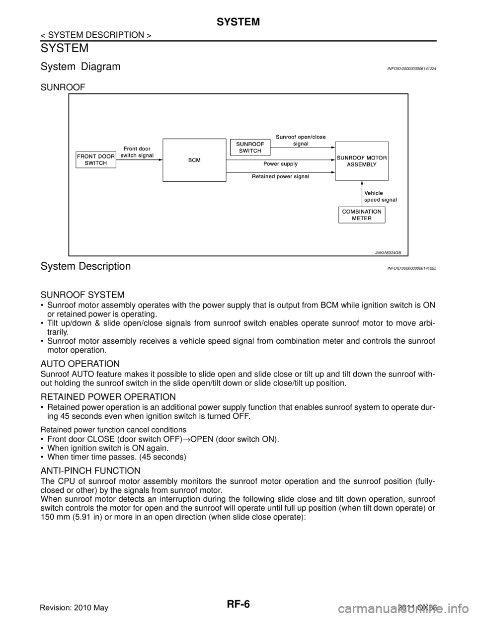
SUNROOF
System DescriptionINFOID:0000000006141225
SUNROOF SYSTEM
Sunroof motor assembly operates with the power supply that is output from BCM while ignition switch is ON
or retained power is operating.
Tilt up/down & slide open/close signals from sunroof s witch enables operate sunroof motor to move arbi-
trarily.
Sunroof motor assembly receives a vehicle speed signal from combination meter and controls the sunroof motor operation.
AUTO OPERATION
Sunroof AUTO feature makes it possible to slide open and slide close or tilt up and tilt down the sunroof with-
out holding the sunroof switch in the slide open/tilt down or slide close/tilt up position.
RETAINED POWER OPERATION
Retained power operation is an additional power supply function that enables sunroof system to operate dur-
ing 45 seconds even when ignition switch is turned OFF.
Retained power function cancel conditions
Front door CLOSE (door switch OFF) →OPEN (door switch ON).
When ignition switch is ON again.
When timer time passes. (45 seconds)
ANTI-PINCH FUNCTION
The CPU of sunroof motor assembly monitors the s unroof motor operation and the sunroof position (fully-
closed or other) by the signals from sunroof motor.
When sunroof motor detects an interruption during the following slide close and tilt down operation, sunroof
switch controls the motor for open and the sunroof will operate until full up position (when tilt down operate) or
150 mm (5.91 in) or more in an open direction (when slide close operate):
JMKIA5324GB
Revision: 2010 May2011 QX56
Page 4222 of 5598

RF-8
< ECU DIAGNOSIS INFORMATION >
SUNROOF SYSTEM
SUNROOF SYSTEM
Reference ValueINFOID:0000000006141227
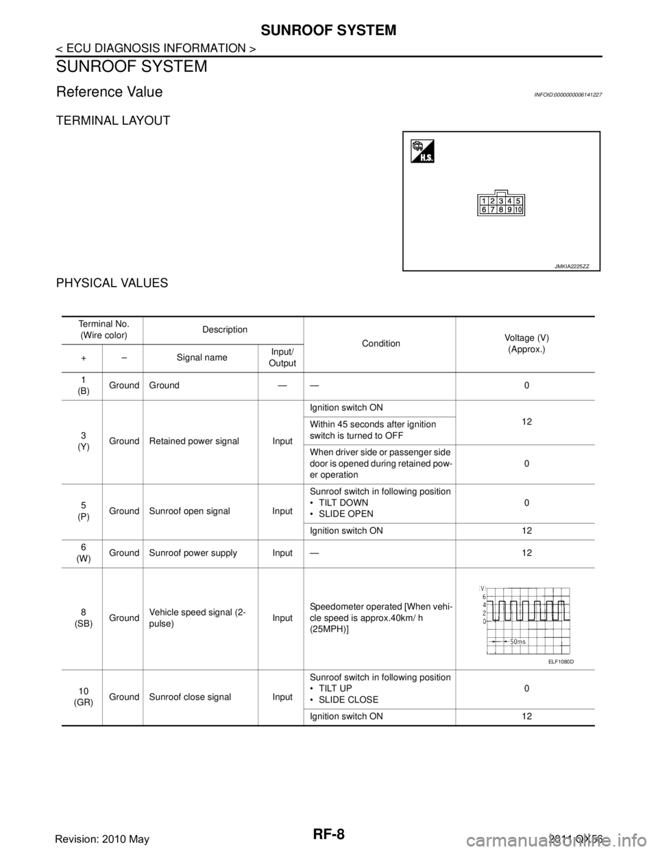
TERMINAL LAYOUT
PHYSICAL VALUES
JMKIA2225ZZ
Te r m i n a l N o .(Wire color) Description
ConditionVoltage (V)
(Approx.)
+ – Signal name Input/
Output
1
(B) Ground Ground — — 0
3
(Y) Ground Retained power signal Input Ignition switch ON
12
Within 45 seconds after ignition
switch is turned to OFF
When driver side or passenger side
door is opened during retained pow-
er operation 0
5
(P) Ground Sunroof open signal Input Sunroof switch in following position
TILT DOWN
SLIDE OPEN
0
Ignition switch ON 12
6
(W) Ground Sunroof power supply Input — 12
8
(SB) Ground Vehicle speed signal (2-
pulse)
InputSpeedometer operated [When vehi-
cle speed is approx.40km/ h
(25MPH)]
10
(GR) Ground Sunroof close signal Input Sunroof switch in following position
TILT UP
SLIDE CLOSE
0
Ignition switch ON 12
ELF1080D
Revision: 2010 May2011 QX56
Page 4234 of 5598

RF-20
< DTC/CIRCUIT DIAGNOSIS >
VEHICLE SPEED SIGNAL CIRCUIT
VEHICLE SPEED SIGNAL CIRCUIT
Component Function CheckINFOID:0000000006141233
1.CHECK SUNROOF MOTOR FUNCTION
Check tilt up/down & slide open/close operations with sunroof switch.
Is the inspection result normal?
YES >> GO TO 2.
NO >> Check sunroof switch. Refer to RF-21, "
DiagnosisProcedure".
2.CHECK SUNROOF MOTOR ASSEMBLY INPUT SIGNAL
1. Start engine.
2. Drive the vehicle at more than 40 km/h (25 MPH). CAUTION:
Always drive vehicle at a safe speed.
NOTE:
This procedure may be conducted with the drive wheel s lifted in the shop or by driving the vehicle.
If a road test is expected to be easier , it is unnecessary to lift the vehicle.
3. Check tilt up/down & slide open/clos e operations with sunroof switch.
Is the inspection result normal?
YES >> INSPECTION END
NO >> Refer to RF-20, "
DiagnosisProcedure".
Diagnosis ProcedureINFOID:0000000006141234
SUNROOF MOTOR ASSEMBLY
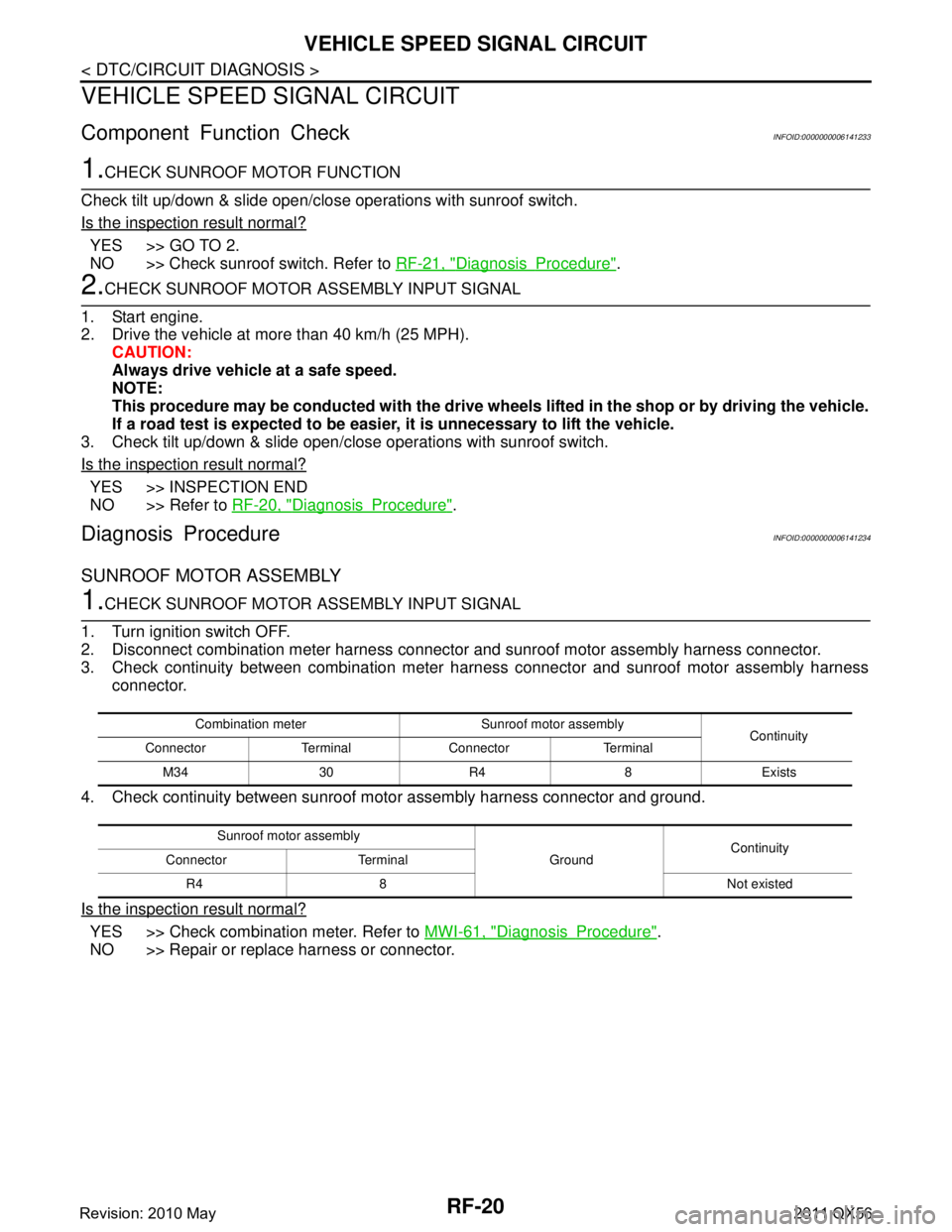
1.CHECK SUNROOF MOTOR ASSEMBLY INPUT SIGNAL
1. Turn ignition switch OFF.
2. Disconnect combination meter harness connector and sunroof motor assembly harness connector.
3. Check continuity between combination meter harness connector and sunroof motor assembly harness connector.
4. Check continuity between sunroof mo tor assembly harness connector and ground.
Is the inspection result normal?
YES >> Check combination meter. Refer to MWI-61, "DiagnosisProcedure".
NO >> Repair or replace harness or connector.
Combination meter Sunroof motor assembly Continuity
Connector Terminal Connector Terminal
M34 30 R4 8 Exists
Sunroof motor assembly GroundContinuity
Connector Terminal
R4 8 Not existed
Revision: 2010 May2011 QX56
Page 4235 of 5598

SUNROOF SWITCHRF-21
< DTC/CIRCUIT DIAGNOSIS >
C
DE
F
G H
I
J
L
M A
B
RF
N
O P
SUNROOF SWITCH
Component Function CheckINFOID:0000000006141235
1.CHECK SUNROOF MOTOR FUNCTION
Check tilt up/down & slide open/close operations with sunroof switch.
Is the inspection result normal?
YES >> INSPECTION END
NO >> Refer to RF-21, "
DiagnosisProcedure".
Diagnosis ProcedureINFOID:0000000006141236
1.PERFORM INITIALIZATION PROCEDURE
1. Initialization procedure is executed and operation is confirmed. Refer to RF-17, "
ADDITIONAL SERVICE
WHEN REPLACING CONTROL UNIT : Special Repair Requirement".
2. Check tilt up/down & slide open/close operations with sunroof switch.
Is the inspection result normal?
YES >> INSPECTION END
NO >> GO TO 2.
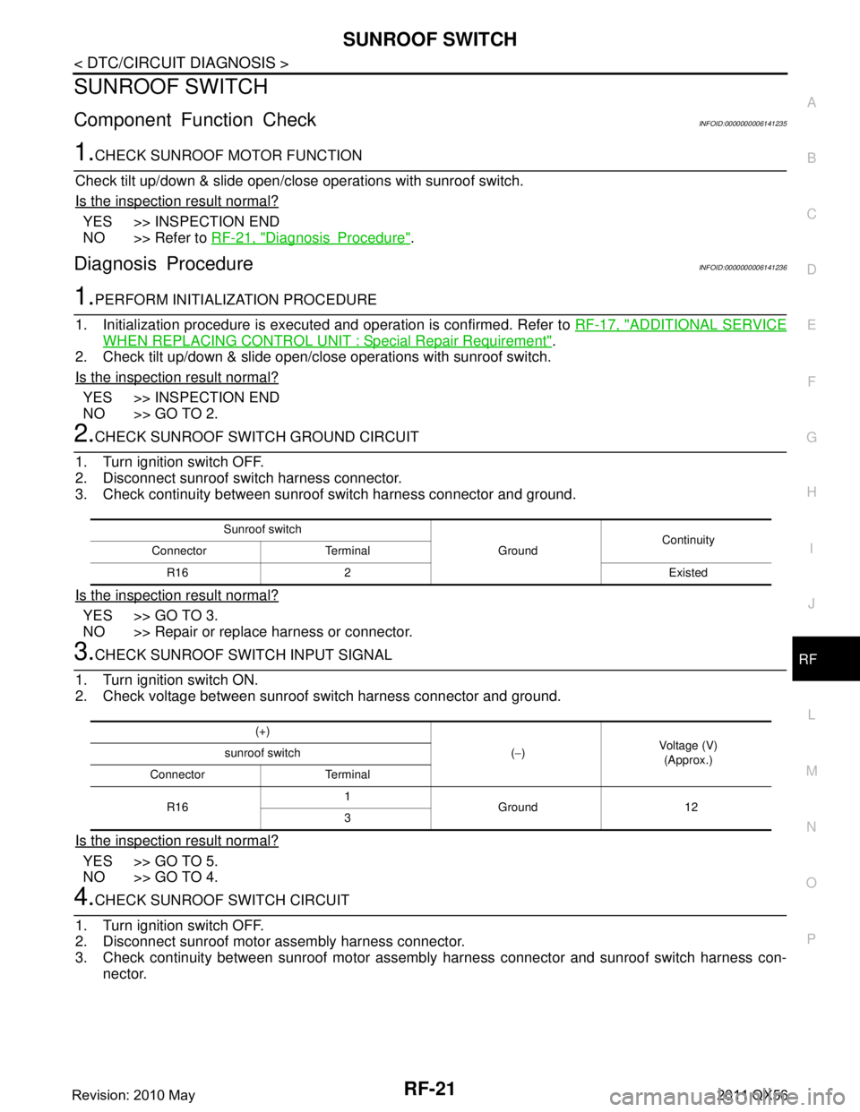
2.CHECK SUNROOF SWITCH GROUND CIRCUIT
1. Turn ignition switch OFF.
2. Disconnect sunroof switch harness connector.
3. Check continuity between sunroof switch harness connector and ground.
Is the inspection result normal?
YES >> GO TO 3.
NO >> Repair or replace harness or connector.
3.CHECK SUNROOF SWITCH INPUT SIGNAL
1. Turn ignition switch ON.
2. Check voltage between sunroof switch harness connector and ground.
Is the inspection result normal?
YES >> GO TO 5.
NO >> GO TO 4.
4.CHECK SUNROOF SWITCH CIRCUIT
1. Turn ignition switch OFF.
2. Disconnect sunroof motor assembly harness connector.
3. Check continuity between sunroof motor assemb ly harness connector and sunroof switch harness con-
nector.
Sunroof switch
GroundContinuity
Connector Terminal
R16 2 Existed
(+) (− ) Voltage (V)
(Approx.)
sunroof switch
Connector Terminal
R16 1
Ground 12
3
Revision: 2010 May2011 QX56