2011 INFINITI QX56 turn signal
[x] Cancel search: turn signalPage 4447 of 5598
![INFINITI QX56 2011 Factory Service Manual
U1000 CAN COMM CIRCUITSCS-87
< DTC/CIRCUIT DIAGNOSIS > [AIR LEVELIZER CONTROL SYSTEM]
C
D
F
G H
I
J
K L
M A
B
SCS
N
O P
U1000 CAN COMM CIRCUIT
DescriptionINFOID:0000000006256082
CAN (Controller Area INFINITI QX56 2011 Factory Service Manual
U1000 CAN COMM CIRCUITSCS-87
< DTC/CIRCUIT DIAGNOSIS > [AIR LEVELIZER CONTROL SYSTEM]
C
D
F
G H
I
J
K L
M A
B
SCS
N
O P
U1000 CAN COMM CIRCUIT
DescriptionINFOID:0000000006256082
CAN (Controller Area](/manual-img/42/57033/w960_57033-4446.png)
U1000 CAN COMM CIRCUITSCS-87
< DTC/CIRCUIT DIAGNOSIS > [AIR LEVELIZER CONTROL SYSTEM]
C
D
F
G H
I
J
K L
M A
B
SCS
N
O P
U1000 CAN COMM CIRCUIT
DescriptionINFOID:0000000006256082
CAN (Controller Area Network) is a serial communication line for real-time application. It is an on-vehicle mul-
tiplex communication line with high data communica tion speed and excellent malfunction detection ability.
Many electronic control units are equipped onto a vehicl e, and each control unit shares information and links
with other control units during operation (not independently ). In CAN communication, control units are con-
nected with 2 communication lines (CAN-H line, CAN-L li ne) allowing a high rate of information transmission
with less wiring. Each control unit transmits/recei ves data but selectively reads required data only.
DTC LogicINFOID:0000000006256083
DTC DETECTION LOGIC
DTC CONFIRMATION PROCEDURE
1.PRECONDITIONING
If “DTC CONFIRMATION PROCEDURE” is previously c onducted, always turn ignition switch OFF and wait at
least 10 seconds before performing the next test.
>> GO TO 2.
2.CHECK DTC DETECTION
With CONSULT-III
1. Start the engine.
2. Run engine for at least 2 cons ecutive seconds at idle speed.
3. Perform “Self Diagnostic Results” in “E-SUS”.
Is
“U1000” detected?
YES >> Go to SCS-87, "Diagnosis Procedure".
NO >> INSPECTION END
Diagnosis ProcedureINFOID:0000000006256084
Go to LAN-18, "Trouble Diagnosis Flow Chart".
DTC Display itemI Malfunction detected condition Possible cause
U1000 CAN COMM CIRCUIT Air levelizer control module is not transmitting or re-
ceiving CAN communication signal for 2 seconds or
more. Harness or connectors
(CAN communication line is open or
shorted.)
Air levelizer control module
Revision: 2010 May2011 QX56
Page 4450 of 5598
![INFINITI QX56 2011 Factory Service Manual
SCS-90
< DTC/CIRCUIT DIAGNOSIS >[AIR LEVELIZER CONTROL SYSTEM]
CK SUSP INDICATOR LAMP CIRCUIT
CK SUSP INDICATOR LAMP CIRCUIT
DescriptionINFOID:0000000006256089
Air levelizer control module transmits INFINITI QX56 2011 Factory Service Manual
SCS-90
< DTC/CIRCUIT DIAGNOSIS >[AIR LEVELIZER CONTROL SYSTEM]
CK SUSP INDICATOR LAMP CIRCUIT
CK SUSP INDICATOR LAMP CIRCUIT
DescriptionINFOID:0000000006256089
Air levelizer control module transmits](/manual-img/42/57033/w960_57033-4449.png)
SCS-90
< DTC/CIRCUIT DIAGNOSIS >[AIR LEVELIZER CONTROL SYSTEM]
CK SUSP INDICATOR LAMP CIRCUIT
CK SUSP INDICATOR LAMP CIRCUIT
DescriptionINFOID:0000000006256089
Air levelizer control module transmits CK SUSP indicator lamp signal to combination meter via CAN communi-
cation, when setting of standard vehicle height is incomplete. Based on the signal, combination meter turns
CK SUSP indicator lamp ON.
Component Function CheckINFOID:0000000006256090
1.CHECK CK SUSP INDICATOR LAMP OPERATION
CONSULT-III
1. Turn ignition switch ON.
2. Select “WARNING LAMP” in “Active Test” in “E-SUS”.
3. While operating test item, check that the CK SUSP indicator lamp activates.
Is the inspection result normal?
YES >> INSPECTION END
NO >> Refer to SCS-90, "
Diagnosis Procedure".
Diagnosis ProcedureINFOID:0000000006256091
1.PERFORM SELF-DIAGNOSIS
CONSULT-III
1. Turn ignition switch ON.
2. Select “Self Diagnostic Result” in “E-SUS”.
Are any DTC detected?
YES >> Refer to SCS-59, "DTC Index".
NO >> GO TO 2.
2.CHECK COMBINATION METER
Check combination meter. Refer to MWI-29, "
On Board Diagnosis Function".
Is the inspection result normal?
YES >> Replace the air levelizer control module. Refer to SCS-94, "Removal and Installation".
NO >> Repair or replace the combination meter. Refer to MWI-85, "
Removal and Installation".
ON : CK SUSP indicator lamp turns ON
OFF : CK SUSP indicator lamp turns OFF
Revision: 2010 May2011 QX56
Page 4526 of 5598

POWER SUPPLY AND GROUND CIRCUITSE-67
< DTC/CIRCUIT DIAGNOSIS >
C
DE
F
G H
I
K L
M A
B
SE
N
O P
DTC/CIRCUIT DIAGNOSIS
POWER SUPPLY AND GROUND CIRCUIT
CLIMATE CONTROLLED SEAT CONTROL UNIT
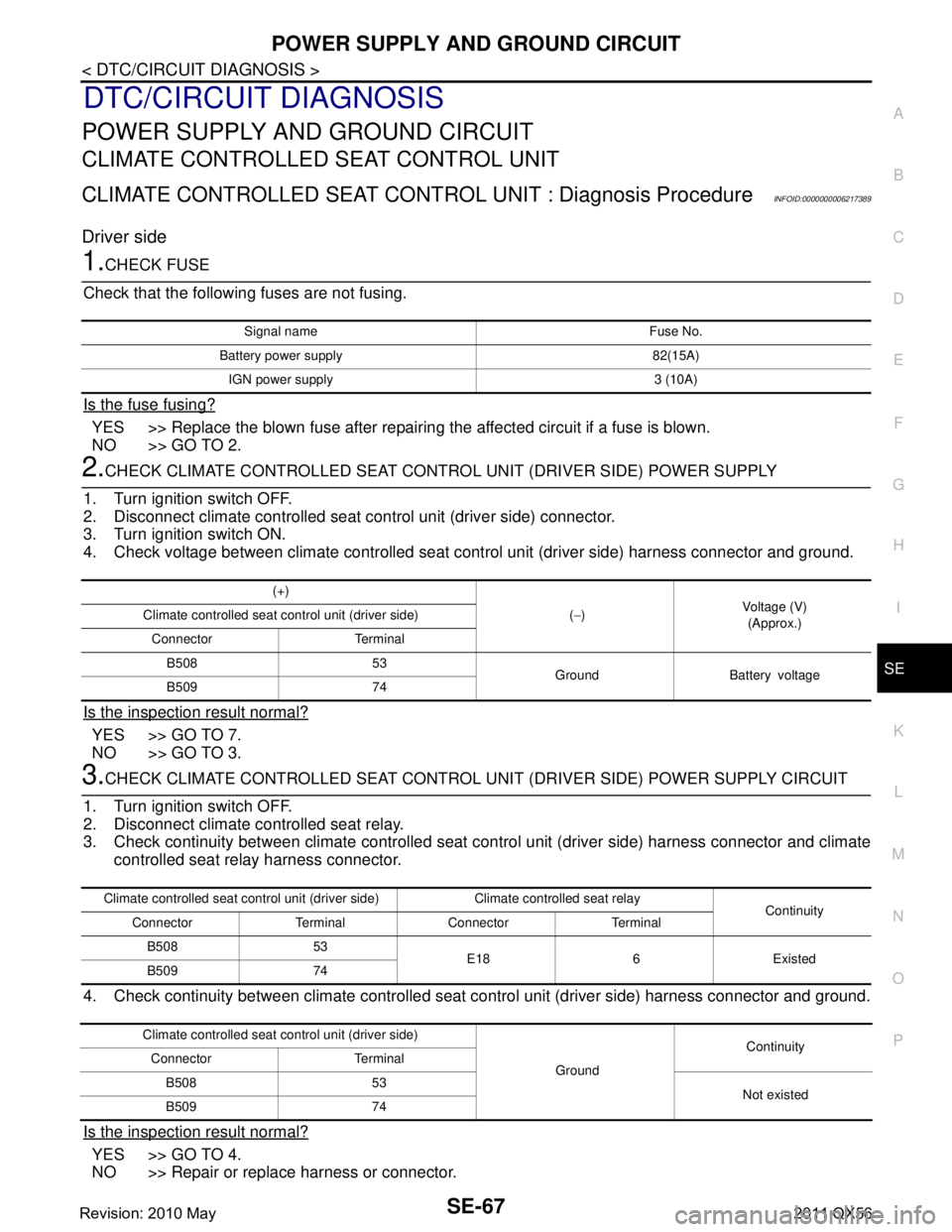
CLIMATE CONTROLLED SEAT CONT ROL UNIT : Diagnosis ProcedureINFOID:0000000006217389
Driver side
1.CHECK FUSE
Check that the following fuses are not fusing.
Is the fuse fusing?
YES >> Replace the blown fuse after repairing the affected circuit if a fuse is blown.
NO >> GO TO 2.
2.CHECK CLIMATE CONTROLLED SEAT CONTRO L UNIT (DRIVER SIDE) POWER SUPPLY
1. Turn ignition switch OFF.
2. Disconnect climate controlled seat control unit (driver side) connector.
3. Turn ignition switch ON.
4. Check voltage between climate controlled seat c ontrol unit (driver side) harness connector and ground.
Is the inspection result normal?
YES >> GO TO 7.
NO >> GO TO 3.
3.CHECK CLIMATE CONTROLLED SEAT CONTROL UNI T (DRIVER SIDE) POWER SUPPLY CIRCUIT
1. Turn ignition switch OFF.
2. Disconnect climate controlled seat relay.
3. Check continuity between climate controlled seat control unit (driver side) harness connector and climate
controlled seat relay harness connector.
4. Check continuity between climate controlled seat control unit (driver side) harness connector and ground.
Is the inspection result normal?
YES >> GO TO 4.
NO >> Repair or replace harness or connector.
Signal name Fuse No.
Battery power supply 82(15A) IGN power supply 3 (10A)
(+) (− ) Voltage (V)
(Approx.)
Climate controlled seat co
ntrol unit (driver side)
Connector Terminal B508 53 Ground Battery voltage
B509 74
Climate controlled seat control unit (dri ver side) Climate controlled seat relay
Continuity
Connector Terminal Connector Terminal
B508 53 E18 6 Existed
B509 74
Climate controlled seat co ntrol unit (driver side)
GroundContinuity
Connector Terminal
B508 53 Not existed
B509 74
Revision: 2010 May2011 QX56
Page 4528 of 5598

POWER SUPPLY AND GROUND CIRCUITSE-69
< DTC/CIRCUIT DIAGNOSIS >
C
DE
F
G H
I
K L
M A
B
SE
N
O P
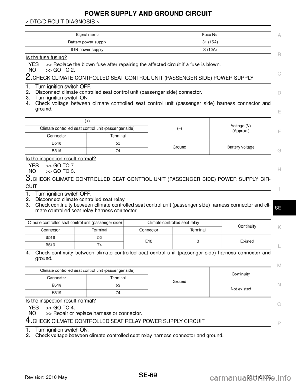
Is the fuse fusing?
YES >> Replace the blown fuse after repairing the affected circuit if a fuse is blown.
NO >> GO TO 2.
2.CHECK CLIMATE CONTROLLED SEAT CONTROL UNIT (PASSENGER SIDE) POWER SUPPLY
1. Turn ignition switch OFF.
2. Disconnect climate controlled seat c ontrol unit (passenger side) connector.
3. Turn ignition switch ON.
4. Check voltage between climate controlled seat control unit (passenger side) harness connector and
ground.
Is the inspection result normal?
YES >> GO TO 7.
NO >> GO TO 3.
3.CHECK CLIMATE CONTROLLED SEAT CONTROL UNI T (PASSENGER SIDE) POWER SUPPLY CIR-
CUIT
1. Turn ignition switch OFF.
2. Disconnect climate controlled seat relay.
3. Check continuity between climate controlled seat control unit (passenger side) harness connector and cli-
mate controlled seat relay harness connector.
4. Check continuity between climate controlled seat control unit (passenger side) harness connector and
ground.
Is the inspection result normal?
YES >> GO TO 4.
NO >> Repair or replace harness or connector.
4.CHECK CILMATE CONTROLLED SEAT RELAY POWER SUPPLY CIRCUIT
1. Turn ignition switch ON.
2. Check voltage between climate controll ed seat relay harness connector and ground.
Signal name Fuse No.
Battery power supply 81 (15A) IGN power supply 3 (10A)
(+) (− ) Voltage (V)
(Approx.)
Climate controlled seat control unit (passenger side)
Connector TerminalB518 53 Ground Battery voltage
B519 74
Climate controlled seat control unit (passenger side) Climate controlled seat relay Continuity
Connector Terminal Connector Terminal
B518 53 E18 3 Existed
B519 74
Climate controlled seat control unit (passenger side)
GroundContinuity
Connector Terminal
B518 53 Not existed
B519 74
Revision: 2010 May2011 QX56
Page 4531 of 5598

SE-72
< DTC/CIRCUIT DIAGNOSIS >
CLIMATE CONTROLLED SEAT SWITCH
CLIMATE CONTROLLED SEAT SWITCH
Component Function CheckINFOID:0000000006217391
1.CHECK CLIMATE CONTROLLED SEAT SWITCH FUNCTION
Check that climate controlled seat activates when operating climate controlled seat control switch.
Is the inspection result normal?
YES >> Climate controlled seat switch is OK.
NO >> Refer to SE-72, "
Diagnosis Procedure".
Diagnosis ProcedureINFOID:0000000006217392
1.CHECK CLIMATE CONTROLLED SEAT CONTROL UNIT INPUT SIGNAL
1. Turn ignition switch ON.
2. Check voltage between climate controlled seat control unit harness connector and ground.
Is the inspection result normal?
YES >> Climate controlled seat switch circuit is OK.
NO-1 HEAT or COOL mode is NG>>GO TO 2.
NO-2 HEAT and COOL modes are NG>>GO TO 3.
2.CHECK CLIMATE CONTROLLED SEAT SWITCH CIRCUIT
1. Turn ignition switch OFF.
2. Disconnect climate controlled seat switch connecto r and climate controlled seat control unit connector.
3. Check continuity between climate controlled seat switch harness connector and climate controlled seat
control unit harness connector.
(+)
(–) Condition Voltage (V)
(Approx.)
Climate controlled seat control unit
Connector Terminal
Driver side B508 54
Ground Climate controlled seat
switch (driver side)
COOL
HI 2.6 - 4.2
MID 1.6 - 2.5
LO 0.8 - 1.5
OFF 0
55 HEATHI 2.6 - 4.2
MID 1.6 - 2.5
LO 0.8 - 1.5
OFF 0
Passenger side B518 54
Climate controlled seat
switch (passenger seat) COOL
HI 2.6 - 4.2
MID 1.6 - 2.5
LO 0.8 - 1.5
OFF 0
55 HEATHI 2.6 - 4.2
MID 1.6 - 2.5
LO 0.8 - 1.5
OFF 0
Revision: 2010 May2011 QX56
Page 4534 of 5598

SEATBACK THERMAL ELECTRIC UNITSE-75
< DTC/CIRCUIT DIAGNOSIS >
C
DE
F
G H
I
K L
M A
B
SE
N
O P
SEATBACK THERMAL ELECTRIC UNIT
Component Function CheckINFOID:0000000006217394
1.CHECK SEATBACK THERMAL ELECTRIC UNIT FUNCTION
Check whether or not the temperatur e of the seatback thermal electric unit changes in accordance with the
HEAT or COOL switch operation of the climate controlled seat control switch.
Is the inspection result normal?
YES >> Seatback thermal electric unit function is OK.
NO >> Refer to SE-75, "
Diagnosis Procedure".
Diagnosis ProcedureINFOID:0000000006217395
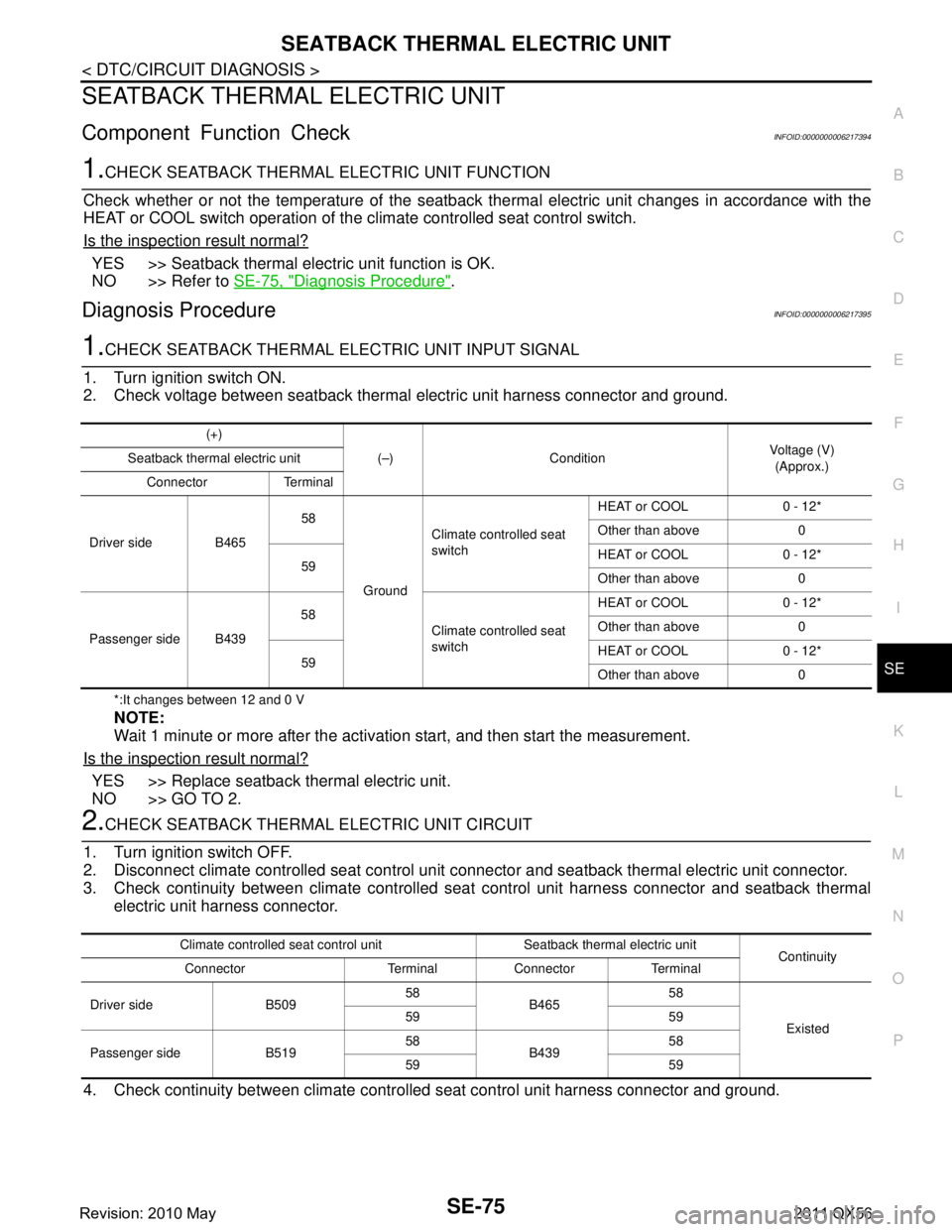
1.CHECK SEATBACK THERMAL ELECTRIC UNIT INPUT SIGNAL
1. Turn ignition switch ON.
2. Check voltage between seatback thermal electric unit harness connector and ground.
*:It changes between 12 and 0 V
NOTE:
Wait 1 minute or more after the activation start, and then start the measurement.
Is the inspection result normal?
YES >> Replace seatback thermal electric unit.
NO >> GO TO 2.
2.CHECK SEATBACK THERMAL ELECTRIC UNIT CIRCUIT
1. Turn ignition switch OFF.
2. Disconnect climate controlled seat control unit c onnector and seatback thermal electric unit connector.
3. Check continuity between climate controlled s eat control unit harness connector and seatback thermal
electric unit harness connector.
4. Check continuity between climate controll ed seat control unit harness connector and ground.
(+)
(–) Condition Voltage (V)
(Approx.)
Seatback thermal electric unit
Connector Terminal
Driver side B465 58
Ground Climate controlled seat
switch
HEAT or COOL 0 - 12*
Other than above 0
59 HEAT or COOL 0 - 12*
Other than above 0
Passenger side B439 58
Climate controlled seat
switch HEAT or COOL 0 - 12*
Other than above 0
59 HEAT or COOL 0 - 12*
Other than above 0
Climate controlled seat control unit Seatback thermal electric unit
Continuity
Connector Terminal Connector Terminal
Driver side B509 58
B465 58
Existed
59 59
Passenger side B519 58
B439 58
59 59
Revision: 2010 May2011 QX56
Page 4536 of 5598

SEATBACK THERMAL ELECTRIC UNIT SENSORSE-77
< DTC/CIRCUIT DIAGNOSIS >
C
DE
F
G H
I
K L
M A
B
SE
N
O P
SEATBACK THERMAL ELECTRIC UNIT SENSOR
Component Function CheckINFOID:0000000006217396
1.CHECK SEATBACK THERMAL ELECTRIC UNIT SENSOR FUNCTION
Check whether or not the temperatur e of the seatback thermal electric unit changes in accordance with the
HEAT or COOL switch operation of the climate controlled seat control switch.
Is the inspection result normal?
YES >> INSPECTION END
NO >> Refer to SE-77, "
Diagnosis Procedure".
Diagnosis ProcedureINFOID:0000000006217397
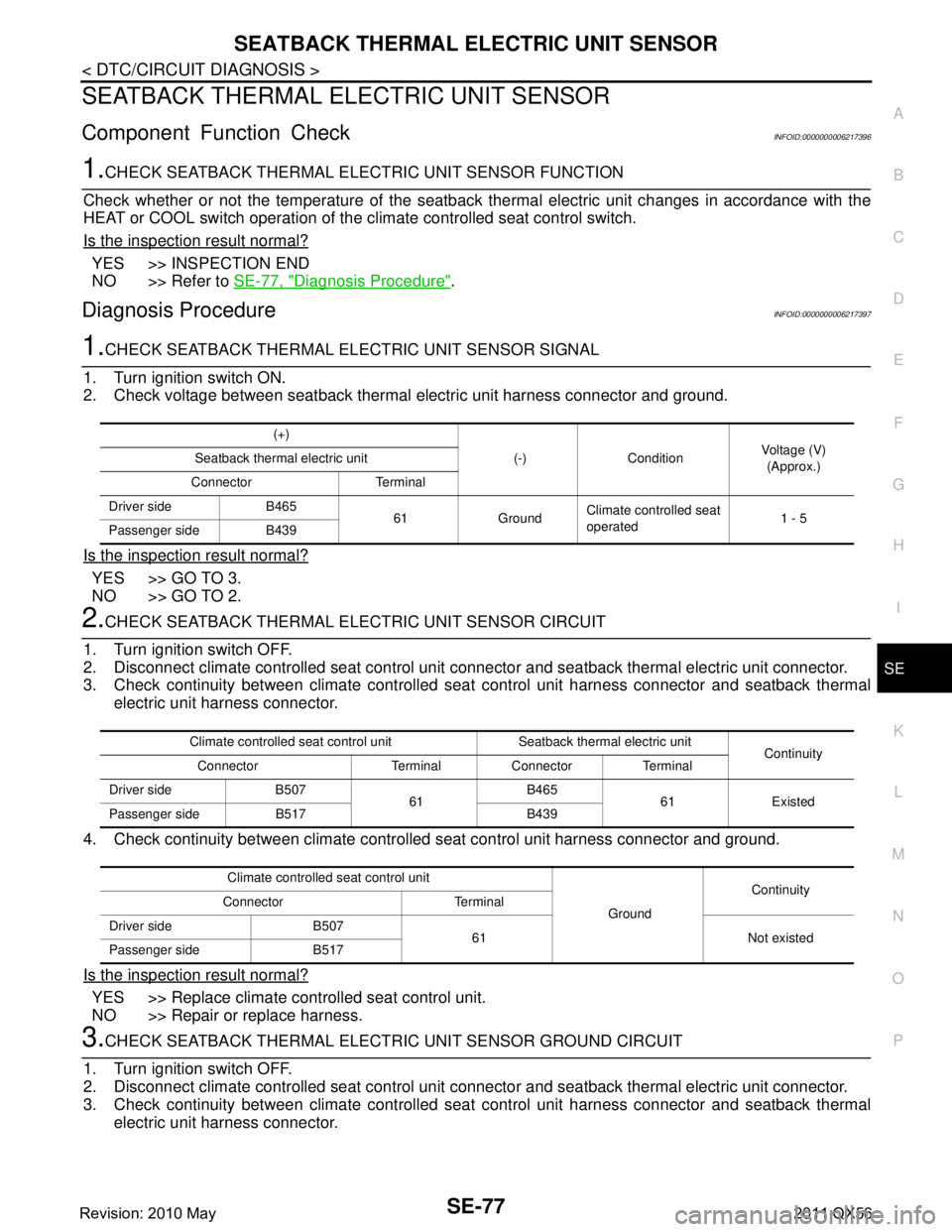
1.CHECK SEATBACK THERMAL ELECTRIC UNIT SENSOR SIGNAL
1. Turn ignition switch ON.
2. Check voltage between seatback thermal electric unit harness connector and ground.
Is the inspection result normal?
YES >> GO TO 3.
NO >> GO TO 2.
2.CHECK SEATBACK THERMAL ELECTRIC UNIT SENSOR CIRCUIT
1. Turn ignition switch OFF.
2. Disconnect climate controlled seat control unit c onnector and seatback thermal electric unit connector.
3. Check continuity between climate controlled s eat control unit harness connector and seatback thermal
electric unit harness connector.
4. Check continuity between climate controll ed seat control unit harness connector and ground.
Is the inspection result normal?
YES >> Replace climate controlled seat control unit.
NO >> Repair or replace harness.
3.CHECK SEATBACK THERMAL ELECTRIC UNIT SENSOR GROUND CIRCUIT
1. Turn ignition switch OFF.
2. Disconnect climate controlled seat control unit c onnector and seatback thermal electric unit connector.
3. Check continuity between climate controlled s eat control unit harness connector and seatback thermal
electric unit harness connector.
(+)
(-) Condition Voltage (V)
(Approx.)
Seatback thermal electric unit
Connector Terminal
Driver side B465 61 GroundClimate controlled seat
operated
1 - 5
Passenger side B439
Climate controlled seat control unit Seatback thermal electric unit Continuity
Connector Terminal Connector Terminal
Driver side B507 61B465
61 Existed
Passenger side B517 B439
Climate controlled seat control unit GroundContinuity
Connector Terminal
Driver side B507 61 Not existed
Passenger side B517
Revision: 2010 May2011 QX56
Page 4538 of 5598

SEAT CUSHION THERMAL ELECTRIC UNITSE-79
< DTC/CIRCUIT DIAGNOSIS >
C
DE
F
G H
I
K L
M A
B
SE
N
O P
SEAT CUSHION THERMAL ELECTRIC UNIT
Component Function CheckINFOID:0000000006217399
1.CHECK SEAT CUSHION THERMAL ELECTRIC UNIT FUNCTION
Check whether or not the temperature of the seat cush ion thermal electric unit changes in accordance with the
HEAT or COOL switch operation of the climate controlled seat control switch.
Is the inspection result normal?
YES >> Seatback thermal electric unit function is OK.
NO >> Refer to SE-79, "
Diagnosis Procedure".
Diagnosis ProcedureINFOID:0000000006217400
1.CHECK SEAT CUSHION THERMAL ELECTRIC UNIT SIGNAL
1. Turn ignition switch ON.
2. Check voltage between seat cushion ther mal electric unit harness connector and ground.
*:It changes between 12 and 0 V
NOTE:
Wait 1 minute or more after the activation start, and then start the measurement.
Is the inspection result normal?
YES >> Replace seat cushion thermal electric unit.
NO >> GO TO 2.
2.CHECK SEAT CUSHION THERMAL ELECTRIC UNIT CIRCUIT
1. Turn ignition switch OFF.
2. Disconnect climate controlled seat control unit connec tor and seat cushion thermal electric unit connector.
3. Check continuity between climate controlled seat control unit harness connector and seat cushion thermal
electric unit harness connector.
4. Check continuity between climate controll ed seat control unit harness connector and ground.
(+)
(–) Condition Voltage (V)
(Approx.)
Seat cushion thermal electric unit
Connector Terminal
Driver side B505 67
Ground Climate controlled seat
switch
HEAT or COOL 0 - 12*
Other than above 0
68 HEAT or COOL 0 - 12*
Other than above 0
Passenger side B515 67
Climate controlled seat
switch HEAT or COOL 0 - 12*
Other than above 0
68 HEAT or COOL 0 - 12*
Other than above 0
Climate controlled seat control unit Seat cushion thermal electric unit
Continuity
Connector Terminal Connector Terminal
Driver side B509 67
B505 67
Existed
68 68
Passenger side B519 67
B515 67
68 68
Revision: 2010 May2011 QX56