2011 INFINITI QX56 turn signal
[x] Cancel search: turn signalPage 4331 of 5598
SBC-34
< DTC/CIRCUIT DIAGNOSIS >
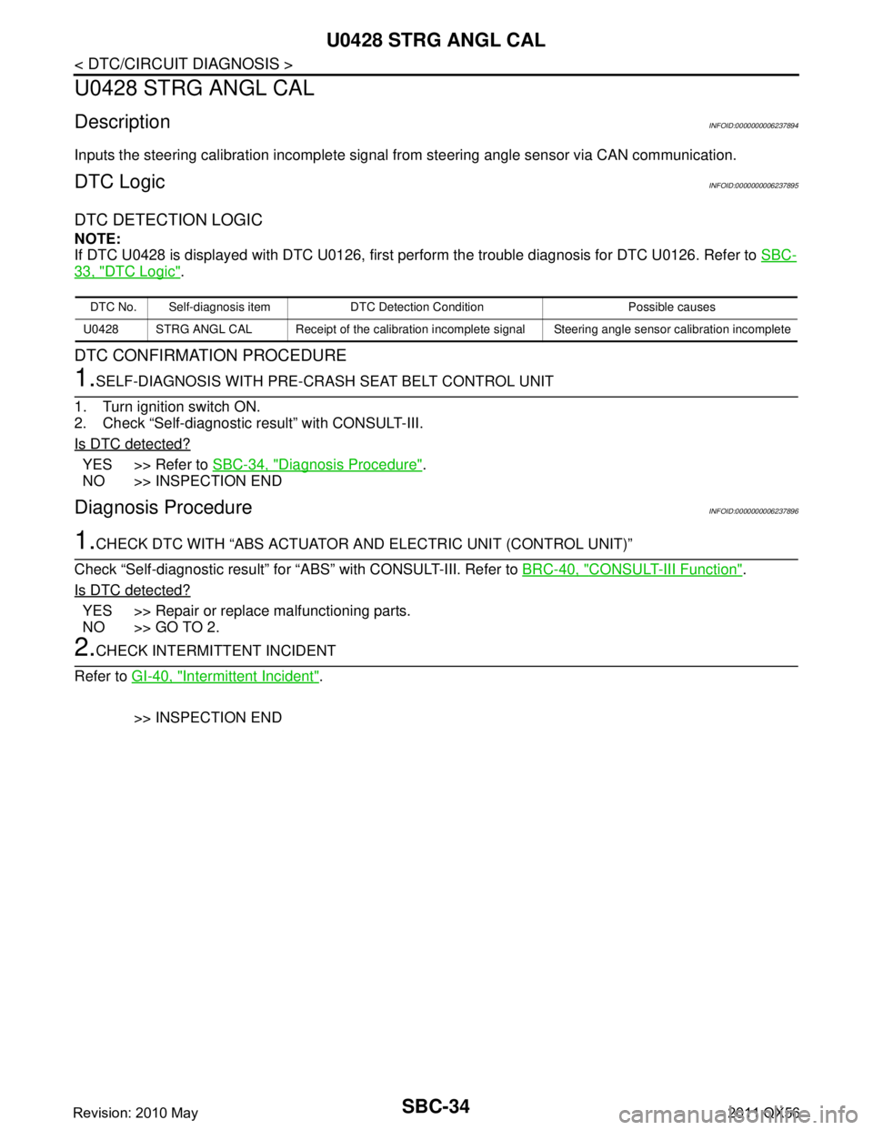
U0428 STRG ANGL CAL
U0428 STRG ANGL CAL
DescriptionINFOID:0000000006237894
Inputs the steering calibration incomplete signal from steering angle sensor via CAN communication.
DTC LogicINFOID:0000000006237895
DTC DETECTION LOGIC
NOTE:
If DTC U0428 is displayed with DTC U0126, first perform the trouble diagnosis for DTC U0126. Refer to SBC-
33, "DTC Logic".
DTC CONFIRMATION PROCEDURE
1.SELF-DIAGNOSIS WITH PRE-CRASH SEAT BELT CONTROL UNIT
1. Turn ignition switch ON.
2. Check “Self-diagnostic result” with CONSULT-III.
Is DTC detected?
YES >> Refer to SBC-34, "Diagnosis Procedure".
NO >> INSPECTION END
Diagnosis ProcedureINFOID:0000000006237896
1.CHECK DTC WITH “ABS ACTUATOR A ND ELECTRIC UNIT (CONTROL UNIT)”
Check “Self-diagnostic result” for “ABS” with CONSULT-III. Refer to BRC-40, "
CONSULT-III Function".
Is DTC detected?
YES >> Repair or replace malfunctioning parts.
NO >> GO TO 2.
2.CHECK INTERMITTENT INCIDENT
Refer to GI-40, "
Intermittent Incident".
>> INSPECTION END
DTC No. Self-diagnosis item DTC Detection Condition Possible causes
U0428 STRG ANGL CAL Receipt of the calibration incomplete signal Steering angle sensor calibration incomplete
Revision: 2010 May2011 QX56
Page 4335 of 5598

SBC-38
< DTC/CIRCUIT DIAGNOSIS >
B2453 BR STROKE SEN CIRC
B2453 BR STROKE SEN CIRC
DTC LogicINFOID:0000000006237903
DTC DETECTION LOGIC
DTC CONFIRMATION PROCEDURE
1.SELF-DIAGNOSIS WITH PRE-CRASH SEAT BELT CONTROL UNIT
1. Turn ignition switch ON.
2. Check “Self-diagnostic result” with CONSULT-III.
Is DTC detected?
YES >> Refer to SBC-38, "Diagnosis Procedure".
NO >> INSPECTION END
Diagnosis ProcedureINFOID:0000000006237904
1.CHECK PRE-CRASH SEAT BELT CONTROL UNIT INPUT SIGNAL
1. Turn ignition switch ON.
2. Select “BRK PEDAL SNSR1” and “BRK PEDAL SNSR2” in “DATA MONITOR” mode with CONSULT-III.
3. Check “BRK PEDAL SNSR1” and “BRK PEDAL SNSR2” indication under the following conditions.
Is the inspection result normal?
YES >> GO TO 6.
NO >> GO TO 2.
2.CHECK BRAKE PEDAL STROKE SENSOR POWER SUPPLY
1. Turn ignition switch OFF.
2. Disconnect brake pedal stroke sensor harness connector.
3. Check voltage between brake pedal stroke sensor harness connector and ground.
Is the inspection result normal?
YES >> GO TO 4.
NO >> GO TO 3.
3.CHECK BRAKE PEDAL STROKE SENSOR POWER SUPPLY CIRCUIT
1. Disconnect pre-crash seat belt contro l unit (driver side) harness connector.
2. Check continuity between pre-crash seat belt c ontrol unit (driver side) harness connector and brake pedal
stroke sensor harness connector.
DTC No. Self-diagnosis item DTC Detection Condition Possible causes
B2453 BR STROKE SEN CIRC Circuit of brake pedal stroke sensor out-
put is open or shorted Harness or connectors
(The sensor circuit is open or shorted)
Pre-crash seat belt co ntrol unit (driver side)
Brake pedal stroke sensor
Monitor item Condition Voltage (V)
(Approx.)
BRK PEDAL SNSR1 Brake released → depressed 1
→ 4
BRK PEDAL SNSR2 4 → 1
Brake pedal stroke sensor
GroundVoltage (V)
(Approx.)
Connector Terminal
E 111 2 5
Pre-crash seat belt control unit (driver side) Brake pedal stroke sensor Continuity
Connector Terminal Connector Terminal
B9 10 E111 2 Existed
Revision: 2010 May2011 QX56
Page 4342 of 5598
B2458 LOCAL COMMSBC-45
< DTC/CIRCUIT DIAGNOSIS >
C
DE
F
G
I
J
K L
M A
B
SBC
N
O P
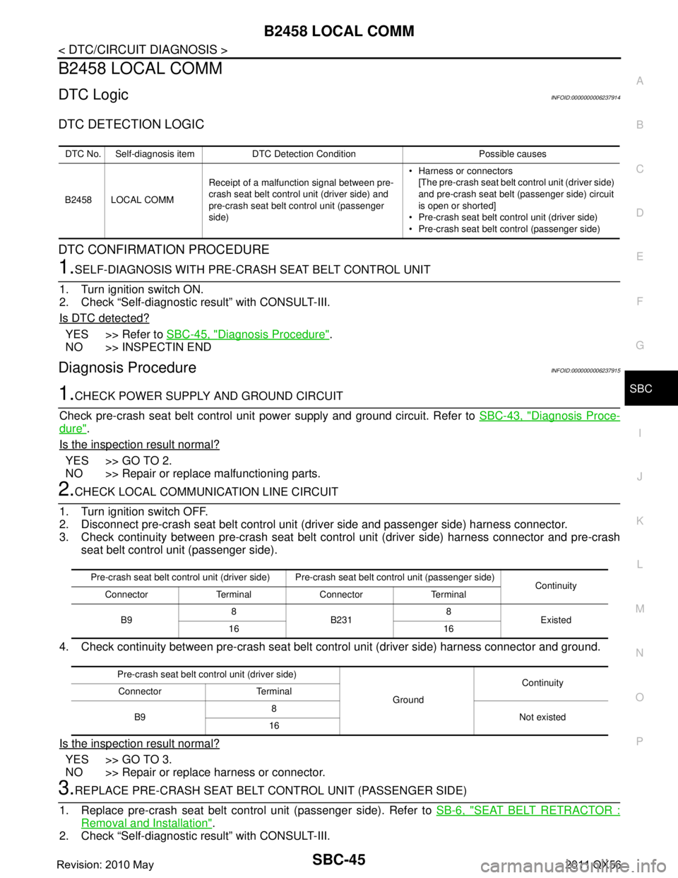
B2458 LOCAL COMM
DTC LogicINFOID:0000000006237914
DTC DETECTION LOGIC
DTC CONFIRMATION PROCEDURE
1.SELF-DIAGNOSIS WITH PRE-CRASH SEAT BELT CONTROL UNIT
1. Turn ignition switch ON.
2. Check “Self-diagnostic result” with CONSULT-III.
Is DTC detected?
YES >> Refer to SBC-45, "Diagnosis Procedure".
NO >> INSPECTIN END
Diagnosis ProcedureINFOID:0000000006237915
1.CHECK POWER SUPPLY AND GROUND CIRCUIT
Check pre-crash seat belt control unit power supply and ground circuit. Refer to SBC-43, "
Diagnosis Proce-
dure".
Is the inspection result normal?
YES >> GO TO 2.
NO >> Repair or replace malfunctioning parts.
2.CHECK LOCAL COMMUNICATION LINE CIRCUIT
1. Turn ignition switch OFF.
2. Disconnect pre-crash seat belt control unit (driver side and passenger side) harness connector.
3. Check continuity between pre-crash seat belt cont rol unit (driver side) harness connector and pre-crash
seat belt control unit (passenger side).
4. Check continuity between pre-crash seat belt control unit (driver side) harness connector and ground.
Is the inspection result normal?
YES >> GO TO 3.
NO >> Repair or replace harness or connector.
3.REPLACE PRE-CRASH SEAT BELT CONTROL UNIT (PASSENGER SIDE)
1. Replace pre-crash seat belt control unit (passenger side). Refer to SB-6, "
SEAT BELT RETRACTOR :
Removal and Installation".
2. Check “Self-diagnostic result” with CONSULT-III.
DTC No. Self-diagnosis item DTC Detection Condition Possible causes
B2458 LOCAL COMM Receipt of a malfunction signal between pre-
crash seat belt control unit (driver side) and
pre-crash seat belt control unit (passenger
side) Harness or connectors
[The pre-crash seat belt control unit (driver side)
and pre-crash seat belt (passenger side) circuit
is open or shorted]
Pre-crash seat belt control unit (driver side)
Pre-crash seat belt control (passenger side)
Pre-crash seat belt control unit (driver side) Pre -crash seat belt control unit (passenger side)
Continuity
Connector Terminal Connector Terminal
B9 8
B231 8
Existed
16 16
Pre-crash seat belt control unit (driver side) GroundContinuity
Connector Terminal
B9 8
Not existed
16
Revision: 2010 May2011 QX56
Page 4344 of 5598
B2461 VHCL SPEED SIGNALSBC-47
< DTC/CIRCUIT DIAGNOSIS >
C
DE
F
G
I
J
K L
M A
B
SBC
N
O P
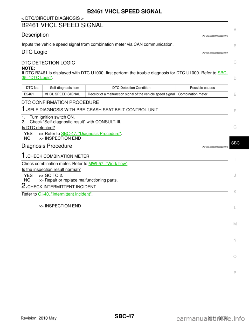
B2461 VHCL SPEED SIGNAL
DescriptionINFOID:0000000006237916
Inputs the vehicle speed signal from combination meter via CAN communication.
DTC LogicINFOID:0000000006237917
DTC DETECTION LOGIC
NOTE:
If DTC B2461 is displayed with DTC U1000, first per form the trouble diagnosis for DTC U1000. Refer to SBC-
35, "DTC Logic".
DTC CONFIRMATION PROCEDURE
1.SELF-DIAGNOSIS WITH PRE-CRASH SEAT BELT CONTROL UNIT
1. Turn ignition switch ON.
2. Check “Self-diagnostic result” with CONSULT-III.
Is DTC detected?
YES >> Refer to SBC-47, "Diagnosis Procedure".
NO >> INSPECTION END
Diagnosis ProcedureINFOID:0000000006237918
1.CHECK COMBINATION METER
Check combination meter. Refer to MWI-57, "
Work flow".
Is the inspection result normal?
YES >> GO TO 2.
NO >> Repair or replace malfunctioning parts.
2.CHECK INTERMITTENT INCIDENT
Refer to GI-40, "
Intermittent Incident".
>> INSPECTION END
DTC No. Self-diagnosis item DTC De tection Condition Possible causes
B2461 VHCL SPEED SIGNAL Receipt of a malfunction signal of the vehicle speed signal Combination meter
Revision: 2010 May2011 QX56
Page 4345 of 5598
SBC-48
< DTC/CIRCUIT DIAGNOSIS >
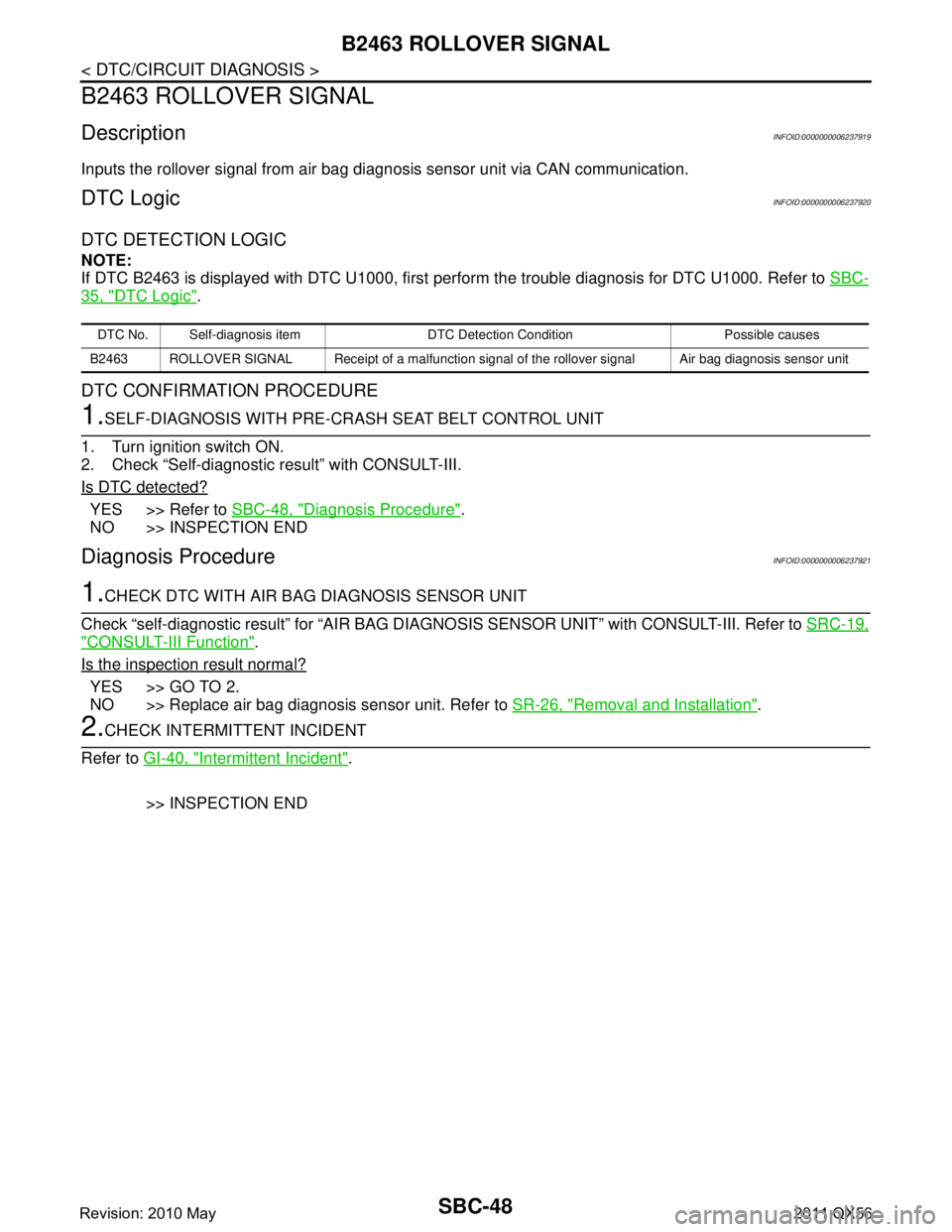
B2463 ROLLOVER SIGNAL
B2463 ROLLOVER SIGNAL
DescriptionINFOID:0000000006237919
Inputs the rollover signal from air bag diagnosis sensor unit via CAN communication.
DTC LogicINFOID:0000000006237920
DTC DETECTION LOGIC
NOTE:
If DTC B2463 is displayed with DTC U1000, first perform the trouble diagnosis for DTC U1000. Refer to SBC-
35, "DTC Logic".
DTC CONFIRMATION PROCEDURE
1.SELF-DIAGNOSIS WITH PRE-CRASH SEAT BELT CONTROL UNIT
1. Turn ignition switch ON.
2. Check “Self-diagnostic result” with CONSULT-III.
Is DTC detected?
YES >> Refer to SBC-48, "Diagnosis Procedure".
NO >> INSPECTION END
Diagnosis ProcedureINFOID:0000000006237921
1.CHECK DTC WITH AIR BAG DIAGNOSIS SENSOR UNIT
Check “self-diagnostic result” for “AIR BAG DIAGNO SIS SENSOR UNIT” with CONSULT-III. Refer to SRC-19,
"CONSULT-III Function".
Is the inspection result normal?
YES >> GO TO 2.
NO >> Replace air bag diagnosis sensor unit. Refer to SR-26, "
Removal and Installation".
2.CHECK INTERMITTENT INCIDENT
Refer to GI-40, "
Intermittent Incident".
>> INSPECTION END
DTC No. Self-diagnosis item DTC De tection Condition Possible causes
B2463 ROLLOVER SIGNAL Receipt of a malfunction signal of the rollover signal Air bag diagnosis sensor unit
Revision: 2010 May2011 QX56
Page 4350 of 5598
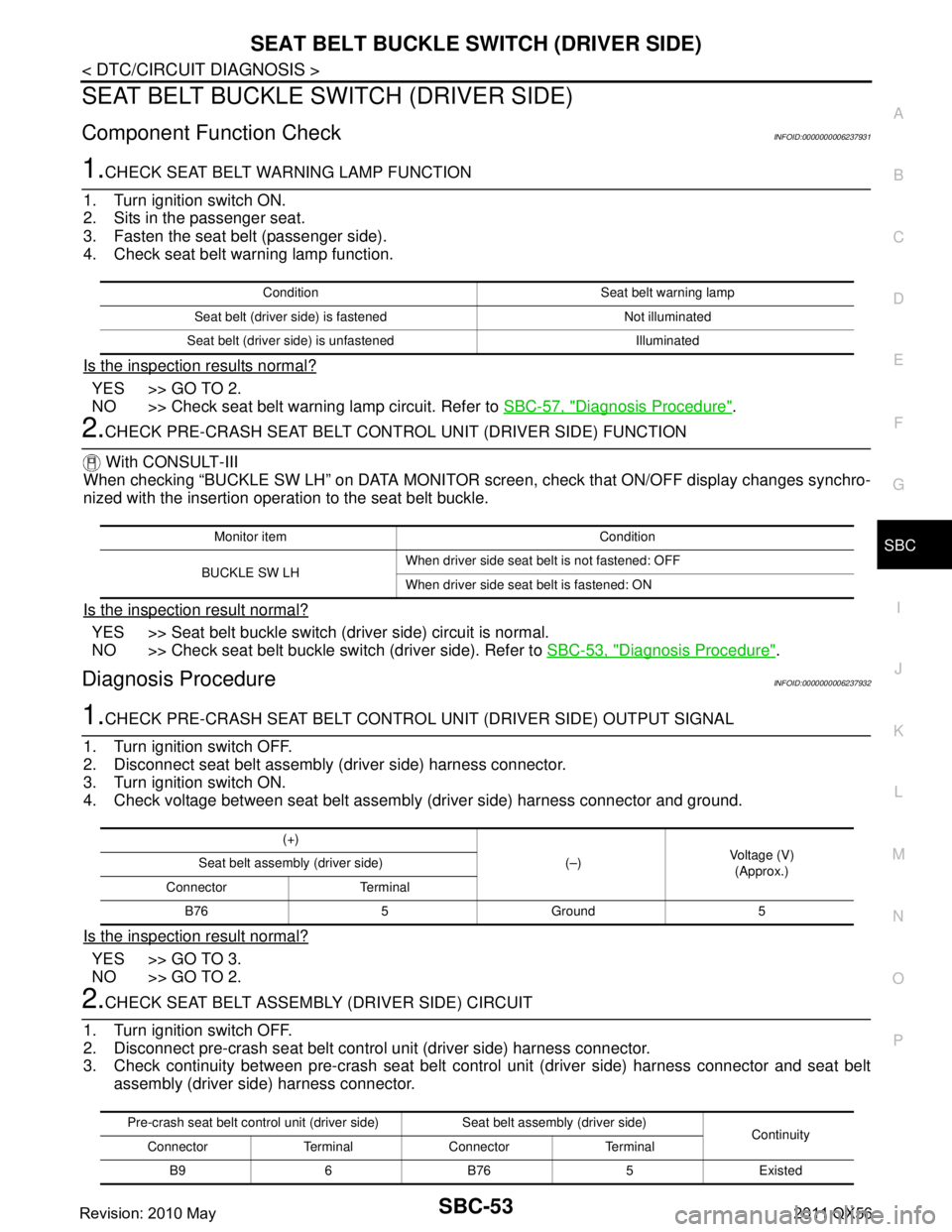
SEAT BELT BUCKLE SWITCH (DRIVER SIDE)
SBC-53
< DTC/CIRCUIT DIAGNOSIS >
C
D E
F
G
I
J
K L
M A
B
SBC
N
O P
SEAT BELT BUCKLE SW ITCH (DRIVER SIDE)
Component Function CheckINFOID:0000000006237931
1.CHECK SEAT BELT WARNING LAMP FUNCTION
1. Turn ignition switch ON.
2. Sits in the passenger seat.
3. Fasten the seat belt (passenger side).
4. Check seat belt warning lamp function.
Is the inspection results normal?
YES >> GO TO 2.
NO >> Check seat belt warning lamp circuit. Refer to SBC-57, "
Diagnosis Procedure".
2.CHECK PRE-CRASH SEAT BELT CONTROL UNIT (DRIVER SIDE) FUNCTION
With CONSULT-III
When checking “BUCKLE SW LH” on DATA MONITOR scr een, check that ON/OFF display changes synchro-
nized with the insertion operat ion to the seat belt buckle.
Is the inspection result normal?
YES >> Seat belt buckle switch (driver side) circuit is normal.
NO >> Check seat belt buckle switch (driver side). Refer to SBC-53, "
Diagnosis Procedure".
Diagnosis ProcedureINFOID:0000000006237932
1.CHECK PRE-CRASH SEAT BELT CONTROL UNIT (DRIVER SIDE) OUTPUT SIGNAL
1. Turn ignition switch OFF.
2. Disconnect seat belt assembly (driver side) harness connector.
3. Turn ignition switch ON.
4. Check voltage between seat belt assembly (driver side) harness connector and ground.
Is the inspection result normal?
YES >> GO TO 3.
NO >> GO TO 2.
2.CHECK SEAT BELT ASSEMB LY (DRIVER SIDE) CIRCUIT
1. Turn ignition switch OFF.
2. Disconnect pre-crash seat belt control unit (driver side) harness connector.
3. Check continuity between pre-crash seat belt cont rol unit (driver side) harness connector and seat belt
assembly (driver side) harness connector.
Condition Seat belt warning lamp
Seat belt (driver side) is fastened Not illuminated
Seat belt (driver side) is unfastened Illuminated
Monitor item Condition
BUCKLE SW LH When driver side seat belt is not fastened: OFF
When driver side seat belt is fastened: ON
(+)
(–)Voltage (V)
(Approx.)
Seat belt assembly (driver side)
Connector Terminal B76 5 Ground 5
Pre-crash seat belt control unit (driver side) Seat belt assembly (driver side) Continuity
Connector Terminal Connector Terminal
B9 6 B76 5 Existed
Revision: 2010 May2011 QX56
Page 4352 of 5598
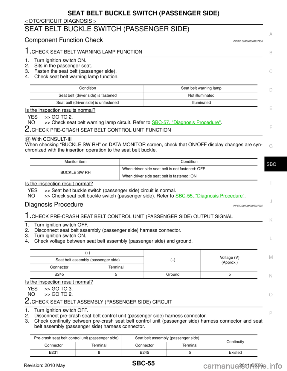
SEAT BELT BUCKLE SWITCH (PASSENGER SIDE)SBC-55
< DTC/CIRCUIT DIAGNOSIS >
C
DE
F
G
I
J
K L
M A
B
SBC
N
O P
SEAT BELT BUCKLE SW ITCH (PASSENGER SIDE)
Component Function CheckINFOID:0000000006237934
1.CHECK SEAT BELT WARNING LAMP FUNCTION
1. Turn ignition switch ON.
2. Sits in the passenger seat.
3. Fasten the seat belt (passenger side).
4. Check seat belt warning lamp function.
Is the inspection results normal?
YES >> GO TO 2.
NO >> Check seat belt warning lamp circuit. Refer to SBC-57, "
Diagnosis Procedure".
2.CHECK PRE-CRASH SEAT BELT CONTROL UNIT FUNCTION
With CONSULT-III
When checking “BUCKLE SW RH” on DATA MONITOR scr een, check that ON/OFF display changes are syn-
chronized with the insertion operation to the seat belt buckle.
Is the inspection result normal?
YES >> Seat belt buckle switch (passenger side) circuit is normal.
NO >> Check seat belt buckle switch (passenger side). Refer to SBC-55, "
Diagnosis Procedure".
Diagnosis ProcedureINFOID:0000000006237935
1.CHECK PRE-CRASH SEAT BELT CONTROL UNIT (PASSENGER SIDE) OUTPUT SIGNAL
1. Turn ignition switch OFF.
2. Disconnect seat belt assembly (passenger side) harness connector.
3. Turn ignition switch ON.
4. Check voltage between seat belt assembly (passenger side) and ground.
Is the inspection result normal?
YES >> GO TO 3.
NO >> GO TO 2.
2.CHECK SEAT BELT ASSEMBLY (PASSENGER SIDE) CIRCUIT
1. Turn ignition switch OFF.
2. Disconnect pre-crash seat belt contro l unit (passenger side) harness connector.
3. Check continuity between pre-crash seat belt c ontrol unit (passenger side) harness connector and seat
belt assembly (passenger side) harness connector.
Condition Seat belt warning lamp
Seat belt (driver side) is fastened Not illuminated
Seat belt (driver side) is unfastened Illuminated
Monitor item Condition
BUCKLE SW RH When driver side seat belt is not fastened: OFF
When driver side seat belt is fastened: ON
(+)
(–)Voltage (V)
(Approx.)
Seat belt assembly (passenger side)
Connector Terminal B245 5 Ground 5
Pre-crash seat belt control unit (passenger side) Seat belt assembly (passenger side) Continuity
Connector Terminal Connector Terminal
B2316B2455Existed
Revision: 2010 May2011 QX56
Page 4411 of 5598
![INFINITI QX56 2011 Factory Service Manual
COMPONENT PARTSSCS-51
< SYSTEM DESCRIPTION > [AIR LEVELIZER CONTROL SYSTEM]
C
D
F
G H
I
J
K L
M A
B
SCS
N
O P
Air Levelizer Control ModuleINFOID:0000000006256042
Operates ON/OFF of air compressor ( INFINITI QX56 2011 Factory Service Manual
COMPONENT PARTSSCS-51
< SYSTEM DESCRIPTION > [AIR LEVELIZER CONTROL SYSTEM]
C
D
F
G H
I
J
K L
M A
B
SCS
N
O P
Air Levelizer Control ModuleINFOID:0000000006256042
Operates ON/OFF of air compressor (](/manual-img/42/57033/w960_57033-4410.png)
COMPONENT PARTSSCS-51
< SYSTEM DESCRIPTION > [AIR LEVELIZER CONTROL SYSTEM]
C
D
F
G H
I
J
K L
M A
B
SCS
N
O P
Air Levelizer Control ModuleINFOID:0000000006256042
Operates ON/OFF of air compressor (exhaust solenoid) , according to signal from vehicle height sensor.
Transmits CK SUSP indicator lamp signal to the combination meter via CAN communication, when setting of standard vehicle height is incomplete.
If malfunction is detected, the syste m enters fail-safe mode. Refer to SCS-59, "
Fail-safe".
Vehicle Height SensorINFOID:0000000006256043
Measures vehicle height of vehicle rear and transmits th is information to air levelizer control module according
to electric signal.
Air CompressorINFOID:0000000006256044
Operates according to signal from air levelizer control module via air compressor relay, and charges air in air
chamber of rear shock absorber.
EXHAUST SOLENOID
Operates according to signal from air levelizer control module, and discharges air in air chamber of rear shock
absorber.
Air Compressor RelayINFOID:0000000006256045
Turns ON according to signal from air levelizer control module, and operates air compressor.
CK SUSP Indicator LampINFOID:0000000006256046
Turns ON for 2 seconds when ignition switch is turned ON, for the purpose of bulb check.
Turns ON when setting of standard vehicle height is incomplete.
NOTE:
Does not turn ON when the system is malfunctioning.
Air compressor relay SCS-51, "Air Compressor Relay"
CK SUSP indicator lampSCS-51, "CK SUSP Indicator Lamp"
Component parts Reference
Revision: 2010 May2011 QX56