2011 INFINITI QX56 oil pressure
[x] Cancel search: oil pressurePage 2548 of 5598
![INFINITI QX56 2011 Factory Service Manual
EC-524
< SYMPTOM DIAGNOSIS >[VK56VD]
ENGINE CONTROL SYSTEM SYMPTOMS
SYMPTOM DIAGNOSIS
ENGINE CONTROL SYSTEM SYMPTOMS
Symptom TableINFOID:0000000006218028
SYSTEM — BASIC ENGINE CONTROL SYSTEM
SYMPTO INFINITI QX56 2011 Factory Service Manual
EC-524
< SYMPTOM DIAGNOSIS >[VK56VD]
ENGINE CONTROL SYSTEM SYMPTOMS
SYMPTOM DIAGNOSIS
ENGINE CONTROL SYSTEM SYMPTOMS
Symptom TableINFOID:0000000006218028
SYSTEM — BASIC ENGINE CONTROL SYSTEM
SYMPTO](/manual-img/42/57033/w960_57033-2547.png)
EC-524
< SYMPTOM DIAGNOSIS >[VK56VD]
ENGINE CONTROL SYSTEM SYMPTOMS
SYMPTOM DIAGNOSIS
ENGINE CONTROL SYSTEM SYMPTOMS
Symptom TableINFOID:0000000006218028
SYSTEM — BASIC ENGINE CONTROL SYSTEM
SYMPTOM
Reference
page
HARD/NO START/RESTART (EXCP. HA)
ENGINE STALL
HESITATION/SURGING/FLAT SPOT
SPARK KNOCK/DETONATION
LACK OF POWER/POOR ACCELERATION
HIGH IDLE/LOW IDLE
ROUGH IDLE/HUNTING
IDLING VIBRATION
SLOW/NO RETURN TO IDLE
OVERHEATS/WATER TEMPERATURE HIGH
EXCESSIVE FUEL CONSUMPTION
EXCESSIVE OIL CONSUMPTION
BATTERY DEAD (UNDER CHARGE)
Warranty symptom code AA AB AC AD AE AF AG AH AJ AK AL AM HA
Fuel Low pressure fuel pump circuit 11232 22 3 2 EC-512
Low fuel pressure sensor circuit 4 4EC-483
Fuel pressure regulator system 334444444 4EC-198
Fuel injector circuit 11232 22 2EC-498
Evaporative emission system 334444444 4EC-532
FRP sensor circuit 11222 22 2EC-276EC-279
High pressure fuel pump circuit 4 3
EC-501
Air Positive crankcase ventilation sys-
tem 334444444 41
EC-534
Incorrect idle speed adjustment 1 1 1 1 1 EC-139
Electric throttle control actuator 112332222 2 2EC-460EC-466
IgnitionIncorrect ignition timing adjustment33111 11 1
EC-139
Ignition circuit 11222 22 2EC-506
Main power supply and ground circuit 22333 33 23 EC-168
Revision: 2010 May2011 QX56
Page 2549 of 5598
![INFINITI QX56 2011 Factory Service Manual
ENGINE CONTROL SYSTEM SYMPTOMSEC-525
< SYMPTOM DIAGNOSIS > [VK56VD]
C
D
E
F
G H
I
J
K L
M A
EC
NP
O
Mass air flow sensor circuit
1
12 2
222 2 EC-201
Engine coolant temperature sensor circuit
333
EC-2 INFINITI QX56 2011 Factory Service Manual
ENGINE CONTROL SYSTEM SYMPTOMSEC-525
< SYMPTOM DIAGNOSIS > [VK56VD]
C
D
E
F
G H
I
J
K L
M A
EC
NP
O
Mass air flow sensor circuit
1
12 2
222 2 EC-201
Engine coolant temperature sensor circuit
333
EC-2](/manual-img/42/57033/w960_57033-2548.png)
ENGINE CONTROL SYSTEM SYMPTOMSEC-525
< SYMPTOM DIAGNOSIS > [VK56VD]
C
D
E
F
G H
I
J
K L
M A
EC
NP
O
Mass air flow sensor circuit
1
12 2
222 2 EC-201
Engine coolant temperature sensor circuit
333
EC-217
Air fuel ratio (A/F) sensor 1 circuit EC-181
EC-228
EC-232
EC-235
EC-238
Throttle position sensor circuit
22EC-219
EC-288
EC-406
EC-407
EC-475
Accelerator pedal position sensor circuit 3 2 1
EC-468EC-471
EC-478
Knock sensor circuit 2 3
EC-297
Engine oil temperature sensor 4 2 3EC-285
Crankshaft position sensor circuit 2 2EC-299
Camshaft position sensor circuit 3 2EC-303
Vehicle speed signal circuit 2 3 3 3EC-356
Power steering pressure sensor circuit 2 3 3EC-371
ECM 22333333333EC-376EC-378
EC-380
Intake valve timing control solenoid valve cir-
cuit
32 13223 3
EC-193
VVEL control module 3 4 4 3 EC-451EC-452
VVEL actuator motor 3 4 4 3
EC-390
VVEL actuator motor relay 3 4 4 3EC-393
VVEL control shaft position sensor 3 4 4 3EC-387
PNP signal circuit 3 3 3 3 3EC-383
Refrigerant pressure sensor circuit 2 3 3 4EC-520
Electrical load signal circuit 3EC-493
Air conditioner circuit 223333333 3 2HAC-60
ABS actuator and electric unit (control unit) 4BRC-60
SYMPTOM
Reference
page
HARD/NO START/RESTART (EXCP. HA)
ENGINE STALL
HESITATION/SURGING/FLAT SPOT
SPARK KNOCK/DETONATION
LACK OF POWER/POOR ACCELERATION
HIGH IDLE/LOW IDLE
ROUGH IDLE/HUNTING
IDLING VIBRATION
SLOW/NO RETURN TO IDLE
OVERHEATS/WATER TEMPERATURE HIGH
EXCESSIVE FUEL CONSUMPTION
EXCESSIVE OIL CONSUMPTION
BATTERY DEAD (UNDER CHARGE)
Warranty symptom code AA AB AC AD AE AF AG AH AJ AK AL AM HA
Revision: 2010 May2011 QX56
Page 2550 of 5598
![INFINITI QX56 2011 Factory Service Manual
EC-526
< SYMPTOM DIAGNOSIS >[VK56VD]
ENGINE CONTROL SYSTEM SYMPTOMS
1 - 6: The numbers refer to the order of inspection.
(continued on next page)
SYSTEM — ENGINE MECHANICAL & OTHER
Manifold absolut INFINITI QX56 2011 Factory Service Manual
EC-526
< SYMPTOM DIAGNOSIS >[VK56VD]
ENGINE CONTROL SYSTEM SYMPTOMS
1 - 6: The numbers refer to the order of inspection.
(continued on next page)
SYSTEM — ENGINE MECHANICAL & OTHER
Manifold absolut](/manual-img/42/57033/w960_57033-2549.png)
EC-526
< SYMPTOM DIAGNOSIS >[VK56VD]
ENGINE CONTROL SYSTEM SYMPTOMS
1 - 6: The numbers refer to the order of inspection.
(continued on next page)
SYSTEM — ENGINE MECHANICAL & OTHER
Manifold absolute pressure sensor circuit 3
EC-210
Battery current sensor 4 5 5 3EC-412EC-420
EC-424
Heated oxygen sensor 2 6 6 6 6 5EC-243EC-249
EC-257
SYMPTOM
Reference
page
HARD/NO START/RESTART (EXCP. HA)
ENGINE STALL
HESITATION/SURGING/FLAT SPOT
SPARK KNOCK/DETONATION
LACK OF POWER/POOR ACCELERATION
HIGH IDLE/LOW IDLE
ROUGH IDLE/HUNTING
IDLING VIBRATION
SLOW/NO RETURN TO IDLE
OVERHEATS/WATER TEMPERATURE HIGH
EXCESSIVE FUEL CONSUMPTION
EXCESSIVE OIL CONSUMPTION
BATTERY DEAD (UNDER CHARGE)
Warranty symptom code AA AB AC AD AE AF AG AH AJ AK AL AM HA
Fuel Fuel tank 5
5 FL-4
Fuel piping 555 55 5
FL-4
Vapor lock —
Valve deposit 5 555 55 5 —
Poor fuel (Heavy weight gasoline,
Low octane) —
Revision: 2010 May2011 QX56
Page 2563 of 5598

EM-1
ENGINE
C
DE
F
G H
I
J
K L
M
SECTION EM
A
EM
N
O P
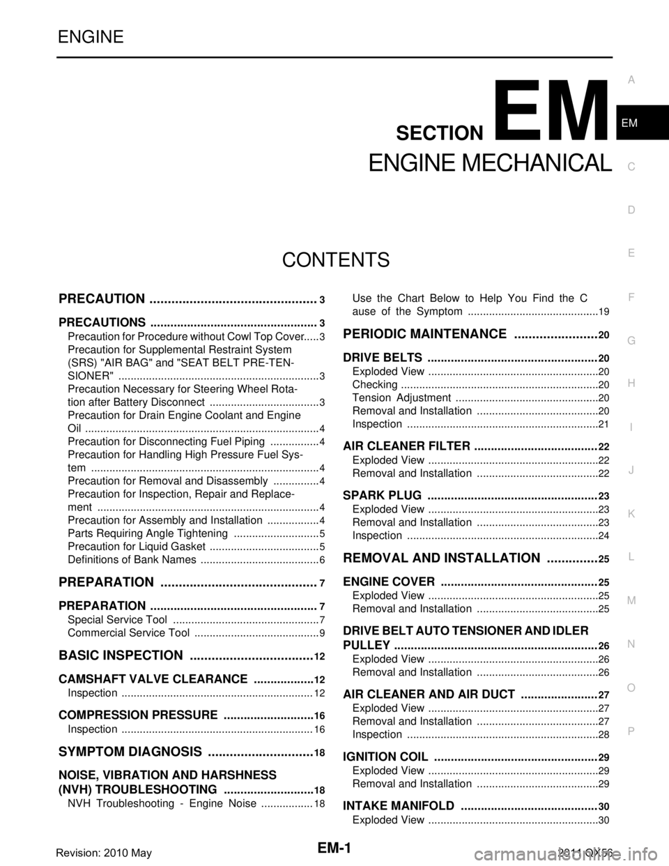
CONTENTS
ENGINE MECHANICAL
PRECAUTION ................ ...............................3
PRECAUTIONS .............................................. .....3
Precaution for Procedure without Cowl Top Cover ......3
Precaution for Supplemental Restraint System
(SRS) "AIR BAG" and "SEAT BELT PRE-TEN-
SIONER" ...................................................................
3
Precaution Necessary for Steering Wheel Rota-
tion after Battery Disconnect .....................................
3
Precaution for Drain Engine Coolant and Engine
Oil ..............................................................................
4
Precaution for Disconnecting Fuel Piping .................4
Precaution for Handling High Pressure Fuel Sys-
tem ............................................................................
4
Precaution for Removal and Disassembly ................4
Precaution for Inspection, Repair and Replace-
ment ..........................................................................
4
Precaution for Assembly and Installation ..................4
Parts Requiring Angle Tightening .............................5
Precaution for Liquid Gasket .....................................5
Definitions of Bank Names ........................................6
PREPARATION ............................................7
PREPARATION .............................................. .....7
Special Service Tool ........................................... ......7
Commercial Service Tool ..........................................9
BASIC INSPECTION ...................................12
CAMSHAFT VALVE CLEARANCE ............... ....12
Inspection ............................................................ ....12
COMPRESSION PRESSURE ............................16
Inspection ............................................................ ....16
SYMPTOM DIAGNOSIS ..............................18
NOISE, VIBRATION AND HARSHNESS
(NVH) TROUBLESHOOTING ........................ ....
18
NVH Troubleshooting - Engine Noise .............. ....18
Use the Chart Below to Help You Find the C
ause of the Symptom ........................................ ....
19
PERIODIC MAINTENANCE ........................20
DRIVE BELTS ...................................................20
Exploded View ..................................................... ....20
Checking ..................................................................20
Tension Adjustment ................................................20
Removal and Installation .........................................20
Inspection ................................................................21
AIR CLEANER FILTER .....................................22
Exploded View .........................................................22
Removal and Installation .........................................22
SPARK PLUG ...................................................23
Exploded View .........................................................23
Removal and Installation .........................................23
Inspection ................................................................24
REMOVAL AND INSTALLATION ...............25
ENGINE COVER ...............................................25
Exploded View ..................................................... ....25
Removal and Installation .........................................25
DRIVE BELT AUTO TENSIONER AND IDLER
PULLEY .............................................................
26
Exploded View .........................................................26
Removal and Installation .........................................26
AIR CLEANER AND AIR DUCT .......................27
Exploded View .........................................................27
Removal and Installation .........................................27
Inspection ................................................................28
IGNITION COIL .................................................29
Exploded View .........................................................29
Removal and Installation .........................................29
INTAKE MANIFOLD .........................................30
Exploded View .........................................................30
Revision: 2010 May2011 QX56
Page 2564 of 5598

EM-2
Removal and Installation ........................................30
ROCKER COVER ..............................................33
Exploded View ..................................................... ...33
Removal and Installation ........................................33
VVEL ACTUATOR ASSEMBLY ........................36
Exploded View ..................................................... ...36
Removal and Installation ........................................36
Inspection ...............................................................39
EXHAUST MANIFOLD AND THREE WAY
CATALYST ........................................................
40
Exploded View ..................................................... ...40
Removal and Installation ........................................40
Inspection ...............................................................42
HIGH PRESSURE FUEL PUMP AND FUEL
HOSE .................................................................
43
Exploded View ..................................................... ...43
Removal and Installation ........................................43
Inspection ...............................................................46
FUEL INJECTOR AND FUEL TUBE .................48
Exploded View ..................................................... ...48
Removal and Installation ........................................49
Inspection ...............................................................53
OIL PAN (LOWER) AND OIL STRAINER .........54
Exploded View ..................................................... ...54
Removal and Installation ........................................55
Inspection ...............................................................56
OIL PAN (UPPER) .......................................... ...57
Exploded View ..................................................... ...57
Removal and Installation ........................................58
Inspection ...............................................................60
TIMING CHAIN ............................................... ...61
Exploded View ..................................................... ...61
Removal and Installation ........................................62
Inspection ...............................................................72
CAMSHAFT .......................................................74
Exploded View ..................................................... ...74
Removal and Installation ........................................75
Inspection ...............................................................77
CYLINDER HEAD ..............................................86
Exploded View ..................................................... ...86
Removal and Installation ........................................87
Disassembly and Assembly ....................................89
Inspection ............................................................. ...92
OIL SEAL ...........................................................96
FRONT OIL SEAL .................................................. ...96
FRONT OIL SEAL : Removal and Installation ........96
REAR OIL SEAL .................................................... ...96
REAR OIL SEAL : Removal and Installation ...........97
UNIT REMOVAL AND INSTALLATION ....98
ENGINE ASSEMBL Y ..................................... ...98
Exploded View ..................................................... ...98
Removal and Installation .........................................99
Inspection ..............................................................102
UNIT DISASSEMBLY AND ASSEMBLY ..103
ENGINE STAND SETTING ..............................103
Setting .................................................................. .103
ENGINE UNIT ...................................................105
Disassembly ......................................................... .105
Assembly ..............................................................105
CYLINDER BLOCK ..........................................106
Exploded View ..................................................... .106
Disassembly and Assembly ..................................107
Inspection ..............................................................115
HOW TO SELECT PISTON AND BEARING ...125
Description ........................................................... .125
Piston ....................................................................125
Connecting Rod Bearing .....................................126
Main Bearing ........................................................128
SERVICE DATA AND SPECIFICATIONS
(SDS) ........ .................................................
132
SERVICE DATA AND SPECIFICATIONS
(SDS) .............................................................. ..
132
General Specification .......................................... .132
Drive Belts .............................................................132
Spark Plug ............................................................132
Exhaust Manifold ..................................................133
Camshaft ...............................................................133
Cylinder Head ......................................................135
Cylinder Block ......................................................137
Main Bearing ........................................................141
Connecting Rod Bearing .....................................142
Revision: 2010 May2011 QX56
Page 2566 of 5598

EM-4
< PRECAUTION >
PRECAUTIONS
If turning the steering wheel is required with the battery disconnected or discharged, follow the operation pro-
cedure below before starting the repair operation.
OPERATION PROCEDURE
1. Connect both battery cables.
NOTE:
Supply power using jumper cables if battery is discharged.
2. Turn the push-button ignition switch to ACC position. (At this time, the steering lock will be released.)
3. Disconnect both battery cables. The steering lock wi ll remain released with both battery cables discon-
nected and the steering wheel can be turned.
4. Perform the necessary repair operation.
5. When the repair work is completed, re-connect bot h battery cables. With the brake pedal released, turn
the push-button ignition switch from ACC position to ON position, then to LOCK position. (The steering
wheel will lock when the push-button igniti on switch is turned to LOCK position.)
6. Perform self-diagnosis check of all control units using CONSULT-III.
Precaution for Drain Engine Coolant and Engine OilINFOID:0000000006289509
Drain engine coolant and engine oil when engine is cooled.
Precaution for Disconnecting Fuel PipingINFOID:0000000006289510
Before starting work, check no fire or sp ark producing items are in the work area.
Release fuel pressure before disconnecting and disassembly.
After disconnecting pipes, plug openings to stop fuel leakage.
Precaution for Handling High Pressure Fuel SystemINFOID:0000000006289511
High pressure fuel system components are betw een high pressure fuel pump and fuel injector.
Always release fuel pressure and never start the engine when performing removal and installation.
When removing or installing parts without releasing fuel pressure, fuel may be splashed and, if fuel contacts
skin or eyes, it may cause inflammation.
Precaution for Removal and DisassemblyINFOID:0000000006289512
When instructed to use SST, use specified tools. Always be careful to work safely, avoid forceful or unin-
structed operations.
Exercise maximum care to avoid damage to mating or sliding surfaces.
Cover openings of engine system with tape or the equival ent, if necessary, to seal out foreign materials.
Mark and arrange disassembly parts in an organi zed way for easy troubleshooting and assembly.
When loosening nuts and bolts, as a basic rule, star t with the one furthest outside, then the one diagonally
opposite, and so on. If the order of loosening is specified, do exactly as specified. Power tools may be used
where noted in the step.
Precaution for Inspection, Repair and ReplacementINFOID:0000000006289513
Before repairing or replacing, thoroughly inspect parts. Inspect new replacement parts in the same way, and
replace if necessary.
Precaution for Assembly and InstallationINFOID:0000000006289514
Use torque wrench to tighten bolts or nuts to specification.
When tightening nuts and bolts, as a basic rule, equally tighten in several different steps starting with the
ones in center, then ones on inside and outside diagonally in this order. If the order of tightening is specified,
do exactly as specified.
Replace with new gasket, packing, oil seal or O-ring.
Thoroughly wash, clean, and air-blow each part. Carefully check engine oil or engine coolant passages for
any restriction and blockage.
Dowel pins are used for several parts alignment. When replacing and reassembling parts with dowel pins,
check that dowel pins are installed in the original position.
Revision: 2010 May2011 QX56
Page 2578 of 5598

EM-16
< BASIC INSPECTION >
COMPRESSION PRESSURE
COMPRESSION PRESSURE
InspectionINFOID:0000000006289521
1. Warm up engine thoroughly. Then, stop it.
2. Release fuel pressure. Refer to EC-153, "
Work Procedure".
CAUTION:
If CONSULT-III is not used to release fuel pr essure leave the fuel pump fuse disconnected until
step 7.
3. Remove fuel pump fuse in IPDM E/R. NOTE:
For the fuse number, refer to EC-114, "
Wiring Diagram".
For the fuse arrangement, refer to PG-143, "
Fuse, Connector and Terminal Arrangement".
4. Remove engine cover. Refer to EM-25, "
Exploded View".
5. Remove ignition coil and spark plug from each cylinder. Refer to EM-29, "
Exploded View".
6. Connect engine tachometer (not required in use of CONSULT-III).
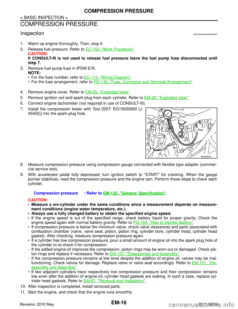
7. Install the compression tester with Tool [SST: EG15050500 (J- 45402)] into the spark plug hole.
8. Measure compression pressure using compressi on gauge connected with flexible type adapter (commer-
cial service tool).
9. With accelerator pedal fully depressed, turn ignition switch to “START” for cranking. When the gauge pointer stabilizes, read the compression pressure and the engine rpm. Perform these steps to check each
cylinder.
CAUTION:
Measure a six-cylinder under the same conditio ns since a measurement depends on measure-
ment conditions (engine water temperature, etc.).
Always use a fully changed battery to obtain the specified engine speed.
If the engine speed is out of the specified range, c heck battery liquid for proper gravity. Check the
engine speed again with normal battery gravity. Refer to PG-159, "
How to Handle Battery".
If compression pressure is below the minimum value, check valve clearances and parts associated with combustion chamber (valve, valve seat, piston, pi ston ring, cylinder bore, cylinder head, cylinder head
gasket). After checking, measure compression pressure again.
If a cylinder has low compression pressure, pour a small amount of engine oil into the spark plug hole of the cylinder to re-check it for compression.
- If the added engine oil improves the compression, pi ston rings may be worn out or damaged. Check pis-
ton rings and replace if necessary. Refer to EM-107, "
Disassembly and Assembly".
- If the compression pressure remains at low level despite the addition of engine oil, valves may be mal- functioning. Check valves for damage. Replace valve or valve seat accordingly. Refer to EM-107, "
Dis-
assembly and Assembly".
If two adjacent cylinders have respectively low co mpression pressure and their compression remains
low even after the addition of engine oil, cylinder head gaskets are leaking. In such a case, replace cyl-
inder head gaskets. Refer to EM-87, "
Removal and Installation".
10. After inspection is completed, install removed parts.
11. Start the engine, and check that the engine runs smoothly.
WBIA0605E
Compression pressure : Refer to EM-132, "GeneralSpecification".
Revision: 2010 May2011 QX56
Page 2586 of 5598

EM-24
< PERIODIC MAINTENANCE >
SPARK PLUG
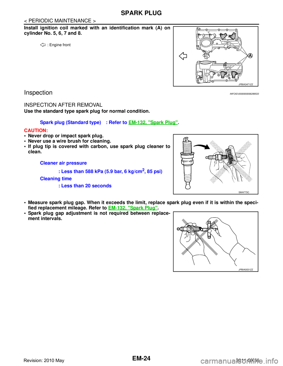
Install ignition coil marked with an identification mark (A) on
cylinder No. 5, 6, 7 and 8.
InspectionINFOID:0000000006289533
INSPECTION AFTER REMOVAL
Use the standard type spark plug for normal condition.
CAUTION:
Never drop or impact spark plug.
Never use a wire brush for cleaning.
If plug tip is covered with carbon, use spark plug cleaner to clean.
Measure spark plug gap. When it exceeds the limit, replace spark plug even if it is within the speci-
fied replacement mileage. Refer to EM-132, "
Spark Plug".
Spark plug gap adjustment is not required between replace-
ment intervals.
: Engine front
JPBIA3471ZZ
Spark plug (Standard type) : Refer to EM-132, "Spark Plug".
Cleaner air pressure : Less than 588 kPa (5.9 bar, 6 kg/cm
2, 85 psi)
Cleaning time : Less than 20 seconds
SMA773C
JPBIA0031ZZ
Revision: 2010 May2011 QX56