2011 INFINITI QX56 oil pressure
[x] Cancel search: oil pressurePage 2635 of 5598
TIMING CHAINEM-73
< REMOVAL AND INSTALLATION >
C
DE
F
G H
I
J
K L
M A
EM
NP
O
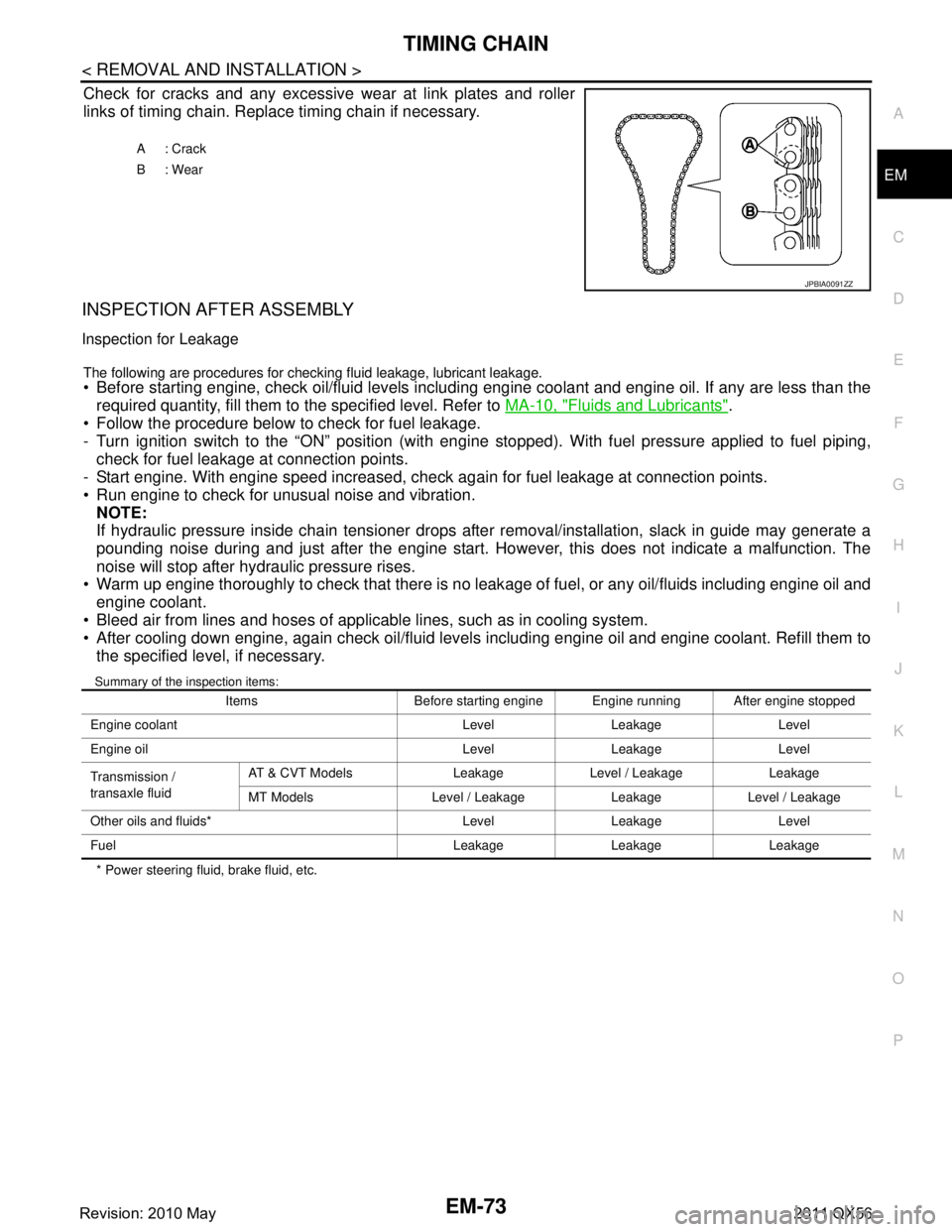
Check for cracks and any excessive
wear at link plates and roller
links of timing chain. Replace timing chain if necessary.
INSPECTION AFTER ASSEMBLY
Inspection for Leakage
The following are procedures for chec king fluid leakage, lubricant leakage. Before starting engine, check oil/fluid levels including engine coolant and engine oil. If any are less than the
required quantity, fill them to the specified level. Refer to MA-10, "
Fluids and Lubricants".
Follow the procedure below to check for fuel leakage.
- Turn ignition switch to the “ON” position (with engi ne stopped). With fuel pressure applied to fuel piping,
check for fuel leakage at connection points.
- Start engine. With engine speed increased, check again for fuel leakage at connection points.
Run engine to check for unusual noise and vibration.
NOTE:
If hydraulic pressure inside chain tensioner drops after removal/installation, slack in guide may generate a
pounding noise during and just after the engine start. However, this does not indicate a malfunction. The
noise will stop after hydraulic pressure rises.
Warm up engine thoroughly to check that there is no leak age of fuel, or any oil/fluids including engine oil and
engine coolant.
Bleed air from lines and hoses of applicable lines, such as in cooling system.
After cooling down engine, again check oil/fluid levels including engine oil and engine coolant. Refill them to the specified level, if necessary.
Summary of the inspection items:
* Power steering fluid, brake fluid, etc. A: Crack
B: Wear
JPBIA0091ZZ
Items Before starting engine Engine running After engine stopped
Engine coolant Level Leakage Level
Engine oil Level Leakage Level
Transmission /
transaxle fluid AT & CVT Models Leakage Level / Leakage Leakage
MT Models Level / Leakage Leakage Level / Leakage
Other oils and fluids* Level Leakage Level
Fuel Leakage Leakage Leakage
Revision: 2010 May2011 QX56
Page 2646 of 5598
EM-84
< REMOVAL AND INSTALLATION >
CAMSHAFT
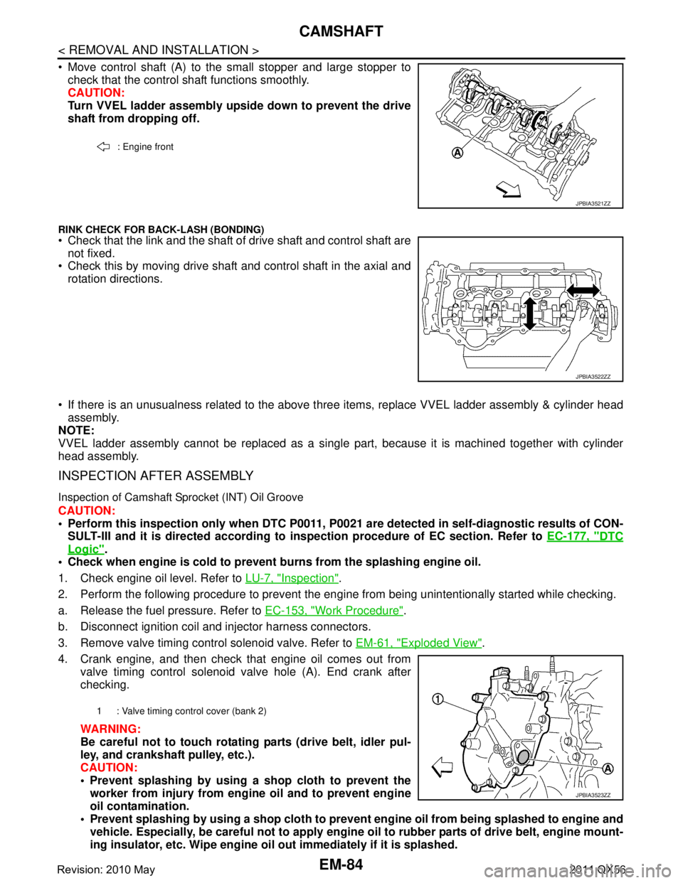
Move control shaft (A) to the small stopper and large stopper tocheck that the control shaft functions smoothly.
CAUTION:
Turn VVEL ladder assembly upside down to prevent the drive
shaft from dropping off.
RINK CHECK FOR BACK-LASH (BONDING) Check that the link and the shaft of drive shaft and control shaft are
not fixed.
Check this by moving drive shaft and control shaft in the axial and
rotation directions.
If there is an unusualness related to the above three items, replace VVEL ladder assembly & cylinder head
assembly.
NOTE:
VVEL ladder assembly cannot be replaced as a singl e part, because it is machined together with cylinder
head assembly.
INSPECTION AFTER ASSEMBLY
Inspection of Camshaft Sprocket (INT) Oil Groove
CAUTION:
Perform this inspection only when DTC P0011, P 0021 are detected in self-diagnostic results of CON-
SULT-III and it is directed according to inspection procedure of EC section. Refer to EC-177, "
DTC
Logic".
Check when engine is cold to prevent burns from the splashing engine oil.
1. Check engine oil level. Refer to LU-7, "
Inspection".
2. Perform the following procedure to prevent the engine from being unintentionally started while checking.
a. Release the fuel pressure. Refer to EC-153, "
Work Procedure".
b. Disconnect ignition coil and injector harness connectors.
3. Remove valve timing control solenoid valve. Refer to EM-61, "
Exploded View".
4. Crank engine, and then check that engine oil comes out from valve timing control solenoid valve hole (A). End crank after
checking.
WARNING:
Be careful not to touch rotati ng parts (drive belt, idler pul-
ley, and crankshaft pulley, etc.).
CAUTION:
Prevent splashing by using a shop cloth to prevent the worker from injury from en gine oil and to prevent engine
oil contamination.
Prevent splashing by using a shop cloth to prevent engine oil from being splashed to engine and
vehicle. Especially, be careful not to apply engine oil to rubber parts of drive belt, engine mount-
ing insulator, etc. Wipe engine oil out immediately if it is splashed.
: Engine front
JPBIA3521ZZ
JPBIA3522ZZ
1 : Valve timing control cover (bank 2)
JPBIA3523ZZ
Revision: 2010 May2011 QX56
Page 2647 of 5598
CAMSHAFTEM-85
< REMOVAL AND INSTALLATION >
C
DE
F
G H
I
J
K L
M A
EM
NP
O
5. Perform the following inspection if engine oil does not
come out from valve timing control solenoid valve
oil hole of the valve timing control cover.
Remove oil filter, and then clean it. Refer to EM-61, "
Exploded View".
Clean oil groove between oil strainer and valve timing control solenoid valve. Refer to LU-5, "
Engine
Lubrication System" and LU-6, "Engine Lubrication System Schematic".
6. Remove components between valve timing control solenoid valve and camshaft sprocket, and then check each oil groove for clogging.
Clean oil groove if necessary. Refer to LU-5, "
Engine Lubrication System" and LU-6, "Engine Lubrica-
tion System Schematic".
7. After inspection, install removed parts in the reverse order.
Inspection for Leakage
The following are procedures for chec king fluid leakage, lubricant leakage.
Before starting engine, check oil/fluid levels including engine coolant and engine oil. If any are less than the
required quantity, fill them to the specified level. Refer to MA-10, "
Fluids and Lubricants".
Follow the procedure below to check for fuel leakage.
- Turn ignition switch to the “ON” position (with engi ne stopped). With fuel pressure applied to fuel piping,
check for fuel leakage at connection points.
- Start engine. With engine speed increased, check again for fuel leakage at connection points.
Run engine to check for unusual noise and vibration. NOTE:
If hydraulic pressure inside chain tensioner drops after removal/installation, slack in guide may generate a
pounding noise during and just after the engine start. However, this does not indicate a malfunction. The
noise will stop after hydraulic pressure rises.
Warm up engine thoroughly to check that there is no leak age of fuel, or any oil/fluids including engine oil and
engine coolant.
Bleed air from lines and hoses of applicable lines, such as in cooling system.
After cooling down engine, again check oil/fluid levels including engine oil and engine coolant. Refill them to
the specified level, if necessary.
Summary of the inspection items:
* Power steering fluid, brake fluid, etc. Items Before starting engine Engine running After engine stopped
Engine coolant Level Leakage Level
Engine oil Level Leakage Level
Transmission /
transaxle fluid AT & CVT Models Leakage Level / Leakage Leakage
MT Models Level / Leakage Leakage Level / Leakage
Other oils and fluids* Level Leakage Level
Fuel Leakage Leakage Leakage
Revision: 2010 May2011 QX56
Page 2652 of 5598
![INFINITI QX56 2011 Factory Service Manual
EM-90
< REMOVAL AND INSTALLATION >
CYLINDER HEAD
b. Drive out valve guide (EXH) with a press [under a 20 kN (2 ton,2.2 US ton, 2.0 lmp ton) pressure] or a hammer and the valve
guide drift (commercial INFINITI QX56 2011 Factory Service Manual
EM-90
< REMOVAL AND INSTALLATION >
CYLINDER HEAD
b. Drive out valve guide (EXH) with a press [under a 20 kN (2 ton,2.2 US ton, 2.0 lmp ton) pressure] or a hammer and the valve
guide drift (commercial](/manual-img/42/57033/w960_57033-2651.png)
EM-90
< REMOVAL AND INSTALLATION >
CYLINDER HEAD
b. Drive out valve guide (EXH) with a press [under a 20 kN (2 ton,2.2 US ton, 2.0 lmp ton) pressure] or a hammer and the valve
guide drift (commercial service tool).
WARNING:
Cylinder head contains heat . When working, wear protec-
tive equipment to avo id getting burned.
ASSEMBLY
1. Install valve guide (EXH), if removed.
Replace with oversized [0.2 mm (0.008 in)] valve guide (EXH).
a. Using the valve guide reamer (commercial service tool) (A), ream cylinder head valve guide (EXH) hole.
b. Heat cylinder head to 110 to 130 °C (230 to 266 °F) by soaking in
heated oil (A).
c. Using the valve guide drift (commercial service tool), press valve guide (EXH) from camshaft side to the dimensions as shown in
the figure.
WARNING:
Cylinder head contains heat . When working, wear protec-
tive equipment to avo id getting burned.
SEM931C
Oversize (service) [0.2 mm (0.008 in)]:
: Refer to EM-135, "
CylinderHead".
JPBIA0185ZZ
JPBIA0184ZZ
Projection (A)
: Refer to EM-135, "
CylinderHead".
JPBIA0186ZZ
Revision: 2010 May2011 QX56
Page 2653 of 5598
CYLINDER HEADEM-91
< REMOVAL AND INSTALLATION >
C
DE
F
G H
I
J
K L
M A
EM
NP
O
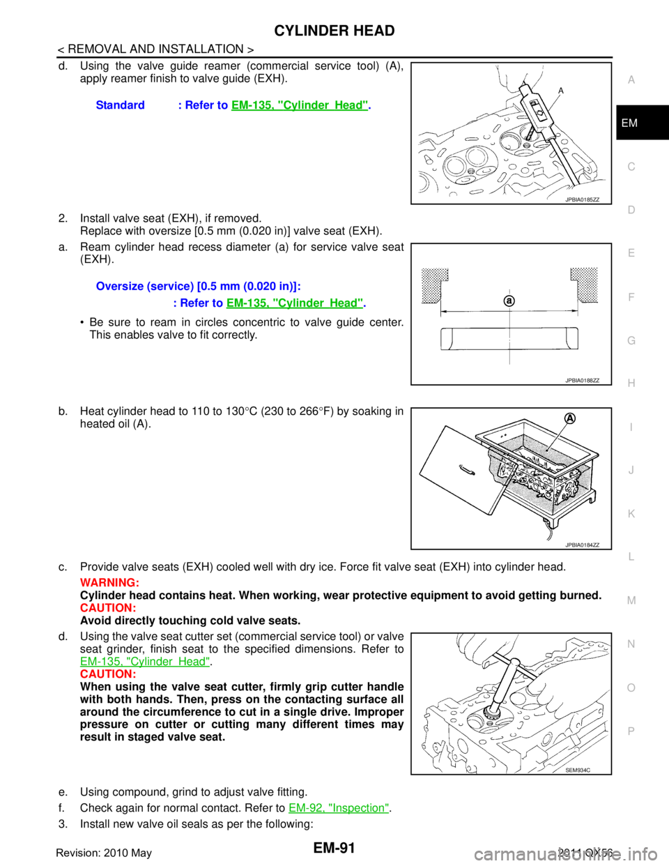
d. Using the valve guide reamer (commercial service tool) (A),
apply reamer finish to valve guide (EXH).
2. Install valve seat (EXH), if removed. Replace with oversize [0.5 mm (0.020 in)] valve seat (EXH).
a. Ream cylinder head recess diameter (a) for service valve seat (EXH).
Be sure to ream in circles concentric to valve guide center.
This enables valve to fit correctly.
b. Heat cylinder head to 110 to 130 °C (230 to 266 °F) by soaking in
heated oil (A).
c. Provide valve seats (EXH) cooled well with dry ice. Force fit valve seat (EXH) into cylinder head. WARNING:
Cylinder head contains heat. When working, w ear protective equipment to avoid getting burned.
CAUTION:
Avoid directly touching cold valve seats.
d. Using the valve seat cutter set (commercial service tool) or valve seat grinder, finish seat to the specified dimensions. Refer to
EM-135, "
CylinderHead".
CAUTION:
When using the valve seat cutt er, firmly grip cutter handle
with both hands. Then, press on the contacting surface all
around the circumference to cu t in a single drive. Improper
pressure on cutter or cutting many different times may
result in staged valve seat.
e. Using compound, grind to adjust valve fitting.
f. Check again for normal contact. Refer to EM-92, "
Inspection".
3. Install new valve oil seals as per the following: Standard : Refer to
EM-135, "
CylinderHead".
JPBIA0185ZZ
Oversize (service) [0.5 mm (0.020 in)]:
: Refer to EM-135, "
CylinderHead".
JPBIA0188ZZ
JPBIA0184ZZ
SEM934C
Revision: 2010 May2011 QX56
Page 2656 of 5598

EM-94
< REMOVAL AND INSTALLATION >
CYLINDER HEAD
Check if the contact area band is continuous all around the circum-ference.
- If not, grind to adjust valve fitting and check again. If the contacting surface still has “NG” conditions even after the re-check, replace
valve seat (EXH). Refer to EM-86, "
Exploded View". (Exhaust
side)
- If not, replace VVEL ladder assembly & cylinder head assembly. Refer to EM-86, "
Exploded View". (Intake side)
NOTE:
Since the valve seat (INT) cannot be replaced by t he piece, VVEL ladder assembly & cylinder head assem-
bly replacement are required.
Valve Spring (with valve spring seat) Squareness
Set a try square (A) along the side of valve spring (with valve
spring seat) and rotate spring. Measure the maximum clearance
between the top of spring and try square.
If it exceeds the limit.
- Replace valve spring (with valve spring seat) (EXH). Refer to EM-
86, "Exploded View". (Exhaust side)
- Replace VVEL ladder assembly & cylinder head assembly. Refer
to EM-86, "
Exploded View". (Intake side)
NOTE:
Since the valve spring (with valve spring seat) (INT) c annot be replaced by the piece, VVEL ladder assembly
& cylinder head assembly replacement are required.
Valve Spring Dimensions and Valve Spring Pressure Load
Check the valve spring (with valve spring seat) pressure at speci- fied spring height.
If the installation load or load with valve open is out of the stan- dard.
- Replace valve spring (with valve spring seat) (EXH). Refer to EM-
86, "Exploded View". (Exhaust side)
- Replace VVEL ladder assembly & cylinder head assembly. Refer to EM-86, "
Exploded View". (Intake side)
NOTE:
Since the valve spring (with valve spring seat) (INT) c annot be replaced by the piece, VVEL ladder assembly
& cylinder head assembly replacement are required.
INSPECTION AFTER ASSEMBLY
Inspection for Leakage
The following are procedures for checking fluid leakage, lubricant leakage.
Before starting engine, check oil/fluid levels includi ng engine coolant and engine oil. If any are less than the
required quantity, fill them to the specified level. Refer to MA-10, "
Fluids and Lubricants".
Follow the procedure below to check for fuel leakage.
- Turn ignition switch to the “ON” position (with engi ne stopped). With fuel pressure applied to fuel piping,
check for fuel leakage at connection points.
- Start engine. With engine speed increased, che ck again for fuel leakage at connection points.
Run engine to check for unusual noise and vibration. NOTE:
A: OK
B: NG
JPBIA0187ZZ
B : Contact
Limit : Refer to EM-135, "CylinderHead".
JPBIA0189ZZ
Standard
: Refer to EM-135, "
CylinderHead".
SEM113
Revision: 2010 May2011 QX56
Page 2657 of 5598
CYLINDER HEADEM-95
< REMOVAL AND INSTALLATION >
C
DE
F
G H
I
J
K L
M A
EM
NP
O
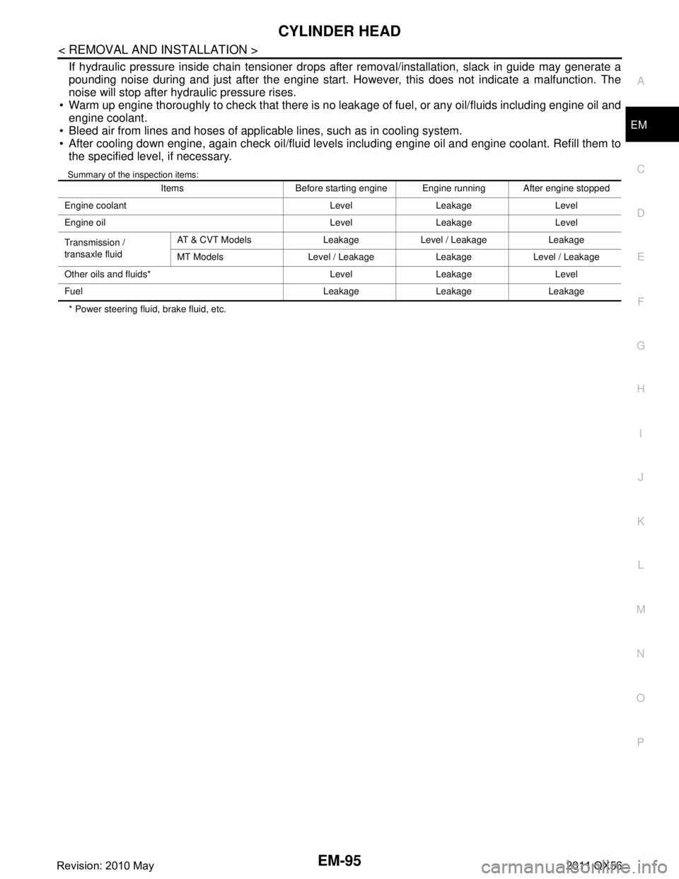
If hydraulic pressure inside chain tensioner drops after removal/installation, slack in guide may generate a
pounding noise during and just after the engine start. However, this does not indicate a malfunction. The
noise will stop after hydraulic pressure rises.
Warm up engine thoroughly to check that there is no leak age of fuel, or any oil/fluids including engine oil and
engine coolant.
Bleed air from lines and hoses of applicable lines, such as in cooling system.
After cooling down engine, again check oil/fluid levels including engine oil and engine coolant. Refill them to
the specified level, if necessary.
Summary of the inspection items:
* Power steering fluid, brake fluid, etc. Items Before starting engine Engine running After engine stopped
Engine coolant Level Leakage Level
Engine oil Level Leakage Level
Transmission /
transaxle fluid AT & CVT Models Leakage Level / Leakage Leakage
MT Models Level / Leakage Leakage Level / Leakage
Other oils and fluids* Level Leakage Level
Fuel Leakage Leakage Leakage
Revision: 2010 May2011 QX56
Page 2662 of 5598
EM-100
< UNIT REMOVAL AND INSTALLATION >
ENGINE ASSEMBLY
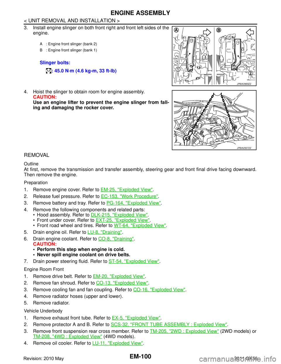
3. Install engine slinger on both front right and front left sides of theengine.
4. Hoist the slinger to obtain room for engine assembly. CAUTION:
Use an engine lifter to prevent the engine slinger from fall-
ing and damaging the rocker cover.
REMOVAL
Outline
At first, remove the transmission and transfer assemb ly, steering gear and front final drive facing downward.
Then remove the engine.
Preparation
1. Remove engine cover. Refer to EM-25, "Exploded View".
2. Release fuel pressure. Refer to EC-153, "
Work Procedure".
3. Remove battery and tray. Refer to PG-164, "
Exploded View".
4. Remove the following components and related parts: Hood assembly. Refer to DLK-215, "
Exploded View".
Front under cover. Refer to EXT-25, "
Exploded View".
Front road wheel and tires. Refer to WT-64, "
Exploded View".
5. Drain engine oil. Refer to LU-8, "
Draining".
6. Drain engine coolant. Refer to CO-8, "
Draining".
CAUTION:
Perform this step when engine is cold.
Never spill engine coolant on drive belts.
7. Drain power steering fluid. Refer to ST-54, "
Exploded View".
Engine Room Front
1. Remove drive belt. Refer to EM-20, "Exploded View".
2. Remove fan shroud. Refer to CO-13, "
Exploded View".
3. Remove cooling fan and fan coupling. Refer to CO-16, "
Exploded View".
4. Remove radiator hoses (upper and lower).
5. Remove radiator.
Vehicle Underbody
1. Remove exhaust front tube. Refer to EX-5, "Exploded View".
2. Remove protector A and B. Refer to SCS-32, "
FRONT TUBE ASSEMBLY : Exploded View".
3. Remove front suspension rear cross member. Refer to TM-205, "
2WD : Exploded View" (2WD models) or
TM-208, "
4WD : Exploded View" (4WD models).
4. Remove oil cooler. Refer to LU-11, "
Exploded View".
A : Engine front slinger (bank 2)
B : Engine front slinger (bank 1)
Slinger bolts:
: 45.0 N·m (4.6 kg-m, 33 ft-lb)
JPBIA3969ZZ
JPBIA2507ZZ
Revision: 2010 May2011 QX56