2011 INFINITI QX56 oil pressure
[x] Cancel search: oil pressurePage 2979 of 5598
ABBREVIATIONSGI-15
< HOW TO USE THIS MANUAL >
C
DE
F
G H
I
J
K L
M B
GI
N
O P
E
F
G
H
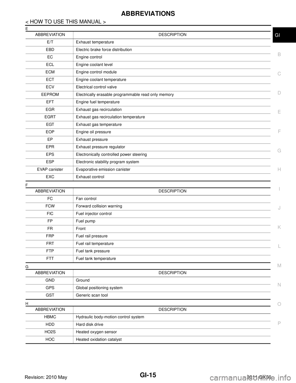
ABBREVIATION DESCRIPTION E/T Exhaust temperature
EBD Electric brake force distribution EC Engine control
ECL Engine coolant level
ECM Engine control module ECT Engine coolant temperature
ECV Electrical control valve
EEPROM Electrically erasable programmable read only memory EFT Engine fuel temperature
EGR Exhaust gas recirculation
EGRT Exhaust gas recirculation temperature EGT Exhaust gas temperature
EOP Engine oil pressure EP Exhaust pressure
EPR Exhaust pressure regulator EPS Electronically controlled power steering
ESP Electronic stability program system
EVAP canister Evaporative emission canister EXC Exhaust control
ABBREVIATION DESCRIPTION FC Fan control
FCW Forward collision warning FIC Fuel injector controlFP Fuel pump
FR Front
FRP Fuel rail pressure FRT Fuel rail temperature
FTP Fuel tank pressure FTT Fuel tank temperature
ABBREVIATION DESCRIPTION GND GroundGPS Global positioning systemGST Generic scan tool
ABBREVIATION DESCRIPTION HBMC Hydraulic body-motion control systemHDD Hard disk drive
HO2S Heated oxygen sensor HOC Heated oxidation catalyst
Revision: 2010 May2011 QX56
Page 3061 of 5598
PRECAUTIONSHA-5
< PRECAUTION >
C
DE
F
G H
J
K L
M A
B
HA
N
O P
- Never allow lubricant (A/C System Oil Type R) to come in contact with styrene foam parts. Damage
may result.
REFRIGERANT CONNECTION
A new type refrigerant connection has been introduced to a ll refrigerant lines except the following location.
Expansion valve to evaporator
Refrigerant pressure sensor to liquid tank
WARNING:
Check that all refrigerant is discharged into the recycling equipment and the pressure in the system is
less than atmospheric pressure. Then gradually loo sen the discharge side hose fitting and remove it.
CAUTION:
Observe the following when replacing or cleaning refrigerant cycle components.
Store it in the same way at it is when mounted on the car when the compressor is removed. Failure
to do so will cause lubricant to enter the low-pressure chamber.
Use always a torque wrench and a b ack-up wrench when connecting tubes.
Plug immediately all openings to prevent entry of dust and mois ture after disconnecting tubes.
Connect the pipes at the final stag e of the operation when installing an air conditioner in the vehicle.
Never remove the seal caps of pipes and other compon ents until just before required for connection.
Allow components stored in cool areas to warm to working area temperature before removing seal
caps. This prevents condensation from forming inside A/C components.
Remove thoroughly moisture from the refriger ation system before charging the refrigerant.
Replace always used O-rings.
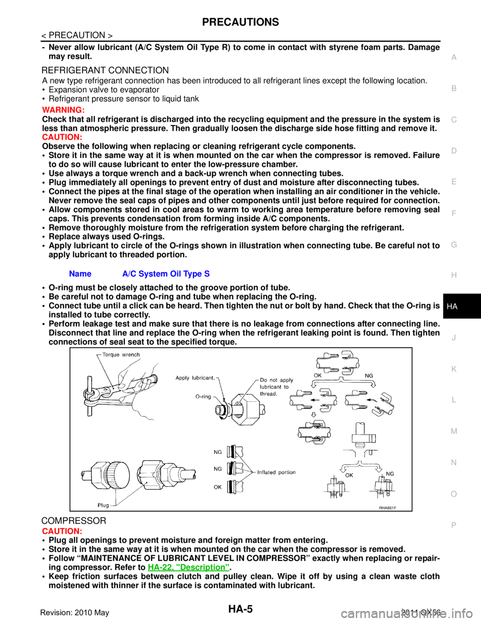
Apply lubricant to circle of th e O-rings shown in illustration when connecting tube. Be careful not to
apply lubricant to threaded portion.
O-ring must be closely attached to the groove portion of tube.
Be careful not to damage O-ring and tube when replacing the O-ring.
Connect tube until a click can be heard. Then tighten the nut or bolt by hand. Check that the O-ring is
installed to tube correctly.
Perform leakage test and make sure that there is no leakage from connections after connecting line.
Disconnect that line and replace the O-ring when the refrigerant leaking point is found. Then tighten
connections of seal seat to the specified torque.
COMPRESSOR
CAUTION:
Plug all openings to prevent moisture and foreign matter from entering.
Store it in the same way at it is when moun ted on the car when the compressor is removed.
Follow “MAINTENANCE OF LUBRICANT LEVEL IN CO MPRESSOR” exactly when replacing or repair-
ing compressor. Refer to HA-22, "
Description".
Keep friction surfaces between clutch and pulley cl ean. Wipe it off by using a clean waste cloth
moistened with thinner if the surface is contaminated with lubricant.
Name A/C System Oil Type S
RHA861F
Revision: 2010 May2011 QX56
Page 3067 of 5598
PREPARATIONHA-11
< PREPARATION >
C
DE
F
G H
J
K L
M A
B
HA
N
O P
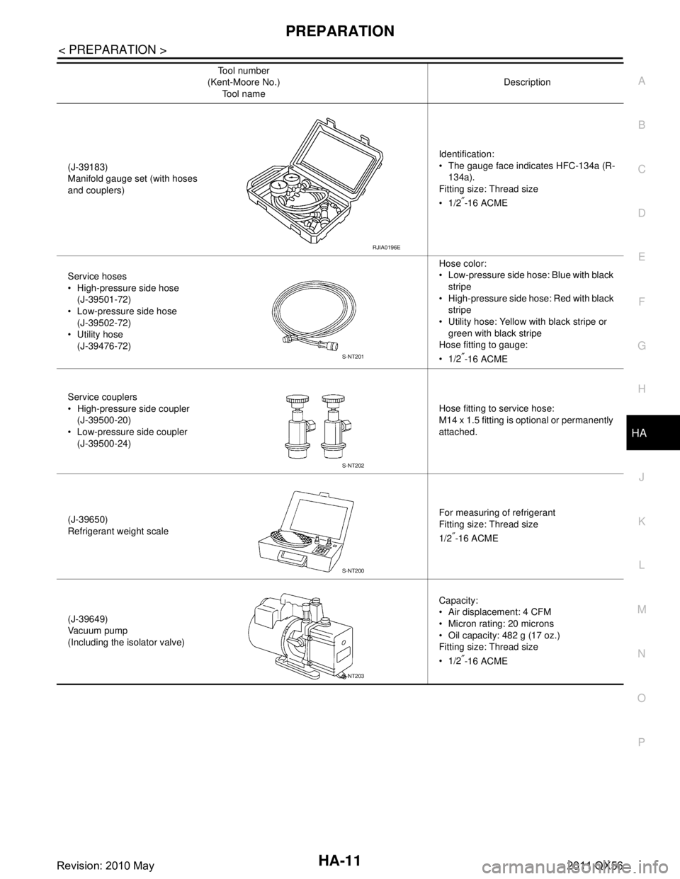
(J-39183)
Manifold gauge set (with hoses
and couplers) Identification:
The gauge face indicates HFC-134a (R-
134a).
Fitting size: Thread size
1/2
″-16 ACME
Service hoses
High-pressure side hose (J-39501-72)
Low-pressure side hose
(J-39502-72)
Utility hose (J-39476-72) Hose color:
Low-pressure side hose: Blue with black
stripe
High-pressure side hose: Red with black stripe
Utility hose: Yellow with black stripe or
green with black stripe
Hose fitting to gauge:
1/2
″-16 ACME
Service couplers
High-pressure side coupler (J-39500-20)
Low-pressure side coupler (J-39500-24) Hose fitting to service hose:
M14 x 1.5 fitting is optional or permanently
attached.
(J-39650)
Refrigerant weight scale For measuring of refrigerant
Fitting size: Thread size
1/2
″-16 ACME
(J-39649)
Va c u u m p u m p
(Including the isolator valve) Capacity:
Air displacement: 4 CFM
Micron rating: 20 microns
Oil capacity: 482 g (17 oz.)
Fitting size: Thread size
1/2
″-16 ACME
Tool number
(Kent-Moore No.)
Tool name Description
RJIA0196E
S-NT201
S-NT202
S-NT200
S-NT203
Revision: 2010 May2011 QX56
Page 3086 of 5598
HA-30
< REMOVAL AND INSTALLATION >
COMPRESSOR
REMOVAL AND INSTALLATION
COMPRESSOR
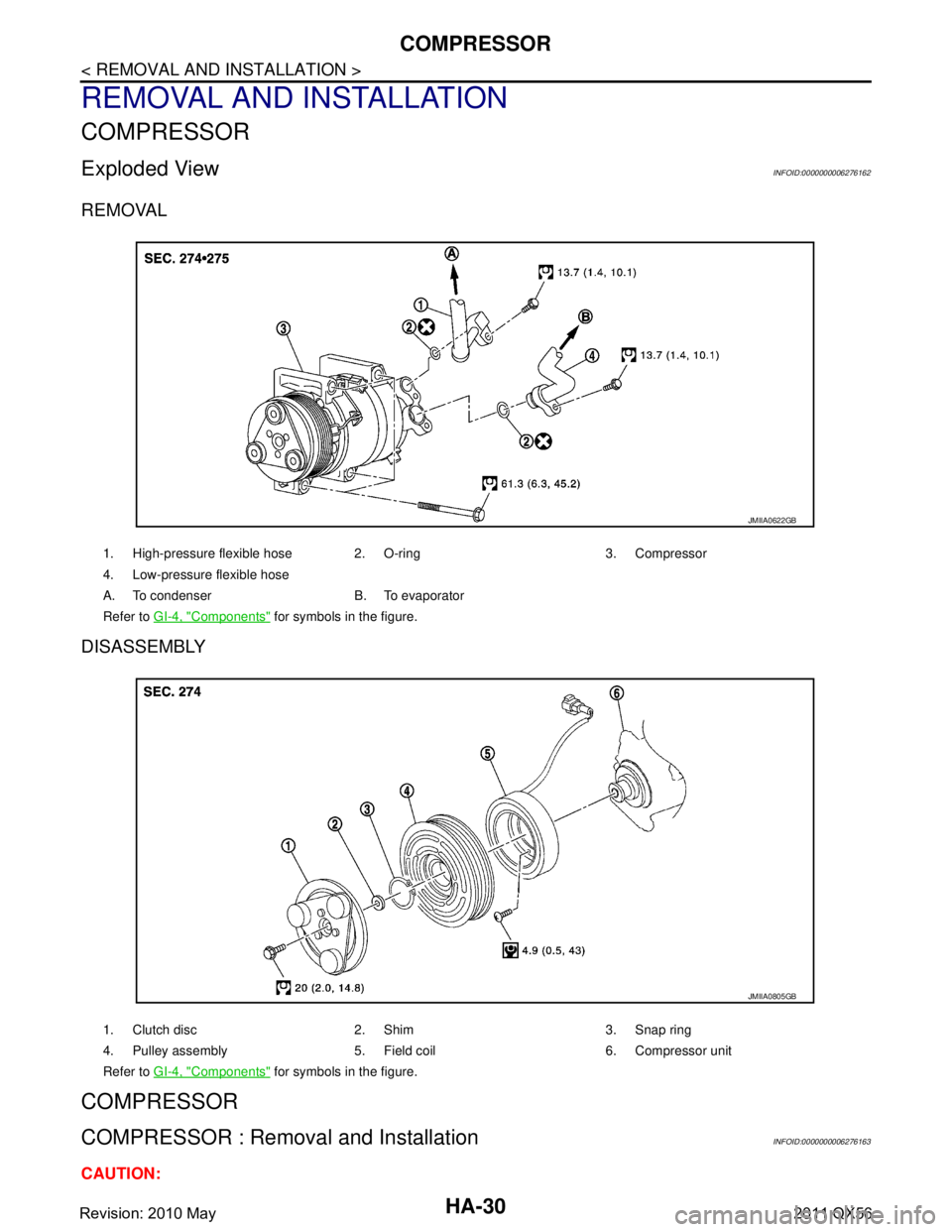
Exploded ViewINFOID:0000000006276162
REMOVAL
DISASSEMBLY
COMPRESSOR
COMPRESSOR : Removal and InstallationINFOID:0000000006276163
CAUTION:
1. High-pressure flexible hose 2. O-ring 3. Compressor
4. Low-pressure flexible hose
A. To condenser B. To evaporator
Refer to GI-4, "
Components" for symbols in the figure.
JMIIA0622GB
1. Clutch disc 2. Shim 3. Snap ring
4. Pulley assembly 5. Field coil 6. Compressor unit
Refer to GI-4, "
Components" for symbols in the figure.
JMIIA0805GB
Revision: 2010 May2011 QX56
Page 3087 of 5598
COMPRESSORHA-31
< REMOVAL AND INSTALLATION >
C
DE
F
G H
J
K L
M A
B
HA
N
O P
Perform lubricant return operati on before each refrigeration system disassembly. However, if a large
amount of refrigerant or lubricant is detected, n ever perform lubricant return operation. Refer to HA-
22, "Perform Lubricant Return Operation".
REMOVAL
1. Use a refrigerant collecting equipment (for HF C-134a) to discharge the refrigerant. Refer to HA-20, "Recy-
cle Refrigerant".
2. Remove air cleaner. Refer to EM-27, "
Removal and Installation".
3. Remove mounting bolts, and then disconnect low-pressure flexible hose and high-pressure flexible hose from the compressor.
CAUTION:
Cap or wrap the joint of the A/C piping and comp ressor with suitable material such as vinyl tape to
avoid the entry of air.
4. Remove front under cover. Refer to EXT-25, "
Exploded View".
5. Remove drive belt. Refer to EM-20, "
Removal and Installation".
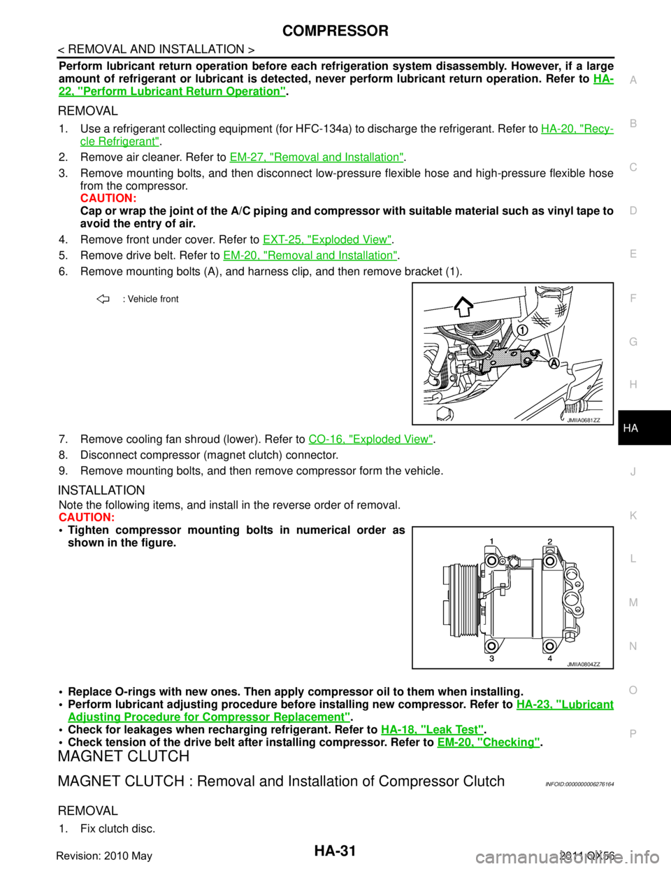
6. Remove mounting bolts (A), and harness clip, and then remove bracket (1).
7. Remove cooling fan shroud (lower). Refer to CO-16, "
Exploded View".
8. Disconnect compressor (magnet clutch) connector.
9. Remove mounting bolts, and then remove compressor form the vehicle.
INSTALLATION
Note the following items, and install in the reverse order of removal.
CAUTION:
Tighten compressor mounting bolts in numerical order as shown in the figure.
Replace O-rings with new ones. Then apply compressor oil to them when installing.
Perform lubricant adjusting procedure befo re installing new compressor. Refer to HA-23, "
Lubricant
Adjusting Procedure for Compressor Replacement".
Check for leakages when recharging refrigerant. Refer to HA-18, "
Leak Test".
Check tension of the drive belt afte r installing compressor. Refer to EM-20, "
Checking".
MAGNET CLUTCH
MAGNET CLUTCH : Removal and Inst allation of Compressor ClutchINFOID:0000000006276164
REMOVAL
1. Fix clutch disc.
: Vehicle front
JMIIA0681ZZ
JMIIA0804ZZ
Revision: 2010 May2011 QX56
Page 3090 of 5598

HA-34
< REMOVAL AND INSTALLATION >
COOLER PIPE AND HOSE
REAR
HIGH-PRESSURE FLEXIBLE HOSE
HIGH-PRESSURE FLEXIBLE HOSE : Removal and InstallationINFOID:0000000006276173
CAUTION:
Perform lubricant return operation before each re frigeration system disassembly. However, if a large
amount of refrigerant or lubrican t is detected, never perform lubricant return operation. Refer to HA-
22, "Perform Lubricant Return Operation".
REMOVAL
1. Use a refrigerant collecting equipment (for HF C-134a) to discharge the refrigerant. Refer to HA-20, "Recy-
cle Refrigerant".
2. Remove air cleaner. Refer to EM-27, "
Removal and Installation".
3. Remove mounting bolt, and then remove high-pressure flexible hose from the vehicle. CAUTION:
Cap or wrap the joint of the A/ C piping, condensor and compressor with suitable material such as
vinyl tape to avoid the entry of air.
INSTALLATION
Note the following items, and install in the reverse order of removal.
CAUTION:
Replace O-rings with new ones. Then apply compressor oil to them when installing.
JMIIA0625GB
1. Rear A/C unit assembly 2. O-ring 3. Clamp
4. Rear cooler & heater pipe assembly 5. Rear heater bypas hose 6. Rear cooler pipe cover
7. Heater hose 8. Front water outlet tube 9. Gromet
10. Clamp 11. Cap 12. Front heater outlet hose
A. To front cooler sycle B. To front heater core C. To cooling sycle
Refer to GI-4, "
Components" for symbols in the figure.
Revision: 2010 May2011 QX56
Page 3091 of 5598
COOLER PIPE AND HOSEHA-35
< REMOVAL AND INSTALLATION >
C
DE
F
G H
J
K L
M A
B
HA
N
O P
Check for leakages when recharging refrigerant. Refer to HA-18, "Leak Test".
LOW-PRESSURE FLEXIBLE HOSE
LOW-PRESSURE FLEXIBLE HOSE : Removal and InstallationINFOID:0000000006276174
CAUTION:
Perform lubricant return operation before each refrigeration system disassembly. However, if a large
amount of refrigerant or lubricant is detected, n ever perform lubricant return operation. Refer to HA-
22, "Perform Lubricant Return Operation".
REMOVAL
1. Use a refrigerant collecting equipment (for HF C-B4a) to discharge the refrigerant. Refer to HA-22, "Per-
form Lubricant Return Operation".
2. Remove air cleaner. Refer to EM-27, "
Removal and Installation".
3. Remove the mounting bolt installed in low-pressure flexible hose from the vehicle.
4. Remove mounting bolts, and then remove low-pressure flexible hose from the vehicle. CAUTION:
Cap or wrap the joint of the A/C piping and comp ressor with suitable material such as vinyl tape to
avoid the entry of air.
INSTALLATION
Note the following items, and install in the reverse order of removal.
CAUTION:
Replace O-rings with new ones. Then apply compressor oil to them when installing.
Check for leakages when recharging refrigerant. Refer to HA-18, "
Leak Test".
HIGH-PRESSURE PIPE
HIGH-PRESSURE PIPE : Removal and InstallationINFOID:0000000006276175
CAUTION:
Perform lubricant return operati on before each refrigeration system disassembly. However, if a large
amount of refrigerant or lubricant is detected, n ever perform lubricant return operation. Refer to HA-
22, "Perform Lubricant Return Operation".
REMOVAL
1. Use a refrigerant collecting equipment (for HF C-134a) to discharge the refrigerant. Refer to HA-22, "Per-
form Lubricant Return Operation".
2. Remove low-pressure pipe. Refer to HA-36, "
LOW-PRESSURE PIPE : Removal and Installation".
3. Remove battery. Refer to PG-164, "
Removal and Installation".
4. Remove mounting bolts, and then remove battery bracket.
5. Disconnect harness connector, harness clip and ground harness for securing work space.
6. Remove mounting bolt, and then disconnec t high-pressure pipe from condenser.
CAUTION:
Cap or wrap the joint of the A/C piping and comp ressor with suitable material such as vinyl tape to
avoid the entry of air.
7. Remove high-pressure pipe mounting nut.
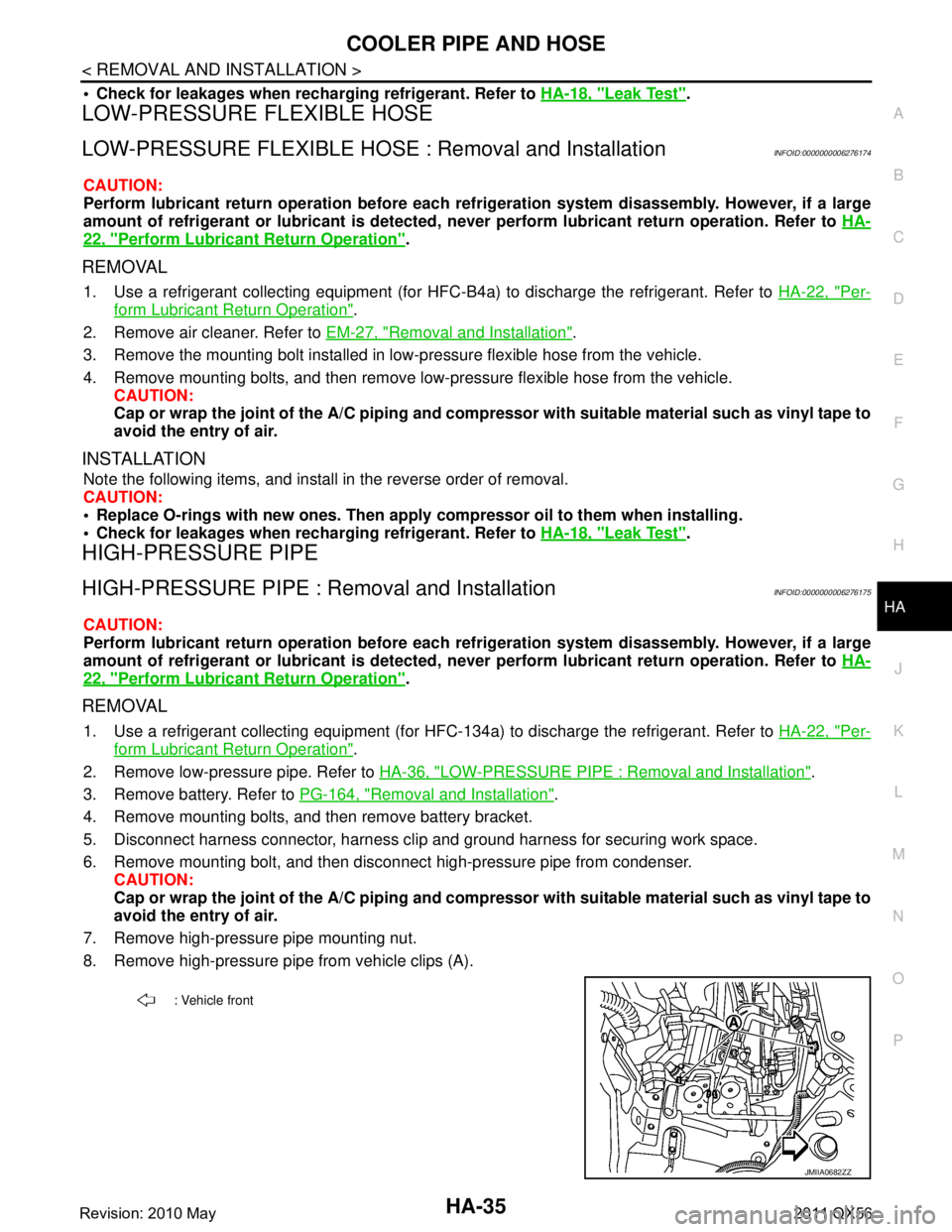
8. Remove high-pressure pipe from vehicle clips (A).
: Vehicle front
JMIIA0682ZZ
Revision: 2010 May2011 QX56
Page 3092 of 5598
HA-36
< REMOVAL AND INSTALLATION >
COOLER PIPE AND HOSE
9. Partly remove rear half of front fender protector RH. Refer to EXT-23, "FENDER PROTECTOR : Exploded
View".
10. Remove high-pressure pipe.
INSTALLATION
Note the following items, and install in the reverse order of removal.
CAUTION:
Replace O-rings with new ones. Then apply compressor oil to them when installing.
Check for leakages when recharging refrigerant. Refer to HA-18, "
Leak Test".
LOW-PRESSURE PIPE
LOW-PRESSURE PIPE : Removal and InstallationINFOID:0000000006276176
CAUTION:
Perform lubricant return operation before each re frigeration system disassembly. However, if a large
amount of refrigerant or lubrican t is detected, never perform lubricant return operation. Refer to HA-
22, "Perform Lubricant Return Operation".
REMOVAL
1. Use a refrigerant collecting equipment (for HF C-134a) to discharge the refrigerant. Refer to HA-22, "Per-
form Lubricant Return Operation".
2. Drain engine coolant from cooling system. Refer to CO-8, "
Draining".
3. Remove engine cover. Refer to EM-25, "
Removal and Installation".
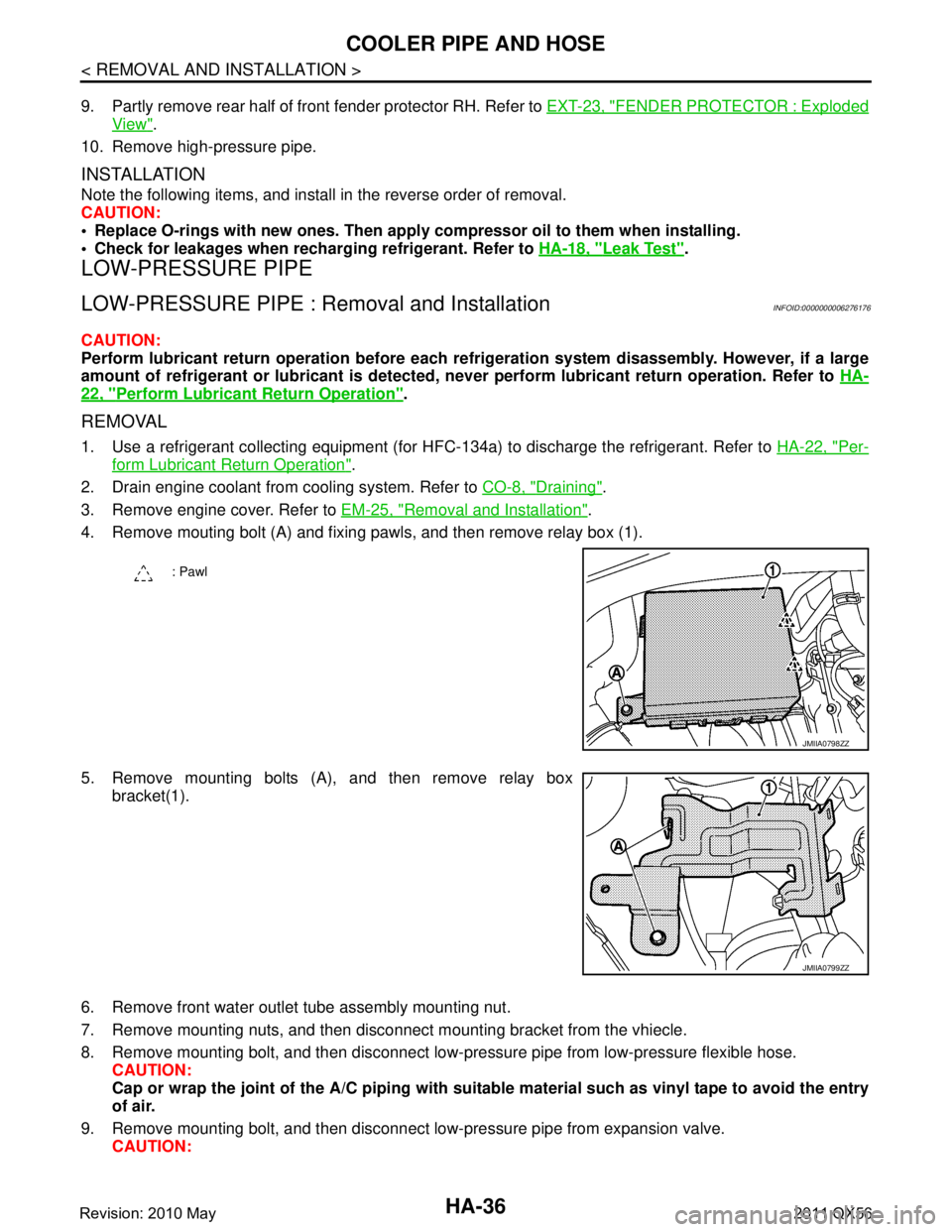
4. Remove mouting bolt (A) and fixing pawls, and then remove relay box (1).
5. Remove mounting bolts (A), and then remove relay box bracket(1).
6. Remove front water outlet tube assembly mounting nut.
7. Remove mounting nuts, and then disconnec t mounting bracket from the vhiecle.
8. Remove mounting bolt, and then disconnect low-pressure pipe from low-pressure flexible hose. CAUTION:
Cap or wrap the joint of the A/C piping with suitab le material such as vinyl tape to avoid the entry
of air.
9. Remove mounting bolt, and then disconnect low-pressure pipe from expansion valve. CAUTION:
: Pawl
JMIIA0798ZZ
JMIIA0799ZZ
Revision: 2010 May2011 QX56