2011 INFINITI QX56 torque
[x] Cancel search: torquePage 3698 of 5598
MA-28
< PERIODIC MAINTENANCE >
CHASSIS MAINTENANCE
BRAKE FLUID LEVEL AND LEAKS : Inspection
INFOID:0000000006220939
Check that the fluid level in the sub tank is within the specified range (MAX – MIN lines).
CAUTION:
Turn OFF the ignition switch an d depress the brake pedal 20 times or more to check brake fluid level.
NOTE:
Since brake fluid is in the accumulator in pressurized condition, the reservoir tank brake fluid level should be
lower than the MAX line.
Visually check for any brake fluid leakage around the reservoir tank.
Check the brake system for any leakage if the fl uid level is extremely low (lower than MIN).
Check the brake system for fluid leakage if the warn ing lamp remains illuminated even after the parking
brake is released.
Check the sub tank for the mixing of foreign ma tter (e.g. dust) and oils other than brake fluid.
BRAKE LINES AND CABLES
BRAKE LINES AND CABLES : InspectionINFOID:0000000006220940
1. Check brake line (tubes and hoses) for cracks, deterioration or other damage. Replace any damaged
parts.
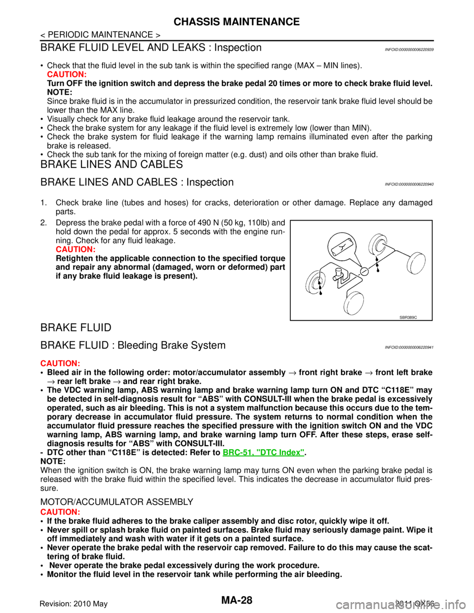
2. Depress the brake pedal with a force of 490 N (50 kg, 110lb) and hold down the pedal for approx. 5 seconds with the engine run-
ning. Check for any fluid leakage.
CAUTION:
Retighten the applicable conn ection to the specified torque
and repair any abnormal (damag ed, worn or deformed) part
if any brake fluid leakage is present).
BRAKE FLUID
BRAKE FLUID : Bleeding Brake SystemINFOID:0000000006220941
CAUTION:
Bleed air in the following order: motor/accumulator assembly → front right brake → front left brake
→ rear left brake → and rear right brake.
The VDC warning lamp, ABS warning lamp and br ake warning lamp turn ON and DTC “C118E” may
be detected in self-diagnosis r esult for “ABS” with CONSULT-II I when the brake pedal is excessively
operated, such as air bleeding. Thi s is not a system malfunction becau se this occurs due to the tem-
porary decrease in accumulator fl uid pressure. The system returns to normal condition when the
accumulator fluid pressure reaches the specified pressu re with the ignition switch ON and the VDC
warning lamp, ABS warning lamp, and brake warnin g lamp turn OFF. After these steps, erase self-
diagnosis results for “ABS” with CONSULT-III.
- DTC other than “C118E” is detected: Refer to BRC-51, "
DTC Index".
NOTE:
When the ignition switch is ON, the brake warning la mp may turns ON even when the parking brake pedal is
released with the brake fluid within the specified level. This indicates the decrease in accumulator fluid pres-
sure.
MOTOR/ACCUMULATOR ASSEMBLY
CAUTION:
If the brake fluid adheres to the brake caliper assembly and disc rotor, quickly wipe it off.
Never spill or splash brake fluid on painted surfaces. Brake fluid may seriously damage paint. Wipe it
off immediately and wash with wate r if it gets on a painted surface.
Never operate the brake pedal with the reservoir cap removed. Failure to do this may cause the scat-
tering of brake fluid.
Never operate the brake pedal excessively during the work procedure.
Monitor the fluid level in the reservoir tank while performing the air bleeding.
SBR389C
Revision: 2010 May2011 QX56
Page 3699 of 5598
CHASSIS MAINTENANCEMA-29
< PERIODIC MAINTENANCE >
C
DE
F
G H
I
J
K L
M B
MA
N
O A
Bleed air in the following
order: motor/accumulator assembly → front right brake → front left brake
→ rear left brake → and rear right brake.
1. Turn the ignition switch OFF.
2. Depress the brake pedal 20 times or more.
3. Check that there is no foreign material in t he reservoir tank, and refill with new brake fluid.
CAUTION:
Never reuse drained brake fluid.
Never allow oils other than brake fl uid to enter the reservoir tank.
4. Turn the ignition switch ON. NOTE:
The motor is activated and automatically stops.
5. Turn the ignition switch OFF.
6. Depress the brake pedal 20 times or more. NOTE:
The pressure loss in the accumulator results in a large brake pedal stroke. In addition to this, the brake
pedal depression becomes lighter in initial stage.
7. Repeat steps 4 to 6 for 5 times.
8. Turn the ignition switch ON to check that the time between motor activation and automatic stop is less
than 18 seconds. If the time is 18 seconds or more, repeat from Step 4 to 8.
FRONT BRAKE
CAUTION:
If the brake fluid adheres to the brake caliper assembly and disc rotor, quickly wipe it off.
Never spill or splash brake fluid on painted surfaces. Brake fluid may seriously damage paint. Wipe it
off immediately and wash with wate r if it gets on a painted surface.
Never operate the brake pedal with the reservoir cap removed. Failure to do this may cause the scat-
tering of brake fluid.
Never operate the brake pedal excessively during the work procedure.
Monitor the fluid level in the reservoir tank while performing the air bleeding.
Bleed air in the following order: motor/accumulator assembly → front right brake → front left brake
→ rear left brake → and rear right brake.
1. Turn the ignition switch OFF.
2. Depress the brake pedal 20 times or more. NOTE:
The pressure loss in the accumulator results in a large brake pedal stroke. In addition to this, the brake
pedal depression becomes lighter in initial stage.
3. Check that there is no foreign material in t he reservoir tank, and refill with new brake fluid.
CAUTION:
Never reuse drained brake fluid.
Never allow oils other than brake fl uid to enter the reservoir tank.
4. Turn the ignition switch ON.
5. Connect a vinyl tube to the bleed valve.
6. Depress the brake pedal and loosen the bleeder valve.
7. Repeat steps 1 to 6 until all of the air is out of the brake line and tighten the air bleeder to the specified
torque with the brake pedal depressed. Refer to BR-36, "
BRAKE CALIPER ASSEMBLY : Exploded View".
8. Check that no drag feel is present for the front disc brake. Refer to BR-39, "
BRAKE CALIPER ASSEMBLY
: Inspection".
9. Check each item of brake pedal. Adjust it if t he measurement value is not the standard. Refer to BR-7,
"Inspection and Adjustment".
REAR BRAKE
CAUTION:
If the brake fluid adheres to the brake caliper assembly and disc rotor, quickly wipe it off.
Never spill or splash brake fluid on painted surfaces. Brake fluid may seriously damage paint. Wipe it
off immediately and wash with wate r if it gets on a painted surface.
Never operate the brake pedal with the reservoir cap removed. Failure to do this may cause the scat-
tering of brake fluid.
Revision: 2010 May2011 QX56
Page 3700 of 5598
MA-30
< PERIODIC MAINTENANCE >
CHASSIS MAINTENANCE
Never operate the brake pedal excessively during the work procedure.
Monitor the fluid level in the reservoir tank while performing the air bleeding.
Bleed air in the following order: motor/accumulator assembly → front right brake → front left brake
→ rear left brake → and rear right brake.
1. Turn the ignition switch OFF.
2. Depress the brake pedal 20 times or more. NOTE:
The pressure loss in the accumulator results in a large brake pedal stroke. In addition to this, the brake
pedal depression becomes lighter in initial stage.
3. Check that there is no foreign material in the reservoir tank, and refill with new brake fluid. CAUTION:
Never reuse drained brake fluid.
Never allow oils other than brake fluid to enter the reservoir tank.
4. Turn the ignition switch ON.
5. Connect a vinyl tube to the bleed valve.
6. Depress the brake pedal and loosen the bleeder valve.
7. Depress and hold the brake pedal depression to dischar ge 100 cc of brake fluid before tightening the air
bleeder to the specified torque. Refer to BR-42, "
BRAKE CALIPER ASSEMBLY : Exploded View".
NOTE:
Since brake fluid is conveyed by the motor, the brake pedal is not necessarily depressed.
8. Release the brake pedal.
9. Repeat steps 1 to 8 until all of the air is out of the brake line and tighten the air bleeder to the specified
torque with the brake pedal depressed. Refer to BR-42, "
BRAKE CALIPER ASSEMBLY : Exploded View".
10. Check that no drag feel is present for the rear disc brake. Refer to BR-45, "
BRAKE CALIPER ASSEMBLY
: Inspection".
11. Check each item of brake pedal. Adjust it if t he measurement value is not the standard. Refer to BR-7,
"Inspection and Adjustment".
BRAKE FLUID LEVEL ADJUSTMENT AFTER AIR BLEEDING
1. Turn the ignition switch OFF.
2. Depress the brake pedal 20 times or more.
NOTE:
The pressure loss in the accumulator results in a large brake pedal stroke. In addition to this, the brake
pedal depression becomes lighter in initial stage.
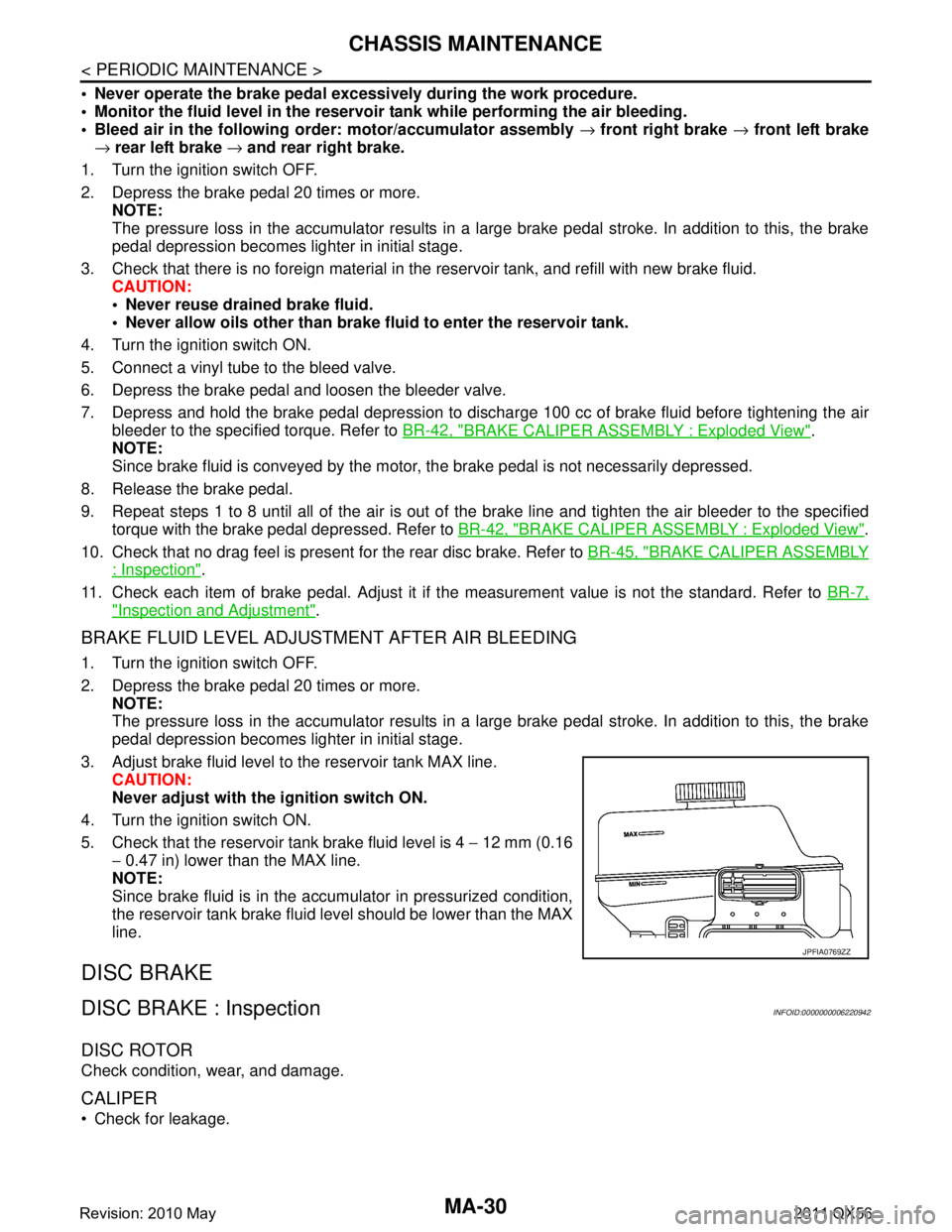
3. Adjust brake fluid level to the reservoir tank MAX line. CAUTION:
Never adjust with the ignition switch ON.
4. Turn the ignition switch ON.
5. Check that the reservoir tank brake fluid level is 4 − 12 mm (0.16
− 0.47 in) lower than the MAX line.
NOTE:
Since brake fluid is in the accumulator in pressurized condition,
the reservoir tank brake fluid level should be lower than the MAX
line.
DISC BRAKE
DISC BRAKE : InspectionINFOID:0000000006220942
DISC ROTOR
Check condition, wear, and damage.
CALIPER
Check for leakage.
JPFIA0769ZZ
Revision: 2010 May2011 QX56
Page 4205 of 5598
REAR WHEEL HUB AND HOUSINGRAX-9
< REMOVAL AND INSTALLATION >
CEF
G H
I
J
K L
M A
B
RAX
N
O P
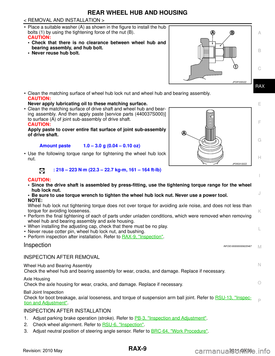
Place a suitable washer (A) as shown in the figure to install the hub bolts (1) by using the tightening force of the nut (B).
CAUTION:
Check that there is no cl earance between wheel hub and
bearing assembly, and hub bolt.
Never reuse hub bolt.
Clean the matching surface of wheel hub lock nut and wheel hub and bearing assembly. CAUTION:
Never apply lubricating oi l to these matching surface.
Clean the matching surface of drive shaft and wheel hub and bear-
ing assembly. And then apply paste [service parts (440037S000)]
to surface (A) of joint sub-assembly of drive shaft.
CAUTION:
Apply paste to cover entire fl at surface of joint sub-assembly
of drive shaft.
Use the following torque range for tightening the wheel hub lock nut.
CAUTION:
Since the drive shaft is assembled by press-fitting , use the tightening torque range for the wheel
hub lock nut.
Be sure to use torque wrench to tighten th e wheel hub lock nut. Never use a power tool.
NOTE:
Wheel hub lock nut tightening torque does not over tor que for avoiding axle noise, and does not less than
torque for avoiding looseness.
Perform the final tightening of each of parts under unladen conditions, which were removed when removing wheel hub and bearing assembly and axle housing.
When installing the adjusting cap, check that there must be no play.
Never reuse cotter pin, wheel hub lock nut, and bushing.
Perform inspection after installation. Refer to RAX-9, "
Inspection".
InspectionINFOID:0000000006225467
INSPECTION AFTER REMOVAL
Wheel Hub and Bearing Assembly
Check the wheel hub and bearing assembly for wear, cracks, and damage. Replace if necessary.
Axle Housing
Check the axle housing for wear, cracks, and damage. Replace if necessary.
Ball Joint Inspection
Check for boot breakage, axial looseness, and torque of suspension arm ball joint. Refer to RSU-13, "Inspec-
tion and Adjustment".
INSPECTION AFTER INSTALLATION
1. Adjust parking brake operation (stroke). Refer to PB-3, "Inspection and Adjustment".
2. Check wheel alignment. Refer to RSU-6, "
Inspection".
3. Adjust neutral position of steering angle sensor. Refer to BRC-64, "
Work Procedure".
JPDIF0300ZZ
Amount paste 1.0 – 3.0 g (0.04 – 0.10 oz)
: 218 – 223 N·m (22.3 – 22.7 kg-m, 161 – 164 ft-lb)
JPDIG0122ZZ
Revision: 2010 May2011 QX56
Page 4208 of 5598
RAX-12
< REMOVAL AND INSTALLATION >
REAR DRIVE SHAFT
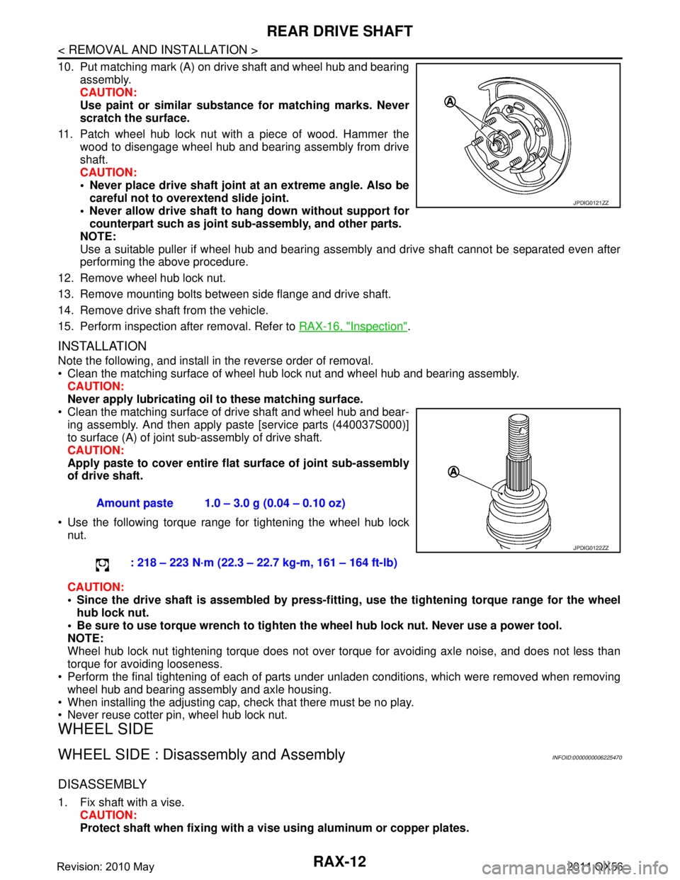
10. Put matching mark (A) on drive shaft and wheel hub and bearingassembly.
CAUTION:
Use paint or similar substance for matching marks. Never
scratch the surface.
11. Patch wheel hub lock nut with a piece of wood. Hammer the wood to disengage wheel hub and bearing assembly from drive
shaft.
CAUTION:
Never place drive shaft joint at an extreme angle. Also becareful not to over extend slide joint.
Never allow drive shaft to ha ng down without support for
counterpart such as joint sub-assembly, and other parts.
NOTE:
Use a suitable puller if wheel hub and bearing assembly and drive shaft cannot be separated even after
performing the above procedure.
12. Remove wheel hub lock nut.
13. Remove mounting bolts between side flange and drive shaft.
14. Remove drive shaft from the vehicle.
15. Perform inspection after removal. Refer to RAX-16, "
Inspection".
INSTALLATION
Note the following, and install in the reverse order of removal.
Clean the matching surface of wheel hub lock nut and wheel hub and bearing assembly.
CAUTION:
Never apply lubricating oi l to these matching surface.
Clean the matching surface of drive shaft and wheel hub and bear- ing assembly. And then apply paste [service parts (440037S000)]
to surface (A) of joint sub-assembly of drive shaft.
CAUTION:
Apply paste to cover entire fl at surface of joint sub-assembly
of drive shaft.
Use the following torque range for tightening the wheel hub lock nut.
CAUTION:
Since the drive shaft is assembled by press-fittin g, use the tightening torque range for the wheel
hub lock nut.
Be sure to use torque wrench to tighten th e wheel hub lock nut. Never use a power tool.
NOTE:
Wheel hub lock nut tightening torque does not over torque for avoiding axle noise, and does not less than
torque for avoiding looseness.
Perform the final tightening of each of parts under unladen conditions, which were removed when removing
wheel hub and bearing assembly and axle housing.
When installing the adjusting cap, check that there must be no play.
Never reuse cotter pin, wheel hub lock nut.
WHEEL SIDE
WHEEL SIDE : Disassembly and AssemblyINFOID:0000000006225470
DISASSEMBLY
1. Fix shaft with a vise. CAUTION:
Protect shaft when fixing with a vi se using aluminum or copper plates.
JPDIG0121ZZ
Amount paste 1.0 – 3.0 g (0.04 – 0.10 oz)
: 218 – 223 N·m (22.3 – 22.7 kg-m, 161 – 164 ft-lb)
JPDIG0122ZZ
Revision: 2010 May2011 QX56
Page 4262 of 5598
WHEEL ALIGNMENTRSU-7
< PERIODIC MAINTENANCE >
C
DF
G H
I
J
K L
M A
B
RSU
N
O P
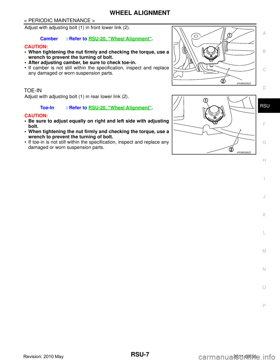
Adjust with adjusting bolt (1) in front lower link (2).
CAUTION:
When tightening the nut firml y and checking the torque, use a
wrench to prevent the turning of bolt.
After adjusting camber, be sure to check toe-in.
If camber is not still within the specification, inspect and replace
any damaged or worn suspension parts.
TOE-IN
Adjust with adjusting bolt (1) in rear lower link (2).
CAUTION:
Be sure to adjust equally on ri ght and left side with adjusting
bolt.
When tightening the nut firml y and checking the torque, use a
wrench to prevent the turning of bolt.
If toe-in is not still within the specification, inspect and replace any damaged or worn suspension parts. Camber : Refer to
RSU-20, "
Wheel Alignment".
JPEIB0225ZZ
Toe-In : Refer to RSU-20, "Wheel Alignment".
JPEIB0226ZZ
Revision: 2010 May2011 QX56
Page 4268 of 5598
SUSPENSION ARMRSU-13
< REMOVAL AND INSTALLATION >
C
DF
G H
I
J
K L
M A
B
RSU
N
O P
SUSPENSION ARM
Exploded ViewINFOID:0000000006225670
Removal and InstallationINFOID:0000000006225671
REMOVAL
1. Remove tires with power tool. Refer to WT-64, "Removal and Installation".
2. Remove rear suspension member assembly. Refer to RSU-18, "
Removal and Installation".
3. Remove bumper rubber from frame, usi ng a socket (commercial service tool).
4. Remove suspension arm from axle housing. Refer to RAX-7, "
Removal and Installation".
5. Remove suspension arm mounting bolts, nuts, and stopper rubber from rear suspension member.
6. Remove suspension arm.
7. Perform inspection after removal. Refer to RSU-13, "
Inspection and Adjustment".
INSTALLATION
Note the following and, install in the reverse order of removal.
Perform final tightening of rear suspension mem ber installation position (rubber bussing), under unladen
conditions with tires on level ground.
Perform inspection after installation. Refer to RSU-13, "
Inspection and Adjustment".
Perform adjustment after installation. (With HBMC) Refer to RSU-13, "
Inspection and Adjustment".
Inspection and AdjustmentINFOID:0000000006225672
INSPECTION AFTER REMOVAL
Appearance
Check the following items, and replace the part if necessary.
Suspension arm and bushing for deformation, cracks or damage.
Boot of ball joint for cracks or damage, and also for grease leakage.
Ball Joint Inspection
Manually move ball stud to confirm it moves smoothly with no binding.
Swing Torque Inspection
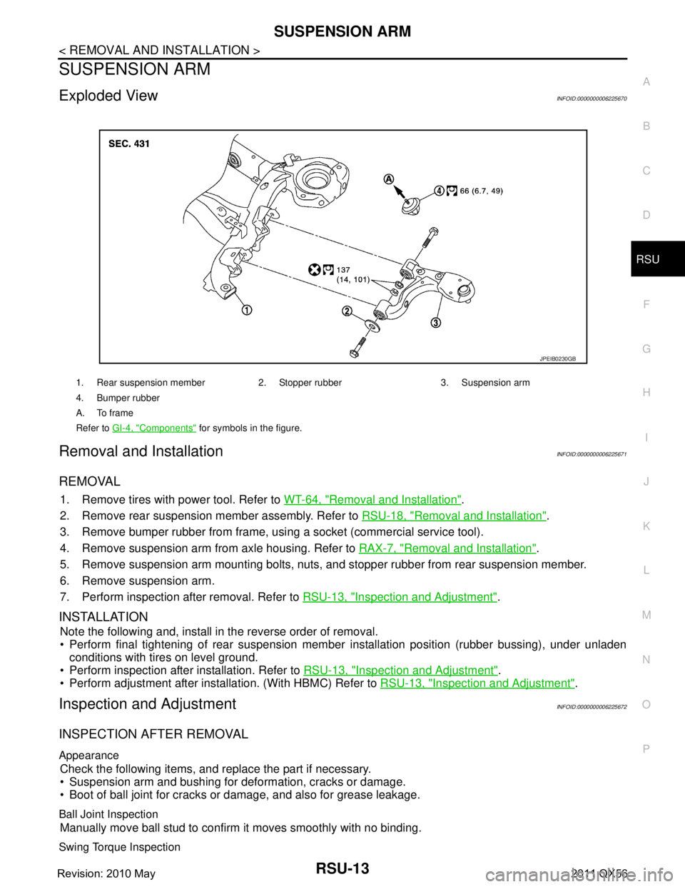
1. Rear suspension member 2. Stopper rubber 3. Suspension arm
4. Bumper rubber
A. To frame
Refer to GI-4, "
Components" for symbols in the figure.
JPEIB0230GB
Revision: 2010 May2011 QX56
Page 4269 of 5598
RSU-14
< REMOVAL AND INSTALLATION >
SUSPENSION ARM
1. Move the ball joint at least ten times by hand to check for smooth movement.
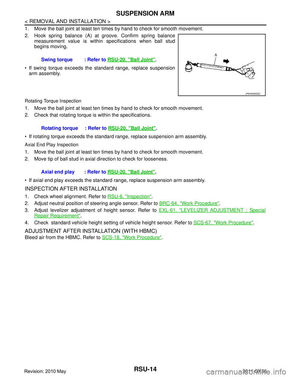
2. Hook spring balance (A) at groove. Confirm spring balancemeasurement value is within specifications when ball stud
begins moving.
If swing torque exceeds the standard range, replace suspension arm assembly.
Rotating Torque Inspection
1. Move the ball joint at least ten times by hand to check for smooth movement.
2. Check that rotating torque is within the specifications.
If rotating torque exceeds the standard range, replace suspension arm assembly.
Axial End Play Inspection
1. Move the ball joint at least ten times by hand to check for smooth movement.
2. Move tip of ball stud in axial direction to check for looseness.
If axial end play exceeds the standard r ange, replace suspension arm assembly.
INSPECTION AFTER INSTALLATION
1. Check wheel alignment. Refer to RSU-6, "Inspection".
2. Adjust neutral position of steering angle sensor. Refer to BRC-64, "
Work Procedure".
3. Adjust levelizer adjustment of height sensor. Refer to EXL-61, "
LEVELIZER ADJUSTMENT : Special
Repair Requirement".
4. Check standard vehicle height setting of vehicle height sensor. Refer to SCS-67, "
Work Procedure".
ADJUSTMENT AFTER INSTALLATION (WITH HBMC)
Bleed air from the HBMC. Refer to SCS-18, "Work Procedure".
Swing torque : Refer to
RSU-20, "
Ball Joint".
JPEIA0005ZZ
Rotating torque : Refer to RSU-20, "Ball Joint".
Axial end play : Refer to RSU-20, "
Ball Joint".
Revision: 2010 May2011 QX56