2011 INFINITI QX56 torque
[x] Cancel search: torquePage 2710 of 5598
![INFINITI QX56 2011 Factory Service Manual
EX-6
< REMOVAL AND INSTALLATION >
EXHAUST SYSTEM
- Using heated oxygen sensor wrench [SST: KV10114400] (C),removal heated oxygen sensor 2.
INSTALLATION
Note the following items, and install in the re INFINITI QX56 2011 Factory Service Manual
EX-6
< REMOVAL AND INSTALLATION >
EXHAUST SYSTEM
- Using heated oxygen sensor wrench [SST: KV10114400] (C),removal heated oxygen sensor 2.
INSTALLATION
Note the following items, and install in the re](/manual-img/42/57033/w960_57033-2709.png)
EX-6
< REMOVAL AND INSTALLATION >
EXHAUST SYSTEM
- Using heated oxygen sensor wrench [SST: KV10114400] (C),removal heated oxygen sensor 2.
INSTALLATION
Note the following items, and install in the reverse order of removal.
Temporarily tighten bolts and nuts when installing exhaust pipe assembly. Tighten them to the specifiedtorque when connecting the vehicle rear to the vehicle front.
CAUTION:
Always replace exhaust tube gasket s with new ones when reassembling.
If heat insulator is badly deformed, repair or re place it. If deposits such as mud pile up on the heat
insulator, remove them.
When installing heat insulator avoid large gaps or interference between heat insulator and each
exhaust pipe.
Remove deposits from the sealing surface of each connection. Connect them securely to avoid
gases leakage.
Check each part for unusual interference, and then tighten them to the specified torque.
When installing each moun ting rubber, avoid twisting or unusua l extension in up/down and right/left
directions.
InspectionINFOID:0000000006289697
INSPECTION AFTER INSTALLATION
Check clearance between tail tube and rear bumper is even.
With engine running, check exhaust tube joints for gas leakage and unusual noises.
Check to ensure that mounting brackets and mounting rubbers are installed properly and free from undue stress. Improper installation could result in excessive noise and vibration.
A: Bank 1
B: Bank 2
: Vehicle front
JPBIA3395ZZ
Revision: 2010 May2011 QX56
Page 2909 of 5598
![INFINITI QX56 2011 Factory Service Manual
FRONT WHEEL HUB AND KNUCKLEFAX-9
< REMOVAL AND INSTALLATION > [2WD]
C
EF
G H
I
J
K L
M A
B
FA X
N
O P
8. Remove shock absorber mounting bolt from lower link. Refer to FSU-10, "Removal and Installati INFINITI QX56 2011 Factory Service Manual
FRONT WHEEL HUB AND KNUCKLEFAX-9
< REMOVAL AND INSTALLATION > [2WD]
C
EF
G H
I
J
K L
M A
B
FA X
N
O P
8. Remove shock absorber mounting bolt from lower link. Refer to FSU-10, "Removal and Installati](/manual-img/42/57033/w960_57033-2908.png)
FRONT WHEEL HUB AND KNUCKLEFAX-9
< REMOVAL AND INSTALLATION > [2WD]
C
EF
G H
I
J
K L
M A
B
FA X
N
O P
8. Remove shock absorber mounting bolt from lower link. Refer to FSU-10, "Removal and Installation".
9. Separate upper link from steering knuckle, using the ball joint remover (commercial service tool), and
remove upper link.
CAUTION:
Temporarily tighten the nut to prevent damage to threads and to prevent the ball joint remover
from suddenly coming off.
Never damage ball joint boot.
10. Remove wheel hub and bearing assembly, and then remove splash guard.
11. Remove lower link from steering knuckle. CAUTION:
Never damage ball joint boot.
12. Remove steering knuckle.
13. Remove hub bolts (1) from wheel hub and bearing assembly, using the ball joint remover (A) (commercial service tool).
CAUTION:
Remove hub bolt only when necessary.
Never hammer the hub bolt to avoid impact to the wheel
hub and bearing assembly.
Pull out the hub bolt in a di rection perpendicular to the
wheel hub and bearing assembly.
14. Perform inspection after removal. Refer to FAX-9, "
Inspection".
INSTALLATION
Note the following, and install in the reverse order of removal.
Place a suitable washer (A) as shown in the figure to install the hub
bolts (1) by using the tightening force of the nut (B).
CAUTION:
Check that there is no cl earance between wheel hub and
bearing assembly, and hub bolt.
Never reuse hub bolt.
Perform the final tightening of each of parts under unladen condi-
tions, which were removed when removing wheel hub and bearing
assembly and steering knuckle.
Never reuse cotter pin.
Perform inspection after installation. Refer to FA X - 9 , "
Inspection".
InspectionINFOID:0000000006225420
INSPECTION AFTER REMOVAL
Check components for deformation, cracks, and other damage. Replace it if necessary.
Ball Joint Inspection
Check boots of lower link and steering outer socket ba ll joint for breakage, axial play, and torque. Refer to
FSU-15, "
Inspection" and ST-46, "Inspection".
INSPECTION AFTER INSTALLATION
1. Check wheel sensor harness for proper connection. Refer to BRC-134, "FRONT WHEEL SENSOR :
Exploded View".
2. Check the wheel alignment. Refer to FSU-7, "
Inspection".
3. Adjust neutral position of steering angle sensor. Refer to BRC-64, "
Work Procedure".
JPDIF0299ZZ
JPDIF0300ZZ
Revision: 2010 May2011 QX56
Page 2919 of 5598
![INFINITI QX56 2011 Factory Service Manual
FRONT WHEEL HUB AND KNUCKLEFAX-19
< REMOVAL AND INSTALLATION > [4WD]
C
EF
G H
I
J
K L
M A
B
FA X
N
O P
7. Set suitable jack under lower link.
8. Remove shock absorber mounting bolt from lower link. R INFINITI QX56 2011 Factory Service Manual
FRONT WHEEL HUB AND KNUCKLEFAX-19
< REMOVAL AND INSTALLATION > [4WD]
C
EF
G H
I
J
K L
M A
B
FA X
N
O P
7. Set suitable jack under lower link.
8. Remove shock absorber mounting bolt from lower link. R](/manual-img/42/57033/w960_57033-2918.png)
FRONT WHEEL HUB AND KNUCKLEFAX-19
< REMOVAL AND INSTALLATION > [4WD]
C
EF
G H
I
J
K L
M A
B
FA X
N
O P
7. Set suitable jack under lower link.
8. Remove shock absorber mounting bolt from lower link. Refer to FSU-10, "
Removal and Installation".
9. Separate upper link from steering knuckle, using the ball joint remover (commercial service tool), and
remove upper link.
CAUTION:
Temporarily tighten the nut to prevent damage to threads and to prevent the ball joint remover
from suddenly coming off.
Never damage ball joint boot.
10. Remove cotter pin, and then loosen wheel hub lock nut.
11. Put matching mark on drive shaft and wheel hub and bearing assembly. CAUTION:
Use paint or similar substance for matc hing marks. Never scratch the surface.
12. Patch wheel hub lock nut with a piece of wood. Hammer the wood to disengage wheel hub and bearing assembly from drive shaft.
CAUTION:
Never place drive shaft joint at an extreme angle. Also be careful not to overextend slide joint.
Never allow drive shaft to hang down without support for or joint sub-assembly, shaft and the
other parts.
NOTE:
Use suitable puller, if wheel hub and bearing assembly and drive shaft cannot be separated even after
performing the above procedure.
13. Remove wheel hub lock nut.
14. Remove wheel hub and bearing assembly, and then remove splash guard.
15. Remove lower link from steering knuckle. CAUTION:
Never damage ball joint boot.
16. Remove steering knuckle.
17. Remove hub bolts (1) from wheel hub and bearing assembly, using the ball joint remover (A) (commercial service tool).
CAUTION:
Remove hub bolt only when necessary.
Never hammer the hub bolt to avoid impact to the wheel
hub and bearing assembly.
Pull out the hub bolt in a di rection perpendicular to the
wheel hub and bearing assembly.
18. Perform inspection after removal. Refer to FAX-20, "
Inspection".
INSTALLATION
Note the following, and install in the reverse order of removal.
Place a suitable washer (A) as shown in the figure to install the hub
bolts (1) by using the tightening force of the nut (B).
CAUTION:
Check that there is no cl earance between wheel hub and
bearing assembly, and hub bolt.
Never reuse hub bolt.
Use the following torque range for tightening the wheel hub lock nut.
CAUTION:
Since the drive shaft is assembled by press-fitting , use the tightening torque range for the wheel
hub lock nut.
Be sure to use torque wrench to tighten th e wheel hub lock nut. Never use a power tool.
Perform the final tightening of each of parts under unladen conditions, which were removed when removing
wheel hub and bearing assembly and steering knuckle.
JPDIF0299ZZ
: 118 – 123 N·m (12.1 – 12.5 kg-m, 87 – 90 ft-lb)
JPDIF0300ZZ
Revision: 2010 May2011 QX56
Page 2920 of 5598
![INFINITI QX56 2011 Factory Service Manual
FAX-20
< REMOVAL AND INSTALLATION >[4WD]
FRONT WHEEL HUB AND KNUCKLE
Never reuse cotter pin.
Perform inspection after installation. Refer to
FAX-20, "
Inspection".
InspectionINFOID:0000000006225 INFINITI QX56 2011 Factory Service Manual
FAX-20
< REMOVAL AND INSTALLATION >[4WD]
FRONT WHEEL HUB AND KNUCKLE
Never reuse cotter pin.
Perform inspection after installation. Refer to
FAX-20, "
Inspection".
InspectionINFOID:0000000006225](/manual-img/42/57033/w960_57033-2919.png)
FAX-20
< REMOVAL AND INSTALLATION >[4WD]
FRONT WHEEL HUB AND KNUCKLE
Never reuse cotter pin.
Perform inspection after installation. Refer to
FAX-20, "
Inspection".
InspectionINFOID:0000000006225398
INSPECTION AFTER REMOVAL
Check components for deformation, cracks, and other damage. Replace it if necessary.
Ball Joint Inspection
Check boots of lower link and steering outer socket ball joint for breakage, axial play, and torque. Refer to
FSU-15, "
Inspection" and ST-46, "Inspection".
INSPECTION AFTER INSTALLATION
1. Check wheel sensor harness for proper connection. Refer to BRC-134, "FRONT WHEEL SENSOR :
Exploded View".
2. Check the wheel alignment. Refer to FSU-7, "
Inspection".
3. Adjust neutral position of steering angle sensor. Refer to BRC-64, "
Work Procedure".
Revision: 2010 May2011 QX56
Page 2923 of 5598
![INFINITI QX56 2011 Factory Service Manual
FRONT DRIVE SHAFTFAX-23
< REMOVAL AND INSTALLATION > [4WD]
C
EF
G H
I
J
K L
M A
B
FA X
N
O P
Never damage ball joint boot.
11. Remove cotter pin, and then loosen wheel hub lock nut.
12. Patch wheel INFINITI QX56 2011 Factory Service Manual
FRONT DRIVE SHAFTFAX-23
< REMOVAL AND INSTALLATION > [4WD]
C
EF
G H
I
J
K L
M A
B
FA X
N
O P
Never damage ball joint boot.
11. Remove cotter pin, and then loosen wheel hub lock nut.
12. Patch wheel](/manual-img/42/57033/w960_57033-2922.png)
FRONT DRIVE SHAFTFAX-23
< REMOVAL AND INSTALLATION > [4WD]
C
EF
G H
I
J
K L
M A
B
FA X
N
O P
Never damage ball joint boot.
11. Remove cotter pin, and then loosen wheel hub lock nut.
12. Patch wheel hub lock nut with a piece of wood. Hammer the wood to disengage wheel hub and bearing assembly from drive shaft.
CAUTION:
Never place drive shaft joint at an extreme angle. Also be careful not to overextend slide joint.
Never allow drive shaft to hang down without support for or joint sub-assembly, shaft and the
other parts.
NOTE:
Use suitable puller, if wheel hub and bearing assembly and drive shaft cannot be separated even after
performing the above procedure.
13. Remove wheel hub lock nut.
14. Remove fender protector. Refer to EXT-23, "
FENDER PROTECTOR : Removal and Installation".
15. Remove drive shaft from front final drive using the drive shaft attachment [SST: KV40107500 ( −)] (A) and a sliding ham-
mer (commercial service tool) (B) while inserting tip of the drive
shaft attachment between housing and front final drive.
CAUTION:
Never place drive shaft joint at an extreme angle when
removing drive shaft. Also be careful not to overextend
slide joint.
Confirm that the circular clip is attached to the drive shaft.
16. Perform inspection after removal. Refer to FAX-28, "
Inspection".
INSTALLATION
Note the following, and install in the reverse order of removal.
CAUTION:
Always replace final drive side oil seal with new one when installing drive shaft. Refer to DLN-160,
"Removal and Installation"
Place the protector [SST: KV38106300 (−)] (A) onto final drive
to prevent damage to the oil seal while inserting drive shaft. Slide
drive shaft sliding joint and tap with a hammer to install securely.
CAUTION:
Check that circular clip is completely engaged.
Use the following torque range for tightening the wheel hub lock nut.
CAUTION:
Since the drive shaft is assembled by press-fitting, use the tightening torque range for the wheel hub lock nut.
Be sure to use torque wrench to tighten th e wheel hub lock nut. Never use a power tool.
Perform the final tightening of each of parts under unladen conditions, which were removed when removing
wheel hub and bearing assembly and steering knuckle.
Never reuse cotter pin.
Perform inspection after installation. Refer to FAX-28, "
Inspection".
WHEEL SIDE
WHEEL SIDE : Disassembly and AssemblyINFOID:0000000006225404
DISASSEMBLY
1. Fix shaft with a vise.
CAUTION:
Protect shaft when fixing with a vi se using aluminum or copper plates.
2. Remove dust shield from joint sub-assembly.
3. Remove boot bands and then remove boot from joint sub-assembly.
JPDIF0004ZZ
: 118 – 123 N·m (12.1 – 12.5 kg-m, 87 – 90 ft-lb)
JPDIF0023ZZ
Revision: 2010 May2011 QX56
Page 2941 of 5598

FL-12
< REMOVAL AND INSTALLATION >
EVAP CANISTER
Removal and Installation
INFOID:0000000006414454
REMOVAL
1. Remove the spare tire.
2. Disconnect harness connectors and hoses.
3. Remove EVAP canister fixing bolt.
4. Remove EVAP canister.
NOTE:
The EVAP canister vent control valve and EVAP cont rol system pressure sensor can be removed without
removing the EVAP canister.
INSTALLATION
Install in the reverse order of removal.
NOTE:
Tighten EVAP canister fixing bolt to the specified torque.
Disassembly and AssemblyINFOID:0000000006414455
DISASSEMBLY
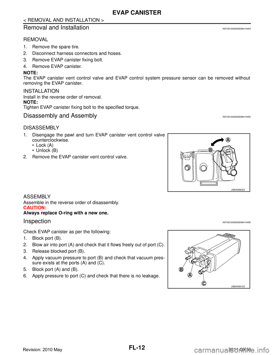
1. Disengage the pawl and turn EVAP canister vent control valve counterclockwise.
Lock (A)
Unlock (B)
2. Remove the EVAP canister vent control valve.
ASSEMBLY
Assemble in the reverse order of disassembly.
CAUTION:
Always replace O-ring with a new one.
InspectionINFOID:0000000006414456
Check EVAP canister as per the following:
1. Block port (B).
2. Blow air into port (A) and check that it flows freely out of port (C).
3. Release blocked port (B).
4. Apply vacuum pressure to port (B) and check that vacuum pres- sure exists at the ports (A) and (C).
5. Block port (A) and (B).
6. Apply pressure to port (C) and check that there is no leakage.
JSBIA0690ZZ
JSBIA0691ZZ
Revision: 2010 May2011 QX56
Page 2946 of 5598

FSU-4
< PREPARATION >
PREPARATION
PREPARATION
PREPARATION
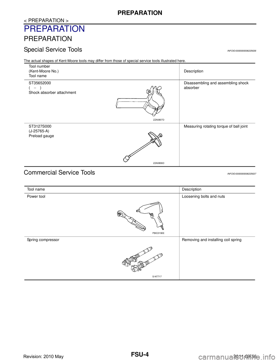
Special Service ToolsINFOID:0000000006225636
The actual shapes of Kent-Moore tools may differ from those of special service tools illustrated here.
Commercial Service ToolsINFOID:0000000006225637
Tool number
(Kent-Moore No.)
Tool name Description
ST35652000
( − )
Shock absorber attachment Disassembling and assembling shock
absorber
ST3127S000
(J-25765-A)
Preload gauge Measuring rotating torque of ball joint
ZZA0807D
ZZA0806D
Tool name
Description
Power tool Loosening bolts and nuts
Spring compressor Removing and installing coil spring
PBIC0190E
S-NT717
Revision: 2010 May2011 QX56
Page 2954 of 5598

FSU-12
< REMOVAL AND INSTALLATION >
FRONT COIL SPRING AND SHOCK ABSORBER
When installing the shock absorber attachment to shock absorber, wrap a shop cloth around
shock absorber to protect it from damage.
2. Compress coil spring using a spring compressor (commercial service tool), and install it onto shock absorber.
CAUTION:
Be sure a spring compressor is securely attach ed to coil spring. Compress coil spring.
Set coil spring so that its paint marks face downward.
3. Apply soapy water to dust cover. CAUTION:
Never use machine oil.
4. Install dust cover, bound bumper cover, rubber seat , bushings, tube, shock absorber mounting bracket,
and washer to shock absorber.
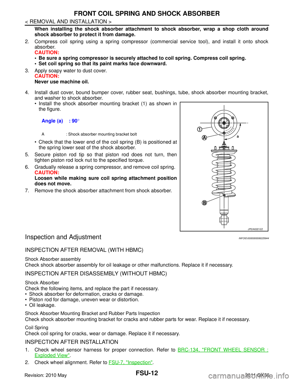
Install the shock absorber mounting bracket (1) as shown in the figure.
Check that the lower end of the coil spring (B) is positioned at the spring lower seat of the shock absorber.
5. Secure piston rod tip so that piston rod does not turn, then tighten piston rod lock nut to the specified torque.
6. Gradually release a spring compressor, and remove coil spring. CAUTION:
Loosen while making sure co il spring attachment position
does not move.
7. Remove the shock absorber attachment from shock absorber.
Inspection and AdjustmentINFOID:0000000006225644
INSPECTION AFTER REMOVAL (WITH HBMC)
Shock Absorber assembly
Check shock absorber assembly for oil leakage or other malfunctions. Replace it if necessary.
INSPECTION AFTER DISASSEMBLY (WITHOUT HBMC)
Shock Absorber
Check the following items, and replace the part if necessary.
Shock absorber for deformation, cracks or damage.
Piston rod for damage, uneven wear or distortion.
Oil leakage.
Shock Absorber Mounting Bracket and Rubber Parts Inspection
Check shock absorber mounting bracket for cracks and rubber parts for wear. Replace it if necessary.
Coil Spring
Check coil spring for cracks, wear or damage. Replace it if necessary.
INSPECTION AFTER INSTALLATION
1. Check wheel sensor harness for proper connection. Refer to BRC-134, "FRONT WHEEL SENSOR :
Exploded View".
2. Check wheel alignment. Refer to FSU-7, "
Inspection".
Angle (a) : 90
°
A : Shock absorber mounting bracket bolt
JPEIA0221ZZ
Revision: 2010 May2011 QX56