2011 INFINITI QX56 torque
[x] Cancel search: torquePage 2641 of 5598

CAMSHAFTEM-79
< REMOVAL AND INSTALLATION >
C
DE
F
G H
I
J
K L
M A
EM
NP
O
1. Put V-block on precise flat table, and support No. 2 and 5 jour-
nals of camshaft.
CAUTION:
Never support No. 1 journal (on the side of camshaft
sprocket) because it has a different diameter from the other
four locations.
2. Set a dial indicator vertically to No. 3 journal.
3. Turn exhaust camshaft to one direction with hands, and mea- sure the camshaft runout on a dial indicator. (Total indicator
reading)
4. If it exceeds the limit, replace exhaust camshaft.
Exhaust Camshaft Cam Height
Measure the exhaust camshaft cam height with a micrometer.
If wear exceeds the limit, replace exhaust camshaft.
Exhaust Camshaft Journal Oil Clearance
EXHAUST CAMSHAFT JOURNAL DIAMETER
Measure the outer diameter of exhaust camshaft journal with a micrometer (A).
VVEL LADDER ASSEMBLY (EXH SIDE) INNER DIAMETER Tighten VVEL ladder assembly bolts to the specifi ed torque. Refer to “ASSEMBLY” for the tightening proce-
dure.
Measure inner diameter (A) of VVEL ladder assembly (exhaust side) with a bore gauge.
EXHAUST CAMSHAFT JOURNAL OIL CLEARANCE
Standard and limit
: Refer to EM-133, "
Camshaft".
PBIC0929E
Standard and limit
: Refer to EM-133, "
Camshaft".
EMQ0072D
Standard : Refer to EM-133, "Camshaft".
JPBIA0122ZZ
Standard : Refer to EM-133, "Camshaft".
PBIC1645E
Revision: 2010 May2011 QX56
Page 2666 of 5598
EM-104
< UNIT DISASSEMBLY AND ASSEMBLY >
ENGINE STAND SETTING
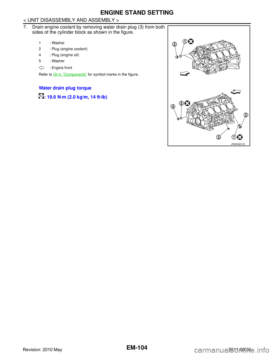
7. Drain engine coolant by removing water drain plug (3) from bothsides of the cylinder block as shown in the figure.
1: Washer
2 : Plug (engine coolant)
4 : Plug (engine oil)
5: Washer
: Engine front
Refer to GI-4, "
Components" for symbol marks in the figure.
Water drain plug torque
: 19.6 N·m (2.0 kg/m, 14 ft-lb)
JPBIA3501ZZ
Revision: 2010 May2011 QX56
Page 2672 of 5598
EM-110
< UNIT DISASSEMBLY AND ASSEMBLY >
CYLINDER BLOCK
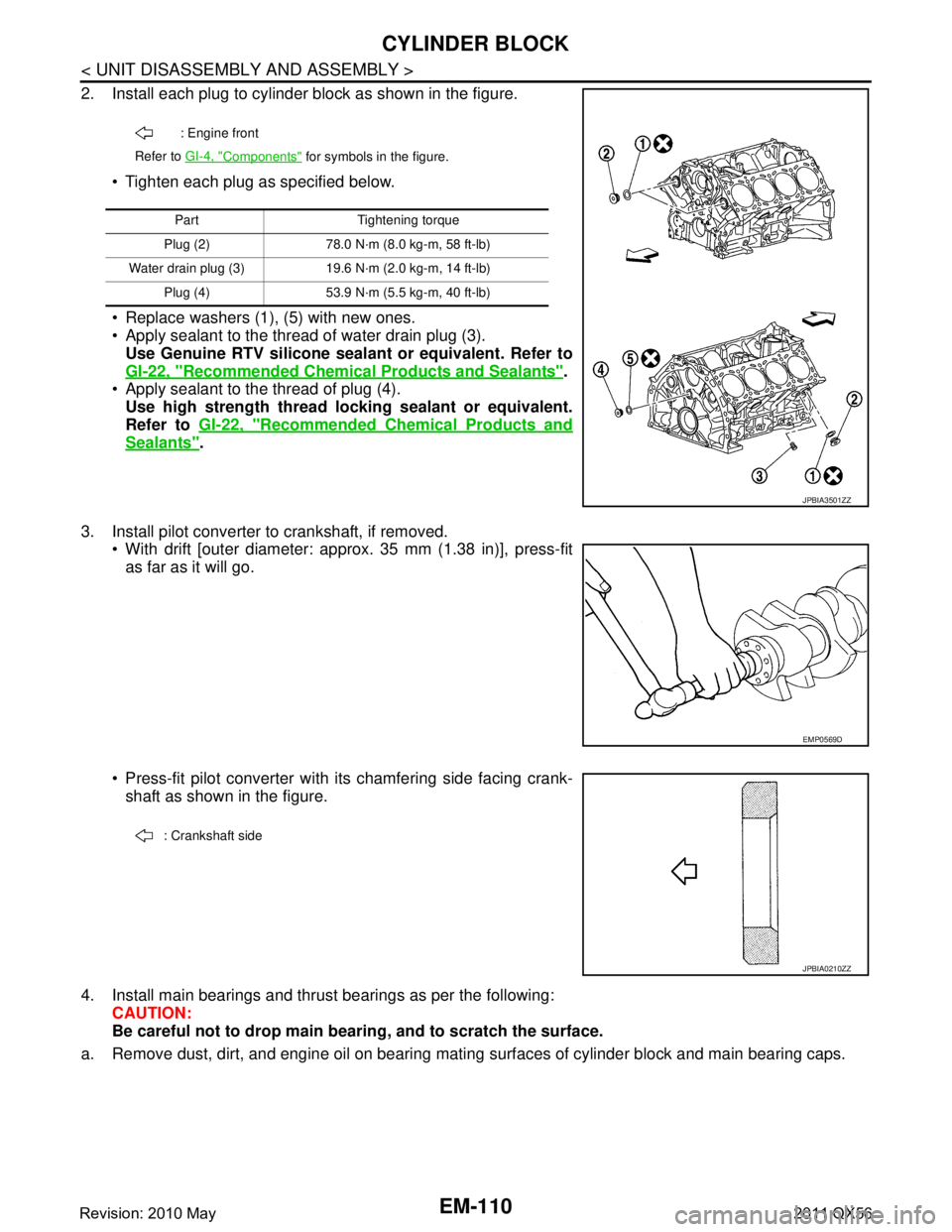
2. Install each plug to cylinder block as shown in the figure. Tighten each plug as specified below.
Replace washers (1), (5) with new ones.
Apply sealant to the thread of water drain plug (3).Use Genuine RTV silicone seal ant or equivalent. Refer to
GI-22, "
Recommended Chemical Pr oducts and Sealants".
Apply sealant to the thread of plug (4). Use high strength thread lo cking sealant or equivalent.
Refer to GI-22, "
Recommended Chemical Products and
Sealants".
3. Install pilot converter to crankshaft, if removed. With drift [outer diameter: appr ox. 35 mm (1.38 in)], press-fit
as far as it will go.
Press-fit pilot converter with its chamfering side facing crank- shaft as shown in the figure.
4. Install main bearings and thrust bearings as per the following: CAUTION:
Be careful not to drop main b earing, and to scratch the surface.
a. Remove dust, dirt, and engine oil on bearing mating surfaces of cylinder block and main bearing caps.
: Engine front
Refer to GI-4, "
Components" for symbols in the figure.
Part Tightening torque
Plug (2) 78.0 N·m (8.0 kg-m, 58 ft-lb)
Water drain plug (3) 19.6 N·m (2.0 kg-m, 14 ft-lb) Plug (4) 53.9 N·m (5.5 kg-m, 40 ft-lb)
JPBIA3501ZZ
EMP0569D
: Crankshaft side
JPBIA0210ZZ
Revision: 2010 May2011 QX56
Page 2680 of 5598
EM-118
< UNIT DISASSEMBLY AND ASSEMBLY >
CYLINDER BLOCK
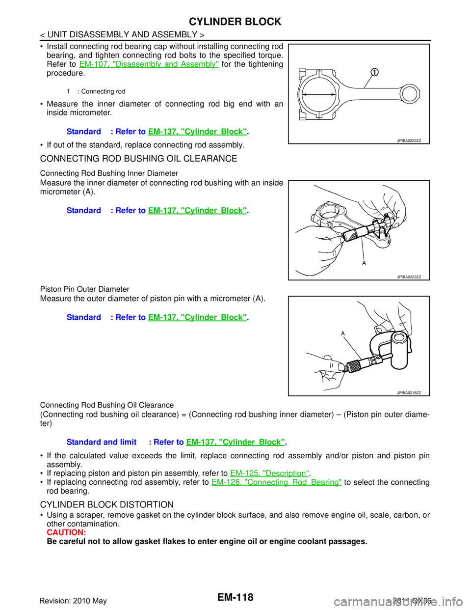
Install connecting rod bearing cap without installing connecting rodbearing, and tighten connecting rod bolts to the specified torque.
Refer to EM-107, "
Disassembly and Assembly" for the tightening
procedure.
Measure the inner diameter of connecting rod big end with an inside micrometer.
If out of the standard, replace connecting rod assembly.
CONNECTING ROD BUSHING OIL CLEARANCE
Connecting Rod Bushing Inner Diameter
Measure the inner diameter of connecting rod bushing with an inside
micrometer (A).
Piston Pin Outer Diameter
Measure the outer diameter of piston pin with a micrometer (A).
Connecting Rod Bushing Oil Clearance
(Connecting rod bushing oil clearance) = (Connecting rod bus hing inner diameter) – (Piston pin outer diame-
ter)
If the calculated value exceeds the limit, replac e connecting rod assembly and/or piston and piston pin
assembly.
If replacing piston and piston pin assembly, refer to EM-125, "
Description".
If replacing connecting rod assembly, refer to EM-126, "
ConnectingRodBearing" to select the connecting
rod bearing.
CYLINDER BLOCK DISTORTION
Using a scraper, remove gasket on the cylinder block su rface, and also remove engine oil, scale, carbon, or
other contamination.
CAUTION:
Be careful not to allow gasket flakes to en ter engine oil or engine coolant passages.
1 : Connecting rod
Standard : Refer to EM-137, "CylinderBlock".
JPBIA0222ZZ
Standard : Refer to EM-137, "CylinderBlock".
JPBIA0223ZZ
Standard : Refer to EM-137, "CylinderBlock".
JPBIA0218ZZ
Standard and limit : Refer to EM-137, "CylinderBlock".
Revision: 2010 May2011 QX56
Page 2681 of 5598
CYLINDER BLOCKEM-119
< UNIT DISASSEMBLY AND ASSEMBLY >
C
DE
F
G H
I
J
K L
M A
EM
NP
O
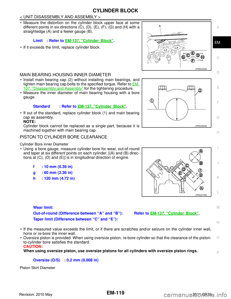
Measure the distortion on the cylinder block upper face at some
different points in six directions (C ), (D), (E), (F), (G) and (H) with a
straightedge (A) and a feeler gauge (B).
If it exceeds the limit, replace cylinder block.
MAIN BEARING HOUSING INNER DIAMETER
Install main bearing cap (2) without installing main bearings, and tighten main bearing cap bolts to the specified torque. Refer to EM-
107, "Disassembly and Assembly" for the tightening procedure.
Measure the inner diameter of main bearing housing with a bore
gauge.
If out of the standard, replace cylinder block (1) and main bearing cap as assembly.
NOTE:
Cylinder block cannot be replaced as a single part, because it is
machined together with main bearing cap.
PISTON TO CYLINDER BORE CLEARANCE
Cylinder Bore inner Diameter
Using a bore gauge, measure cylinder bore for wear, out-of-round
and taper at six different points on each cylinder. [(A) and (B) direc-
tions at (C), (D) and (E)] is in longitudinal direction of engine.
If the measured value exceeds the limit, or if there are scratches and/or seizure on the cylinder inner wall,
hone or re-bore the inner wall.
Oversize piston is provided. When using oversize piston, re-bore cylinder so that the clearance of the piston-
to-cylinder bore satisfies the standard.
CAUTION:
When using oversize pist on, use oversize pistons for all cyl inders with oversize piston rings.
Piston Skirt Diameter
Limit : Refer to EM-137, "CylinderBlock".
JPBIA0224ZZ
Standard : Refer to EM-137, "CylinderBlock".
JPBIA0225ZZ
f : 10 mm (0.39 in)
g : 60 mm (2.36 in)
h : 120 mm (4.72 in)
JPBIA2279ZZ
Wear limit:
Refer to EM-137, "
CylinderBlock".
Out-of-round (Difference between “A” and “B”):
Taper limit (Difference between “C” and “E”):
Oversize (O/S) : 0.2 mm (0.008 in)
Revision: 2010 May2011 QX56
Page 2682 of 5598
EM-120
< UNIT DISASSEMBLY AND ASSEMBLY >
CYLINDER BLOCK
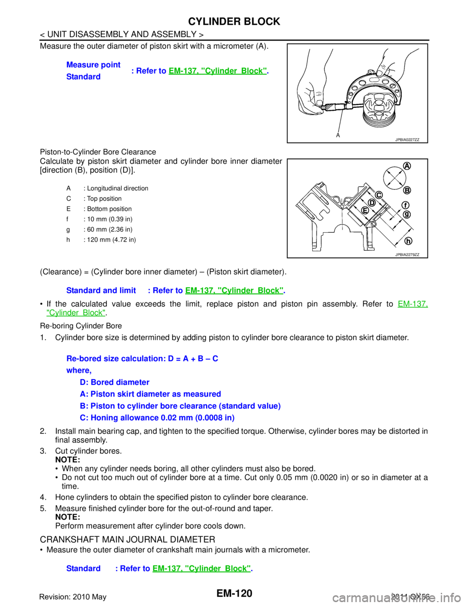
Measure the outer diameter of piston skirt with a micrometer (A).
Piston-to-Cylinder Bore Clearance
Calculate by piston skirt diameter and cylinder bore inner diameter
[direction (B), position (D)].
(Clearance) = (Cylinder bore inner diameter) – (Piston skirt diameter).
If the calculated value exceeds the limit, r eplace piston and piston pin assembly. Refer to EM-137,
"CylinderBlock".
Re-boring Cylinder Bore
1. Cylinder bore size is determined by adding piston to cylinder bore clearance to piston skirt diameter.
2. Install main bearing cap, and tighten to the specifi ed torque. Otherwise, cylinder bores may be distorted in
final assembly.
3. Cut cylinder bores. NOTE:
When any cylinder needs boring, all other cylinders must also be bored.
Do not cut too much out of cylinder bore at a time. Cut only 0.05 mm (0.0020 in) or so in diameter at a
time.
4. Hone cylinders to obtain the specified piston to cylinder bore clearance.
5. Measure finished cylinder bore for the out-of-round and taper. NOTE:
Perform measurement after cylinder bore cools down.
CRANKSHAFT MAIN JOURNAL DIAMETER
Measure the outer diameter of cranks haft main journals with a micrometer.
Measure point
: Refer to EM-137, "
CylinderBlock".
Standard
JPBIA0227ZZ
A : Longitudinal direction
C : Top position
E : Bottom position
f : 10 mm (0.39 in)
g : 60 mm (2.36 in)
h : 120 mm (4.72 in)
JPBIA2279ZZ
Standard and limit : Refer to EM-137, "CylinderBlock".
Re-bored size calculation: D = A + B – C
where, D: Bored diameter
A: Piston skirt diameter as measured
B: Piston to cylinder bore clearance (standard value)
C: Honing allowance 0.02 mm (0.0008 in)
Standard : Refer to EM-137, "
CylinderBlock".
Revision: 2010 May2011 QX56
Page 2684 of 5598
EM-122
< UNIT DISASSEMBLY AND ASSEMBLY >
CYLINDER BLOCK
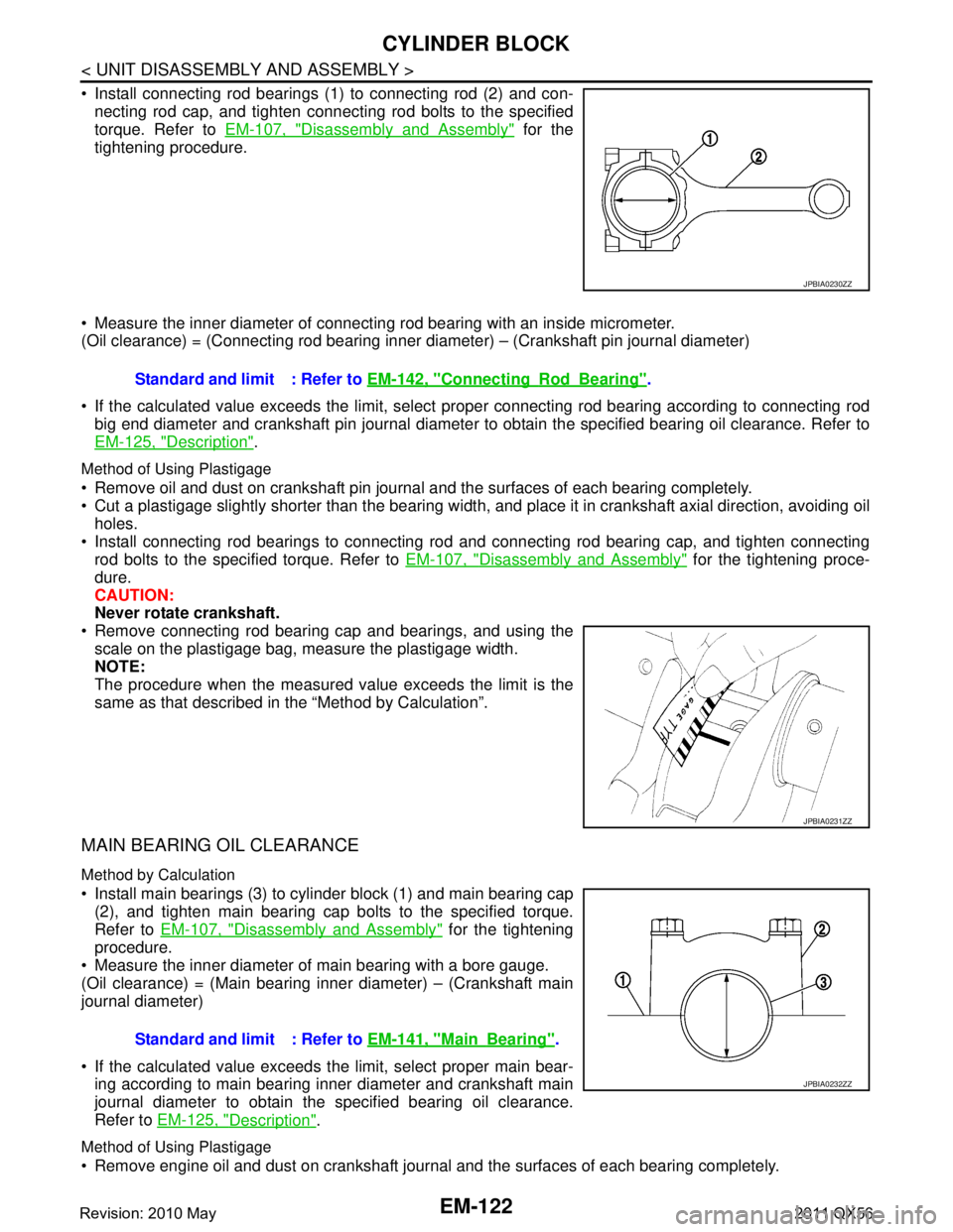
Install connecting rod bearings (1) to connecting rod (2) and con-necting rod cap, and tighten connecting rod bolts to the specified
torque. Refer to EM-107, "
Disassembly and Assembly" for the
tightening procedure.
Measure the inner diameter of connecting rod bearing with an inside micrometer.
(Oil clearance) = (Connecting rod bearing inner di ameter) – (Crankshaft pin journal diameter)
If the calculated value exceeds the limit, select proper connecting rod bearing according to connecting rod
big end diameter and crankshaft pin journal diameter to obtain the specified bearing oil clearance. Refer to
EM-125, "
Description".
Method of Using Plastigage
Remove oil and dust on crankshaft pin journal and the surfaces of each bearing completely.
Cut a plastigage slightly shorter than the bearing width, and place it in crankshaft axial direction, avoiding oil
holes.
Install connecting rod bearings to connecting rod and connecting rod bearing cap, and tighten connecting
rod bolts to the specified torque. Refer to EM-107, "
Disassembly and Assembly" for the tightening proce-
dure.
CAUTION:
Never rotate crankshaft.
Remove connecting rod bearing cap and bearings, and using the
scale on the plastigage bag, measure the plastigage width.
NOTE:
The procedure when the measured va lue exceeds the limit is the
same as that described in the “Method by Calculation”.
MAIN BEARING OIL CLEARANCE
Method by Calculation
Install main bearings (3) to cylinder block (1) and main bearing cap (2), and tighten main bearing cap bolts to the specified torque.
Refer to EM-107, "
Disassembly and Assembly" for the tightening
procedure.
Measure the inner diameter of main bearing with a bore gauge.
(Oil clearance) = (Main bearing inner diameter) – (Crankshaft main
journal diameter)
If the calculated value exceeds t he limit, select proper main bear-
ing according to main bearing inner diameter and crankshaft main
journal diameter to obtain the specified bearing oil clearance.
Refer to EM-125, "
Description".
Method of Using Plastigage
Remove engine oil and dust on crankshaft journal and the surfaces of each bearing completely.
JPBIA0230ZZ
Standard and limit : Refer to EM-142, "ConnectingRodBearing".
JPBIA0231ZZ
Standard and limit : Refer to EM-141, "MainBearing".
JPBIA0232ZZ
Revision: 2010 May2011 QX56
Page 2685 of 5598
CYLINDER BLOCKEM-123
< UNIT DISASSEMBLY AND ASSEMBLY >
C
DE
F
G H
I
J
K L
M A
EM
NP
O
Cut a plastigage slightly shorter than the bearing width,
and place it in crankshaft axial direction, avoiding oil
holes.
Install main bearing to cylinder block and main bearing cap, and tighten main bearing cap bolts with main
bearing cap to the specified torque. Refer to EM-107, "
Disassembly and Assembly" for the tightening proce-
dure.
CAUTION:
Never rotate crankshaft.
Remove main bearing cap and bearings, and using the scale on the plastigage bag, measure the plastigage width.
NOTE:
The procedure when the measured value exceeds the limit is the
same as that described in the “Method by Calculation”.
MAIN BEARING CRUSH HEIGHT
When main bearing cap is removed after being tightened to thespecified torque with main bearings (1) installed, the tip end of
bearing must protrude. Refer to EM-107, "
Disassembly and
Assembly" for the tightening procedure.
If the standard is not met, replace main bearings.
CONNECTING ROD BEARING CRUSH HEIGHT
When connecting rod bearing cap is removed after being tightened to the specified torque with connecting rod bearings (1) installed,
the tip end of bearing must protrude. Refer to EM-107, "
Disassem-
bly and Assembly" for the tightening procedure.
If the standard is not met, replace connecting rod bearings.
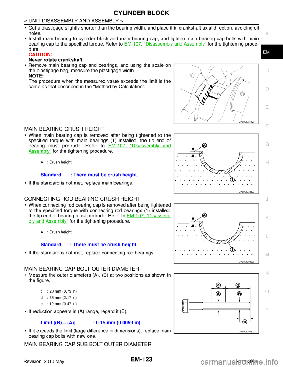
MAIN BEARING CAP BOLT OUTER DIAMETER
Measure the outer diameters (A), (B) at two positions as shown in
the figure.
If reduction appears in (A) range, regard it (B).
If it exceeds the limit (large difference in dimensions), replace main bearing cap bolts with new one.
MAIN BEARING CAP SUB BOLT OUTER DIAMETER
JPBIA0231ZZ
A : Crush height
Standard : There must be crush height.
JPBIA0233ZZ
A : Crush height
Standard : There must be crush height.
JPBIA0233ZZ
c : 20 mm (0.79 in)
d : 55 mm (2.17 in)
e : 12 mm (0.47 in)
Limit [(B) – (A)] : 0.15 mm (0.0059 in)
JPBIA2280ZZ
Revision: 2010 May2011 QX56