2011 INFINITI QX56 torque
[x] Cancel search: torquePage 2983 of 5598

TIGHTENING TORQUE OF STANDARD BOLTSGI-19
< HOW TO USE THIS MANUAL >
C
DE
F
G H
I
J
K L
M B
GI
N
O PTIGHTENING TORQUE OF STANDARD BOLTS
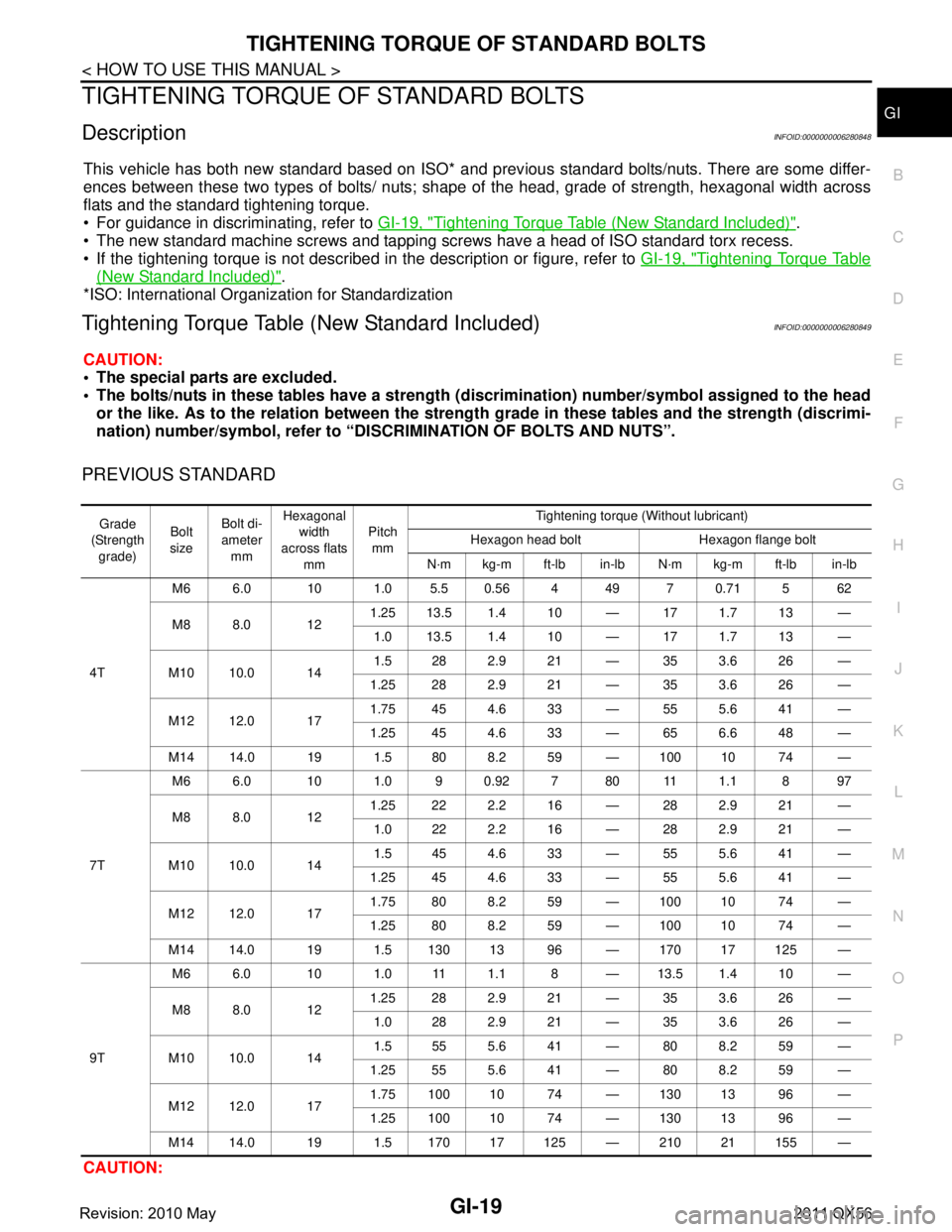
DescriptionINFOID:0000000006280848
This vehicle has both new standard based on ISO* and prev ious standard bolts/nuts. There are some differ-
ences between these two types of bolts/ nuts; shape of the head, grade of strength, hexagonal width across
flats and the standard tightening torque.
For guidance in discriminating, refer to GI-19, "
Tightening Torque Table (New Standard Included)".
The new standard machine screws and tapping screws have a head of ISO standard torx recess.
If the tightening torque is not described in the description or figure, refer to GI-19, "
Tightening Torque Table
(New Standard Included)".
*ISO: International Organization for Standardization
Tightening Torque Table (New Standard Included)INFOID:0000000006280849
CAUTION:
The special parts are excluded.
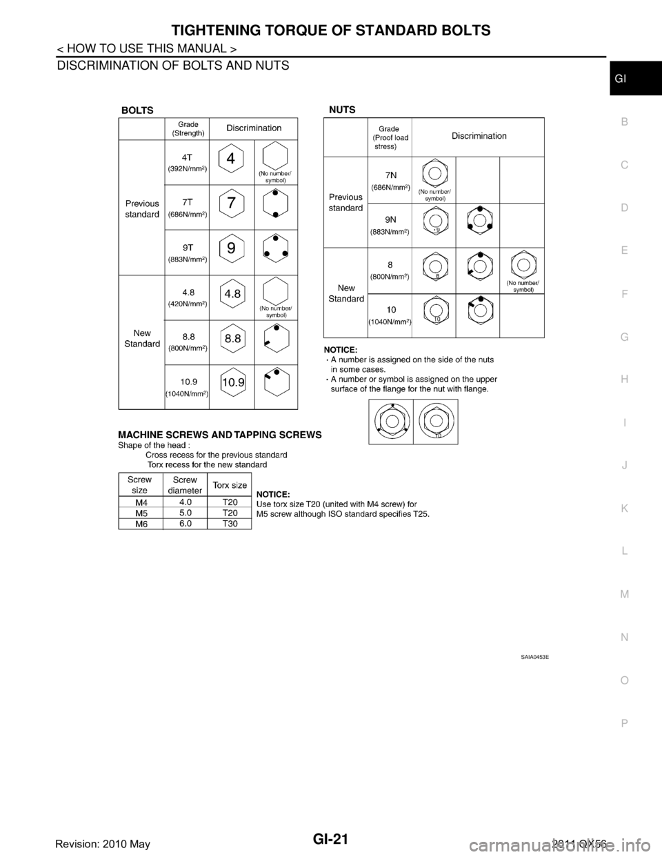
The bolts/nuts in these tables have a strength (d iscrimination) number/symbol assigned to the head
or the like. As to the relation between the streng th grade in these tables and the strength (discrimi-
nation) number/symbol, refer to “DISCRIMINATION OF BOLTS AND NUTS”.
PREVIOUS STANDARD
CAUTION:
Grade
(Strength grade) Bolt
size Bolt di-
ameter
mm Hexagonal
width
across flats
mm Pitch
mm Tightening torque (Without lubricant)
Hexagon head bolt Hexagon flange bolt
N·m kg-m ft-lb in-lb N·m kg-m ft-lb in-lb
4T M6 6.0 10 1.05.50.564 49 70.715 62
M8 8.0 12
1.25 13.5 1.4 10 — 17 1.7 13 —
1.0 13.5 1.4 10 — 17 1.7 13 —
M10 10.0 14 1.5282.921 — 353.626 —
1.25 28 2.9 21 — 35 3.6 26 —
M12 12.0 17 1.75 45 4.6 33 — 55 5.6 41 —
1.25 45 4.6 33 — 65 6.6 48 —
M14 14.0 19 1.5 80 8.2 59 — 100 10 74 —
7T M6 6.0 10 1.0 9 0.92 7 80 11 1.1 8 97
M8 8.0 12
1.25 22 2.2 16 — 28 2.9 21 —
1.0222.216 — 282.921 —
M10 10.0 14 1.5454.633 — 555.641 —
1.25 45 4.6 33 — 55 5.6 41 —
M12 12.0 17 1.75 80 8.2 59 — 100 10 74 —
1.25 80 8.2 59 — 100 10 74 —
M1414.0 19 1.513013 96 — 17017125 —
9T M6 6.0 10 1.0 11 1.1 8 — 13.5 1.4 10 —
M8 8.0 12
1.25 28 2.9 21 — 35 3.6 26 —
1.0282.921 — 353.626 —
M10 10.0 14 1.5555.641 — 808.259 —
1.25 55 5.6 41 — 80 8.2 59 —
M12 12.0 17 1.75 100 10 74 — 130 13 96 —
1.25 100 10 74 — 130 13 96 —
M14 14.0 19 1.5 170 17 125 — 210 21 155 —
Revision: 2010 May2011 QX56
Page 2984 of 5598

GI-20
< HOW TO USE THIS MANUAL >
TIGHTENING TORQUE OF STANDARD BOLTS
The parts with aluminum or the cast iron washer surface/thread surface are excluded.
NEW STANDARD BASED ON ISO
CAUTION:
1. Use tightening torque with lubricant for the new standard bolts/nuts in principle. Friction coeffi-
cient stabilizer is applied to the new standard bolts/nuts.
2. However, use tightening to rque without lubricant for the foll owing cases. Friction coefficient stabi-
lizer is not applied to the following bolts/nuts.
- Grade 4.8, M6 size bolt, Co nical spring washer installed
- Paint removing nut (Size M6 an d M8) for fixing with weld bolt
Grade
(Strength grade) Bolt
size Bolt di-
ameter
mm Hexagonal
width
across flats mm Pitch
mm Tightening torque
Hexagon head bolt Hexagon flange bolt
N·m kg-m ft-lb in-lb N·m kg-m ft-lb in-lb
4.8
(Without
lubricant) M6 6.0 10 1.0 5.5 0.56 4 49 7 0.71 5 62
M8 8.0 13
1.25 13.5 1.4 10 — 17 1.7 13 —
1.0 13.5 1.4 10 — 17 1.7 13 —
M10 10.0 16 1.5 282.921 — 353.626 —
1.25 28 2.9 21 — 35 3.6 26 —
M12 12.0 18 1.75 45 4.6 33 — 55 5.6 41 —
1.25 45 4.6 33 — 65 6.6 48 —
M14 14.0 21 1.5 80 8.2 59 — 100 10 74 —
4.8
(With lu-
bricant) M6 6.0 10 1.0 4 0.41 3 35 5.5 0.56 4 49
M8 8.0 13
1.25 11 1.1 8 — 13.5 1.4 10 —
1.0 11 1.1 8 — 13.5 1.4 10 —
M10 10.0 16 1.5 222.216 — 282.921 —
1.25 22 2.2 16 — 28 2.9 21 —
M12 12.0 18 1.75 35 3.6 26 — 45 4.6 33 —
1.25 35 3.6 26 — 45 4.6 33 —
M14 14.0 21 1.5 65 6.6 48 — 80 8.2 59 —
8.8
(With lu-
bricant) M6 6.0 10 1.0 8 0.82 6 71 10 1.0 7 89
M8 8.0 13
1.25 21 2.1 15 — 25 2.6 18 —
1.0 212.115 — 252.618 —
M10 10.0 16 1.5 404.130 — 505.137 —
1.25 40 4.1 30 — 50 5.1 37 —
M12 12.0 18 1.75 70 7.1 52 — 85 8.7 63 —
1.25 70 7.1 52 — 85 8.7 63 —
M14 14.0 21 1.5 120 12 89 — 140 14 103 —
10.9
(With lu-
bricant) M6 6.0 10 1.0 10 1.0 7 89 12 1.2 9 106
M8 8.0 13
1.25 27 2.8 20 — 32 3.3 24 —
1.0 272.820 — 323.324 —
M10 10.0 16 1.5 555.641 — 656.648 —
1.25 55 5.6 41 — 65 6.6 48 —
M12 12.0 18 1.75 95 9.7 70 — 110 11 81 —
1.25 95 9.7 70 — 110 11 81 —
M14 14.0 21 1.5 160 16 118 — 180 18 133 —
Revision: 2010 May2011 QX56
Page 2985 of 5598

TIGHTENING TORQUE OF STANDARD BOLTSGI-21
< HOW TO USE THIS MANUAL >
C
DE
F
G H
I
J
K L
M B
GI
N
O P
DISCRIMINATION OF BOLTS AND NUTS
SAIA0453E
Revision: 2010 May2011 QX56
Page 3061 of 5598

PRECAUTIONSHA-5
< PRECAUTION >
C
DE
F
G H
J
K L
M A
B
HA
N
O P
- Never allow lubricant (A/C System Oil Type R) to come in contact with styrene foam parts. Damage
may result.
REFRIGERANT CONNECTION
A new type refrigerant connection has been introduced to a ll refrigerant lines except the following location.
Expansion valve to evaporator
Refrigerant pressure sensor to liquid tank
WARNING:
Check that all refrigerant is discharged into the recycling equipment and the pressure in the system is
less than atmospheric pressure. Then gradually loo sen the discharge side hose fitting and remove it.
CAUTION:
Observe the following when replacing or cleaning refrigerant cycle components.
Store it in the same way at it is when mounted on the car when the compressor is removed. Failure
to do so will cause lubricant to enter the low-pressure chamber.
Use always a torque wrench and a b ack-up wrench when connecting tubes.
Plug immediately all openings to prevent entry of dust and mois ture after disconnecting tubes.
Connect the pipes at the final stag e of the operation when installing an air conditioner in the vehicle.
Never remove the seal caps of pipes and other compon ents until just before required for connection.
Allow components stored in cool areas to warm to working area temperature before removing seal
caps. This prevents condensation from forming inside A/C components.
Remove thoroughly moisture from the refriger ation system before charging the refrigerant.
Replace always used O-rings.
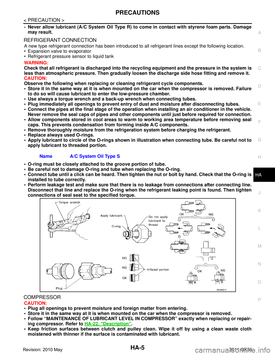
Apply lubricant to circle of th e O-rings shown in illustration when connecting tube. Be careful not to
apply lubricant to threaded portion.
O-ring must be closely attached to the groove portion of tube.
Be careful not to damage O-ring and tube when replacing the O-ring.
Connect tube until a click can be heard. Then tighten the nut or bolt by hand. Check that the O-ring is
installed to tube correctly.
Perform leakage test and make sure that there is no leakage from connections after connecting line.
Disconnect that line and replace the O-ring when the refrigerant leaking point is found. Then tighten
connections of seal seat to the specified torque.
COMPRESSOR
CAUTION:
Plug all openings to prevent moisture and foreign matter from entering.
Store it in the same way at it is when moun ted on the car when the compressor is removed.
Follow “MAINTENANCE OF LUBRICANT LEVEL IN CO MPRESSOR” exactly when replacing or repair-
ing compressor. Refer to HA-22, "
Description".
Keep friction surfaces between clutch and pulley cl ean. Wipe it off by using a clean waste cloth
moistened with thinner if the surface is contaminated with lubricant.
Name A/C System Oil Type S
RHA861F
Revision: 2010 May2011 QX56
Page 3088 of 5598

HA-32
< REMOVAL AND INSTALLATION >
COMPRESSOR
2. Remove center bolt, and then remove clutch disc.
3. Remove snap ring using external snap ring pliers.
4. Position center pulley puller on the end of the drive shaft, and remove pulley assembly using any commer-
cially available pulley puller.
To prevent pulley groove from being deformed, pulle r claws should be positioned into the edge of the pul-
ley assembly.
5. Disconnect field coil harness from compressor unit.
6. Remove screws, and then remove field coil.
INSTALLATION
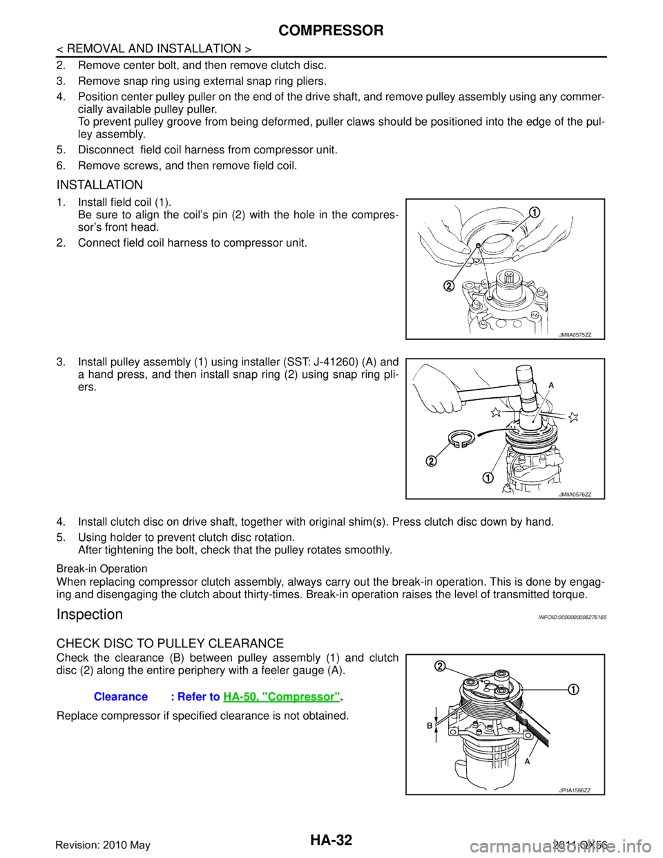
1. Install field coil (1). Be sure to align the coil’s pin (2) with the hole in the compres-
sor’s front head.
2. Connect field coil harness to compressor unit.
3. Install pulley assembly (1) using installer (SST: J-41260) (A) and a hand press, and then install snap ring (2) using snap ring pli-
ers.
4. Install clutch disc on drive shaft, together with original shim(s). Press clutch disc down by hand.
5. Using holder to prevent clutch disc rotation. After tightening the bolt, check that the pulley rotates smoothly.
Break-in Operation
When replacing compressor clutch assembly, always carry out the break-in operation. This is done by engag-
ing and disengaging the clutch about thirty-times. Break-i n operation raises the level of transmitted torque.
InspectionINFOID:0000000006276165
CHECK DISC TO PULLEY CLEARANCE
Check the clearance (B) between pulley assembly (1) and clutch
disc (2) along the entire periphery with a feeler gauge (A).
Replace compressor if specified clearance is not obtained.
JMIIA0575ZZ
JMIIA0576ZZ
Clearance : Refer to HA-50, "Compressor".
JPIIA1566ZZ
Revision: 2010 May2011 QX56
Page 3393 of 5598

PRECAUTIONSIP-3
< PRECAUTION >
C
DE
F
G H
I
K L
M A
B
IP
N
O P
5. When the repair work is completed, re-connect both battery cables. With the brake pedal released, turn
the push-button ignition switch from ACC position to ON position, then to LOCK position. (The steering
wheel will lock when the push-button ignition switch is turned to LOCK position.)
6. Perform self-diagnosis check of a ll control units using CONSULT-III.
ServiceINFOID:0000000006113090
Disconnect battery negative terminal in advance.
Disconnect air bag system line in advance.
Never tamper with or force air bag lid open, as this may adversely affect air bag performance.
Be careful not to scratch pad and other parts.
When removing or disassembling any part, be careful not to damage or deform it. Protect parts, that may get
in the way with a shop cloth.
When removing parts with a screwdriver or other tool, cover the tool surface with vinyl tape to protect parts.
Keep removed parts protected with a shop cloth.
If a clip is deformed or damaged, replace it.
If an unreusable part is removed, replace it with a new one.
Tighten bolts and nuts firmly to the specified torque.
After reassembly is complete, check that each part functions correctly.
Remove stains via the following procedure.
Water-soluble stains:
Dip a soft cloth in warm water, and then squeeze it tightly. After wiping off the stain, wipe with a soft dry cloth.
Oil stain:
Dissolve a synthetic detergent in warm water (density of 2 to 3%), dip the cloth, then wipe off the stain with the
cloth. Next, dip the cloth in fresh water and squeeze it tightly. Then wipe off the detergent completely. Then
wipe the area with a soft dry cloth.
Never use any organic solvent, such as thinner or benzine.
Revision: 2010 May2011 QX56
Page 3432 of 5598
![INFINITI QX56 2011 Factory Service Manual
LAN-12
< SYSTEM DESCRIPTION >[CAN FUNDAMENTAL]
TROUBLE DIAGNOSIS
Example: TCM branch line open circuit
Example: Data link connector branch line open circuit
SKIB8738E
Unit name Major symptom
ECM Engi INFINITI QX56 2011 Factory Service Manual
LAN-12
< SYSTEM DESCRIPTION >[CAN FUNDAMENTAL]
TROUBLE DIAGNOSIS
Example: TCM branch line open circuit
Example: Data link connector branch line open circuit
SKIB8738E
Unit name Major symptom
ECM Engi](/manual-img/42/57033/w960_57033-3431.png)
LAN-12
< SYSTEM DESCRIPTION >[CAN FUNDAMENTAL]
TROUBLE DIAGNOSIS
Example: TCM branch line open circuit
Example: Data link connector branch line open circuit
SKIB8738E
Unit name Major symptom
ECM Engine torque limiting is affected, and shift harshness increases.
BCM Reverse warning chime does not sound.
EPS control unit No rmal operation.
Combination meter Shift position indicator and OD OFF indicator turn OFF.
Warning lamps turn ON.
ABS actuator and electric unit (control unit) Normal operation.
TCM No impact on operation.
IPDM E/R Normal operation.
SKIB8739E
Revision: 2010 May2011 QX56
Page 3433 of 5598
![INFINITI QX56 2011 Factory Service Manual
LAN
TROUBLE DIAGNOSISLAN-13
< SYSTEM DESCRIPTION > [CAN FUNDAMENTAL]
C
D
E
F
G H
I
J
K L
B A
O P
N
NOTE:
When data link connector branch line is open, transmi
ssion and reception of CAN communicati INFINITI QX56 2011 Factory Service Manual
LAN
TROUBLE DIAGNOSISLAN-13
< SYSTEM DESCRIPTION > [CAN FUNDAMENTAL]
C
D
E
F
G H
I
J
K L
B A
O P
N
NOTE:
When data link connector branch line is open, transmi
ssion and reception of CAN communicati](/manual-img/42/57033/w960_57033-3432.png)
LAN
TROUBLE DIAGNOSISLAN-13
< SYSTEM DESCRIPTION > [CAN FUNDAMENTAL]
C
D
E
F
G H
I
J
K L
B A
O P
N
NOTE:
When data link connector branch line is open, transmi
ssion and reception of CAN communication signals
are not affected. Therefore, no symptoms occur. However, be sure to repair malfunctioning circuit.
The model (all units on CAN communication system are Diag on CAN) cannot perform CAN diagnosis with
CONSULT-III if the following error occurs. The error is judged by the symptom.
Example: Main Line Between Data Link Connector and ABS Actuator and Electr ic Unit (Control Unit) Open Circuit
Unit name Major symptom
ECM
Normal operation.
BCM
EPS control unit
Combination meter
ABS actuator and electric
unit (control unit)
TCM
IPDM E/R
Error Difference of symptom
Data link connector branch line open circuit Normal operation.
CAN-H, CAN-L harness short-circuit Most of the units which are connected to the CAN communication
system enter fail-safe mode or are deactivated.
SKIB8740E
Unit name Major symptom
ECM Engine torque limiting is affected, and shift harshness increases.
BCM Reverse warning chime does not sound.
The front wiper moves under continuous operation mode even though the front wip-
er switch being in the intermittent position.
EPS control unit The steering effort increases.
Combination meter The shift position indicator and OD OFF indicator turn OFF.
The speedometer is inoperative.
The odo/trip meter stops.
ABS actuator and electric unit (control unit) Normal operation.
TCM No impact on operation.
IPDM E/R When the ignition switch is ON,
The headlamps (Lo) turn ON.
The cooling fan continues to rotate.
Revision: 2010 May2011 QX56