2011 INFINITI QX56 torque
[x] Cancel search: torquePage 4270 of 5598

FRONT LOWER LINKRSU-15
< REMOVAL AND INSTALLATION >
C
DF
G H
I
J
K L
M A
B
RSU
N
O P
FRONT LOWER LINK
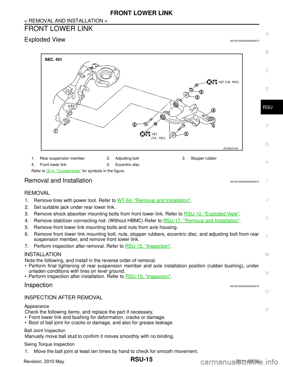
Exploded ViewINFOID:0000000006225673
Removal and InstallationINFOID:0000000006225674
REMOVAL
1. Remove tires with power tool. Refer to WT-64, "Removal and Installation".
2. Set suitable jack under rear lower link.
3. Remove shock absorber mounting bolts from front lower link. Refer to RSU-10, "
Exploded View".
4. Remove stabilizer connecting rod. (Without HBMC) Refer to RSU-17, "
Removal and Installation".
5. Remove front lower link mounting bolts and nuts from axle housing.
6. Remove front lower link mounting bolt, nuts, stopper rubbers, eccentric disc, and adjusting bolt from rear
suspension member, and remove front lower link.
7. Perform inspection after removal. Refer to RSU-15, "
Inspection".
INSTALLATION
Note the following, and install in the reverse order of removal.
Perform final tightening of rear suspension mem ber and axle installation position (rubber bushing), under
unladen conditions with tires on level ground.
Perform inspection after installation. Refer to RSU-15, "
Inspection".
InspectionINFOID:0000000006225675
INSPECTION AFTER REMOVAL
Appearance
Check the following items, and replace the part if necessary.
Front lower link and bushing for deformation, cracks or damage.
Boot of ball joint for cracks or damage, and also for grease leakage.
Ball Joint Inspection
Manually move ball stud to confirm it moves smoothly with no binding.
Swing Torque Inspection
1. Move the ball joint at least ten times by hand to check for smooth movement.
1. Rear suspension member 2. Adjusting bolt 3. Stopper rubber
4. Front lower link 5. Eccentric disc
Refer to GI-4, "
Components" for symbols in the figure.
JPEIB0231GB
Revision: 2010 May2011 QX56
Page 4271 of 5598

RSU-16
< REMOVAL AND INSTALLATION >
FRONT LOWER LINK
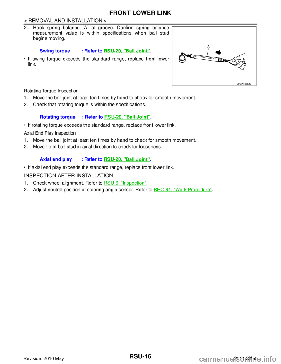
2. Hook spring balance (A) at groove. Confirm spring balancemeasurement value is within specifications when ball stud
begins moving.
If swing torque exceeds the standard range, replace front lower link.
Rotating Torque Inspection
1. Move the ball joint at least ten times by hand to check for smooth movement.
2. Check that rotating torque is within the specifications.
If rotating torque exceeds the standar d range, replace front lower link.
Axial End Play Inspection
1. Move the ball joint at least ten times by hand to check for smooth movement.
2. Move tip of ball stud in axial direction to check for looseness.
If axial end play exceeds the standard range, replace front lower link.
INSPECTION AFTER INSTALLATION
1. Check wheel alignment. Refer to RSU-6, "Inspection".
2. Adjust neutral position of steering angle sensor. Refer to BRC-64, "
Work Procedure".
Swing torque : Refer to
RSU-20, "
Ball Joint".
JPEIA0005ZZ
Rotating torque : Refer to RSU-20, "Ball Joint".
Axial end play : Refer to RSU-20, "
Ball Joint".
Revision: 2010 May2011 QX56
Page 4272 of 5598

REAR STABILIZERRSU-17
< REMOVAL AND INSTALLATION >
C
DF
G H
I
J
K L
M A
B
RSU
N
O P
REAR STABILIZER
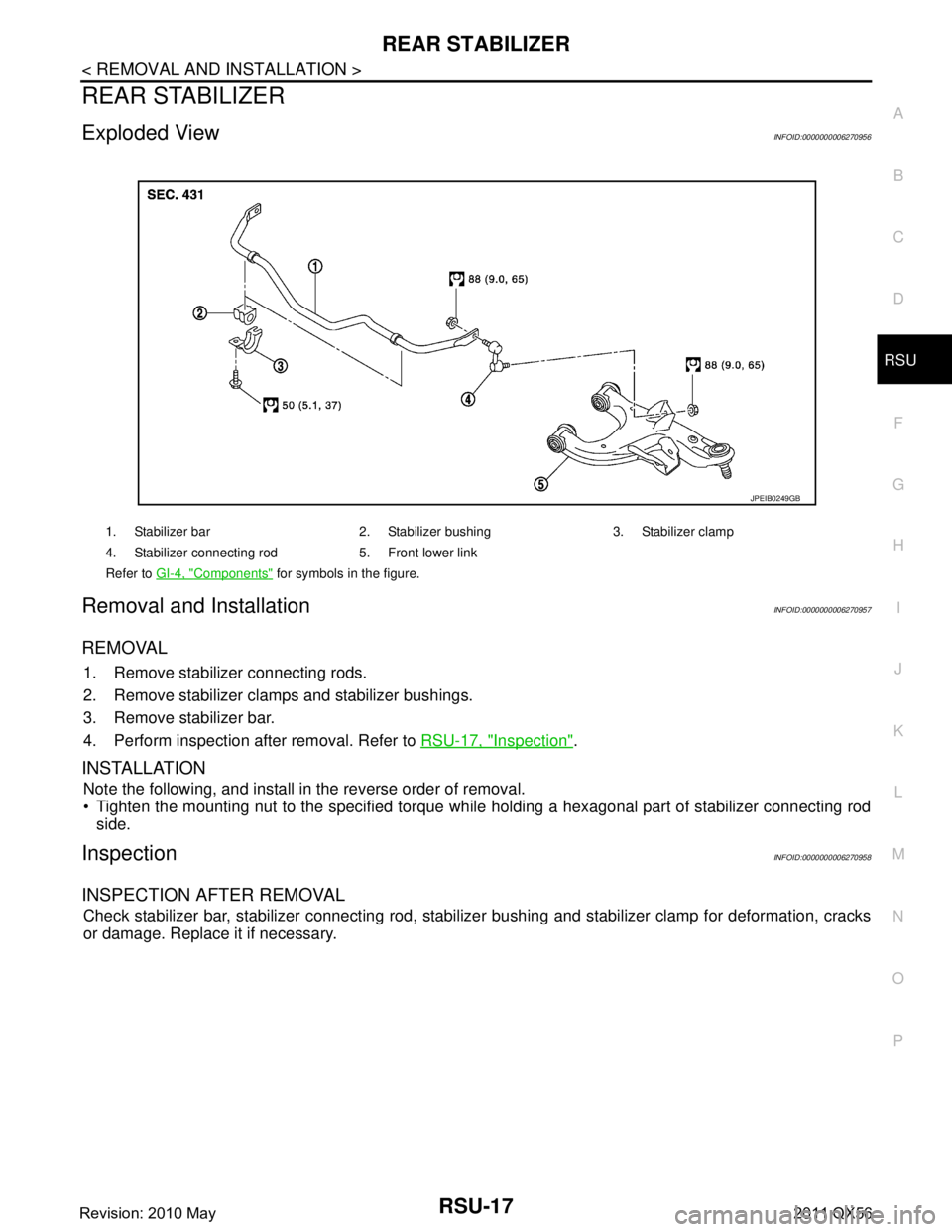
Exploded ViewINFOID:0000000006270956
Removal and InstallationINFOID:0000000006270957
REMOVAL
1. Remove stabilizer connecting rods.
2. Remove stabilizer clamps and stabilizer bushings.
3. Remove stabilizer bar.
4. Perform inspection after removal. Refer to RSU-17, "
Inspection".
INSTALLATION
Note the following, and install in the reverse order of removal.
Tighten the mounting nut to the specified torque wh ile holding a hexagonal part of stabilizer connecting rod
side.
InspectionINFOID:0000000006270958
INSPECTION AFTER REMOVAL
Check stabilizer bar, stabilizer connecting rod, stabiliz er bushing and stabilizer clamp for deformation, cracks
or damage. Replace it if necessary.
1. Stabilizer bar 2. Stabilizer bushing 3. Stabilizer clamp
4. Stabilizer connecting rod 5. Front lower link
Refer to GI-4, "
Components" for symbols in the figure.
JPEIB0249GB
Revision: 2010 May2011 QX56
Page 4275 of 5598

RSU-20
< SERVICE DATA AND SPECIFICATIONS (SDS)
SERVICE DATA AND SPECIFICATIONS (SDS)
SERVICE DATA AND SPECIFICATIONS (SDS)
SERVICE DATA AND SPECIFICATIONS (SDS)
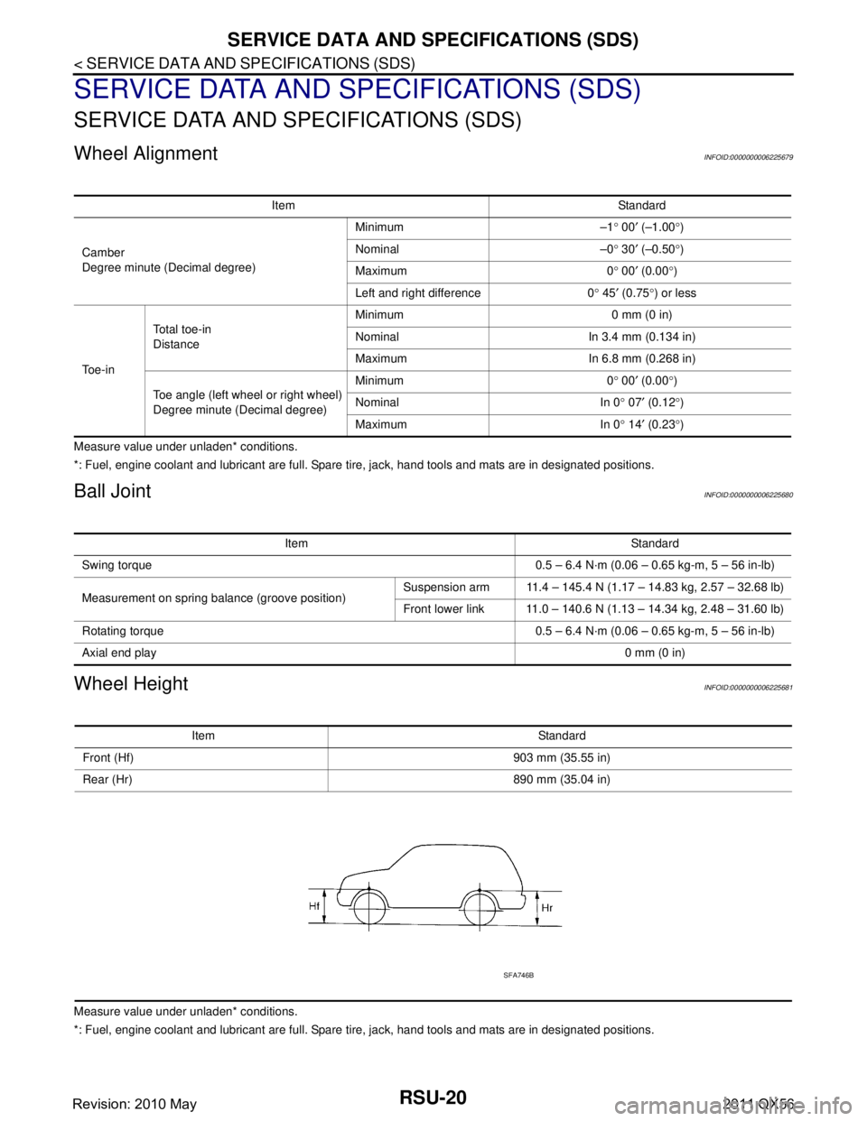
Wheel AlignmentINFOID:0000000006225679
Measure value under unladen* conditions.
*: Fuel, engine coolant and lubricant are full. Spare tire, jack, hand tools and mats are in designated positions.
Ball JointINFOID:0000000006225680
Wheel HeightINFOID:0000000006225681
Measure value under unladen* conditions.
*: Fuel, engine coolant and lubricant are full. Spare tire, jack, hand tools and mats are in designated positions.Item Standard
Camber
Degree minute (Decimal degree) Minimum –1
° 00 ′ (–1.00 °)
Nominal –0 ° 30 ′ (–0.50 °)
Maximum 0 ° 00 ′ (0.00 °)
Left and right difference 0 ° 45 ′ (0.75 °) or less
To e - i n Total toe-in
Distance
Minimum 0 mm (0 in)
Nominal In 3.4 mm (0.134 in)
Maximum In 6.8 mm (0.268 in)
Toe angle (left wheel or right wheel)
Degree minute (Decimal degree) Minimum 0
° 00 ′ (0.00 °)
Nominal In 0 ° 07 ′ (0.12 °)
Maximum In 0 ° 14 ′ (0.23 °)
Item Standard
Swing torque 0.5 – 6.4 N·m (0.06 – 0.65 kg-m, 5 – 56 in-lb)
Measurement on spring balance (groove position) Suspension arm 11.4 – 145.4 N (1.17 – 14.83 kg, 2.57 – 32.68 lb)
Front lower link 11.0 – 140.6 N (1.13 – 14.34 kg, 2.48 – 31.60 lb)
Rotating torque 0.5 – 6.4 N·m (0.06 – 0.65 kg-m, 5 – 56 in-lb)
Axial end play 0 mm (0 in)
Item Standard
Front (Hf) 903 mm (35.55 in)
Rear (Hr) 890 mm (35.04 in)
SFA746B
Revision: 2010 May2011 QX56
Page 4375 of 5598
![INFINITI QX56 2011 Factory Service Manual
CHECK SYSTEM PRESSURESCS-15
< BASIC INSPECTION > [HBMC]
C
D
F
G H
I
J
K L
M A
B
SCS
N
O P
BASIC INSPECTION
CHECK SYSTEM PRESSURE
Work ProcedureINFOID:0000000006256009
CAUTION:
Clean surrounding are INFINITI QX56 2011 Factory Service Manual
CHECK SYSTEM PRESSURESCS-15
< BASIC INSPECTION > [HBMC]
C
D
F
G H
I
J
K L
M A
B
SCS
N
O P
BASIC INSPECTION
CHECK SYSTEM PRESSURE
Work ProcedureINFOID:0000000006256009
CAUTION:
Clean surrounding are](/manual-img/42/57033/w960_57033-4374.png)
CHECK SYSTEM PRESSURESCS-15
< BASIC INSPECTION > [HBMC]
C
D
F
G H
I
J
K L
M A
B
SCS
N
O P
BASIC INSPECTION
CHECK SYSTEM PRESSURE
Work ProcedureINFOID:0000000006256009
CAUTION:
Clean surrounding areas of oil inj ection jack using steam before starting operation, since there may
be mud on it.
Clean oil pressure gauge (special service tool: KV40108000) jack with steam before use.
1. Lift up the vehicle.
2. Remove protector of PPMU.
3. Remove cap of oil injection jack.
4. Install an oil pressure gauge (SST: KV40108000) (A) to oil injec- tion jack.
CAUTION:
Jack must be securely inserted until a click sound can be
heard.
Pressure reducing valve (B) of the oil pressure gauge
must be closed.
5. Loosen needle valves A, C, and E of PPMU by approximately 2 rotations.
CAUTION:
Never loosen the needle valve more than required.
6. Refer to the figure and check the specified pressure.
7. Tighten needle valves A, C, and E of PPMU to the specified torque.
JSEIA0186ZZ
JSEIA0187ZZ
Tightening torque : 8.3 N·m (0.85 kg-m, 73 in-lb)
JSEIA0222GB
Revision: 2010 May2011 QX56
Page 4377 of 5598
![INFINITI QX56 2011 Factory Service Manual
PRESSURE REDUCING METHODSCS-17
< BASIC INSPECTION > [HBMC]
C
D
F
G H
I
J
K L
M A
B
SCS
N
O P
PRESSURE REDUCING METHOD
Work ProcedureINFOID:0000000006256010
CAUTION:
Clean surrounding areas of oil i INFINITI QX56 2011 Factory Service Manual
PRESSURE REDUCING METHODSCS-17
< BASIC INSPECTION > [HBMC]
C
D
F
G H
I
J
K L
M A
B
SCS
N
O P
PRESSURE REDUCING METHOD
Work ProcedureINFOID:0000000006256010
CAUTION:
Clean surrounding areas of oil i](/manual-img/42/57033/w960_57033-4376.png)
PRESSURE REDUCING METHODSCS-17
< BASIC INSPECTION > [HBMC]
C
D
F
G H
I
J
K L
M A
B
SCS
N
O P
PRESSURE REDUCING METHOD
Work ProcedureINFOID:0000000006256010
CAUTION:
Clean surrounding areas of oil inj ection jack using steam before starting operation, since there may
be mud on it.
Clean oil pressure gauge (special service tool: KV40108000) jack with steam before use.
1. Lift up the vehicle.
2. Remove protector of PPMU.
3. Remove cap of oil injection jack.
4. Install an oil pressure gauge (SST: KV40108000) (A) to oil injec- tion jack.
CAUTION:
Jack must be securely inserted until a click sound can beheard.
Pressure reducing valve (B) of the oil pressure gauge
must be closed.
5. Loosen needle valves A, C, and E of PPMU by approximately 2 rotations.
CAUTION:
Never loosen the needle valve more than required.
6. Loosen pressure reducing valve (A) of oil pressure gauge and then lower pressure.
CAUTION:
Be careful since oil drains sw iftly from oil drain hole (B).
7. Check that reading of oil pressure gauge is 0 MPa.
8. Tighten needle valves A, C, and E of PPMU to the specified torque.
JSEIA0186ZZ
JSEIA0187ZZ
Tightening torque : 8.3 N·m (0.85 kg-m, 73 in-lb)
JSEIA0188ZZ
Revision: 2010 May2011 QX56
Page 4379 of 5598
![INFINITI QX56 2011 Factory Service Manual
AIR BLEEDING METHODSCS-19
< BASIC INSPECTION > [HBMC]
C
D
F
G H
I
J
K L
M A
B
SCS
N
O P
8. Loosen needle valves A, C, and E of PPMU by approximately 2 rotations.
CAUTION:
Never loosen the needle val INFINITI QX56 2011 Factory Service Manual
AIR BLEEDING METHODSCS-19
< BASIC INSPECTION > [HBMC]
C
D
F
G H
I
J
K L
M A
B
SCS
N
O P
8. Loosen needle valves A, C, and E of PPMU by approximately 2 rotations.
CAUTION:
Never loosen the needle val](/manual-img/42/57033/w960_57033-4378.png)
AIR BLEEDING METHODSCS-19
< BASIC INSPECTION > [HBMC]
C
D
F
G H
I
J
K L
M A
B
SCS
N
O P
8. Loosen needle valves A, C, and E of PPMU by approximately 2 rotations.
CAUTION:
Never loosen the needle valve more than required.
9. Install bleeder tube and drain tank to bleeder valve in upper side of rear shock absorber RH.
10. Loosen bleeder valve and bleed air while sending oil by applying pressure using suspension oil pump, and then quickly tighten air
bleeder.
CAUTION:
Be careful that oil in suspensi on oil pump is not at half or
less.
11. Repeat step 10 until no air appears in bleeder tube.
12. Tighten bleeder valve to the specified torque. Refer to SCS-32, "
FRONT TUBE ASSEMBLY : Exploded
View" (front shock absorber), SCS-39, "PPMU, MIDDLE TUBE ASSEMB LY, PPMU PIPE : Exploded
View" (upper side of rear shock absorber).
13. Perform operation according to steps 9 to 12 in the order of rear shock absorber RH (lower side) → front
shock absorber RH (upper side and lower side) → rear shock absorber LH (upper side and lower side) →
front shock absorber LH (upper side and lower side).
14. Repeat steps 9 to 13 (2nd turn).
15. Refer to the figure and send oil by applying pressure.
16. Tighten needle valves A, C, and E of PPMU to the specified torque.
17. Set knob (A) of suspension oil pump to the direction as shown in the figure and check that reading of pressure gauge is 0 MPa.
18. Remove hose of suspension oil pump.
19. Install cap of oil injection jack.
20. Install protector of PPMU. Refer to SCS-39, "
PPMU, MIDDLE
TUBE ASSEMBLY, PPMU PIPE : Exploded View".
Lower side of rear shock absorber
Tightening torque : 8.3 N·m (0.85 kg-m, 73 in-lb)
JSEIA0187ZZ
JSEIA0236GB
Tightening torque : 8.3 N·m (0.85 kg-m, 73 in-lb)
JSEIA0193ZZ
Revision: 2010 May2011 QX56
Page 4380 of 5598
![INFINITI QX56 2011 Factory Service Manual
SCS-20
< BASIC INSPECTION >[HBMC]
CHECK INTERNAL LEAKAGE
CHECK INTERNAL LEAKAGE
Work ProcedureINFOID:0000000006256012
CAUTION:
Clean surrounding areas of
oil injection jack using steam before sta INFINITI QX56 2011 Factory Service Manual
SCS-20
< BASIC INSPECTION >[HBMC]
CHECK INTERNAL LEAKAGE
CHECK INTERNAL LEAKAGE
Work ProcedureINFOID:0000000006256012
CAUTION:
Clean surrounding areas of
oil injection jack using steam before sta](/manual-img/42/57033/w960_57033-4379.png)
SCS-20
< BASIC INSPECTION >[HBMC]
CHECK INTERNAL LEAKAGE
CHECK INTERNAL LEAKAGE
Work ProcedureINFOID:0000000006256012
CAUTION:
Clean surrounding areas of
oil injection jack using steam before starting operation, since there may
be mud on it.
Clean oil pressure gauge (special service tool: KV40108000) jack with steam before use.
1. Remove protector of PPMU.
2. Remove cap of oil injection jack.
3. Install an oil pressure gauge (SST: KV40108000) (A) to oil injec- tion jack.
CAUTION:
Jack must be securely inserted until a click sound can beheard.
Pressure reducing valve (B) of the oil pressure gauge
must be closed.
4. Loosen needle valves A, C, and E of PPMU by approximately 2 rotations. CAUTION:
Never loosen the needle valve more than required.
5. Lift up the vehicle. CAUTION:
Check that tires never contact the ground.
6. Tighten needle valves C and E of PPMU.
7. Loosen lock nut of needle valve D of PPMU and then tighten needle valve D.
8. Lift down the vehicle. CAUTION:
Check that the lift is fully lowered.
9. Write down a value of the oil pressure gauge after 5 minutes.
10. Tighten needle valve A of PPMU.
11. Loosen lock nut of needle valve B of PPMU and then tighten needle valve B.
12. Loosen needle valve C of PPMU by approximately 2 rotations. CAUTION:
Never loosen the needle valve more than required.
13. Read a value of oil pressure gauge.
14. Compare difference of reading with pressure reading in step 9.
15. Tighten needle valves A, C, and E of PPMU to the specified torque.
16. Loosen needle valves B and D of PPMU by approximatel y 2 rotations and then tighten lock nut to the
specified torque.
CAUTION:
Never loosen the needle valve more than required.
JSEIA0186ZZ
Pressure difference
0.1 MPa or more : Normal
0.1 MPa or less : Malfunction
: 8.3 N·m (0.85 kg-m, 73 in-lb)
JSEIA0187ZZ
Revision: 2010 May2011 QX56