2011 INFINITI QX56 torque
[x] Cancel search: torquePage 4463 of 5598

SE-4
< PRECAUTION >
PRECAUTIONS
PRECAUTION
PRECAUTIONS
Precaution for Supplemental Restraint System (SRS) "AIR BAG" and "SEAT BELT
PRE-TENSIONER"
INFOID:0000000006237842
The Supplemental Restraint System such as “A IR BAG” and “SEAT BELT PRE-TENSIONER”, used along
with a front seat belt, helps to reduce the risk or severi ty of injury to the driver and front passenger for certain
types of collision. This system includes seat belt switch inputs and dual stage front air bag modules. The SRS
system uses the seat belt switches to determine the front air bag deployment, and may only deploy one front
air bag, depending on the severity of a collision and w hether the front occupants are belted or unbelted.
Information necessary to service the system safely is included in the “SRS AIR BAG” and “SEAT BELT” of this
Service Manual.
WARNING:
• To avoid rendering the SRS inopera tive, which could increase the risk of personal injury or death in
the event of a collision that would result in air bag inflation, all maintenance must be performed by
an authorized NISS AN/INFINITI dealer.
Improper maintenance, including in correct removal and installation of the SRS, can lead to personal
injury caused by unintent ional activation of the system. For re moval of Spiral Cable and Air Bag
Module, see the “SRS AIR BAG”.
Do not use electrical test equipmen t on any circuit related to the SRS unless instructed to in this
Service Manual. SRS wiring harnesses can be identi fied by yellow and/or orange harnesses or har-
ness connectors.
PRECAUTIONS WHEN USING POWER TOOLS (AIR OR ELECTRIC) AND HAMMERS
WARNING:
When working near the Air Bag Diagnosis Sensor Unit or other Air Bag System sensors with the ignition ON or engine running, DO NOT use air or electric power tools or strike near the sensor(s)
with a hammer. Heavy vibration could activate the sensor(s) and deploy the air bag(s), possibly
causing serious injury.
When using air or electric power tools or hammers , always switch the ignition OFF, disconnect the
battery, and wait at least 3 minu tes before performing any service.
Service NoticeINFOID:0000000006217352
When removing or installing various parts, place a cloth or padding onto the vehicle body to prevent
scratches.
Handle trim, molding, instruments, grille, etc. carefull y during removing or installing. Be careful not to oil or
damage them.
Apply sealing compound where necessary when installing parts.
When applying sealing compound, be careful that t he sealing compound never protrudes from parts.
When replacing any metal parts (for example body outer panel, members, etc.), always take rust prevention
measures.
Precaution for WorkINFOID:0000000006217353
When removing or disassembling each component, be careful not to damage or deform it. If a component
may be subject to interference, al ways protect it with a shop cloth.
When removing (disengaging) components with a screwdriver or similar tool, always wrap the component
with a shop cloth or vinyl tape to protect it.
Protect the removed parts with a shop cloth and keep them.
Replace a deformed or damaged clip.
If a part is specified as a non-reusable part, always replace it with new one.
Always tighten bolts and nuts securely to the specified torque.
After reinstallation is complete, always check that each part works normally.
Follow the steps below to clean components.
- Water soluble foul: Dip a soft cloth into lukewarm water, and wring the water out of the cloth to wipe the fouled area.
Then rub with a soft and dry cloth.
Revision: 2010 May2011 QX56
Page 4989 of 5598

ST-2
STEERING WHEEL ...........................................33
Exploded View ..................................................... ...33
Removal and Installation ........................................33
STEERING COLUMN ........................................34
Exploded View ..................................................... ...34
Removal and Installation ........................................34
Inspection ...............................................................35
STEERING SHAFT ............................................37
Exploded View ..................................................... ...37
Removal and Installation ........................................37
Inspection ...............................................................39
STEERING GEAR AND LINKAGE ....................41
Exploded View ..................................................... ...41
Removal and Installation ........................................42
Disassembly and Assembly ....................................43
Inspection ...............................................................46
POWER STEERING OIL PUMP ........................48
Exploded View ..................................................... ...48
Removal and Installation ........................................49
Disassembly and Assembly ....................................50
Inspection ...............................................................52
HYDRAULIC LINE .......................................... ...54
Exploded View ..................................................... ...54
HEATED STEERING WHEEL SWITCH ............56
Exploded View ..................................................... ...56
Removal and Installation .........................................56
SERVICE DATA AND SPECIFICATIONS
(SDS) .......... ................................................
57
SERVICE DATA AND SPECIFICATIONS
(SDS) .............................................................. ...
57
General Specifications ......................................... ...57
Steering Wheel Axial End Play and Play ................57
Steering Wheel Turning Force ................................57
Steering Angle ........................................................57
Steering Column Length .........................................57
Steering Column Mounting Dimensions ..................57
Steering Column Operating Range .........................57
Steering Shaft Sliding Range ..................................58
Rack Sliding Force ..................................................58
Rack Stroke ............................................................58
Socket Swing Force and Rotating Torque ..............58
Socket Axial End Play .............................................58
Inner Socket Length ................................................58
Relief Oil Pressure ..................................................58
Revision: 2010 May2011 QX56
Page 4992 of 5598
PREPARATIONST-5
< PREPARATION >
C
DE
F
H I
J
K L
M A
B
ST
N
O P
PREPARATION
PREPARATION
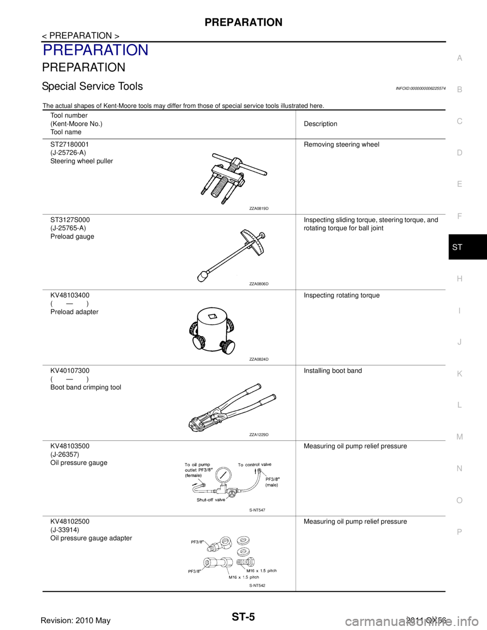
Special Service ToolsINFOID:0000000006225574
The actual shapes of Kent-Moore t ools may differ from those of special service tools illustrated here.
Tool number
(Kent-Moore No.)
Tool name Description
ST27180001
(J-25726-A)
Steering wheel puller Removing steering wheel
ST3127S000
(J-25765-A)
Preload gauge Inspecting sliding torque, steering torque, and
rotating torque for ball joint
KV48103400
(—)
Preload adapter Inspecting rotating torque
KV40107300
(—)
Boot band crimping tool Installing boot band
KV48103500
(J-26357)
Oil pressure gauge Measuring oil pump relief pressure
KV48102500
(J-33914)
Oil pressure gauge adapter Measuring oil pump relief pressure
ZZA0819D
ZZA0806D
ZZA0824D
ZZA1229D
S-NT547
S-NT542
Revision: 2010 May2011 QX56
Page 5016 of 5598
NOISE, VIBRATION AND HARSHNESS (NVH) TROUBLESHOOTINGST-29
< SYMPTOM DIAGNOSIS >
C
DE
F
H I
J
K L
M A
B
ST
N
O P
NOISE, VIBRATION AND HARSHN ESS (NVH) TROUBLESHOOTING
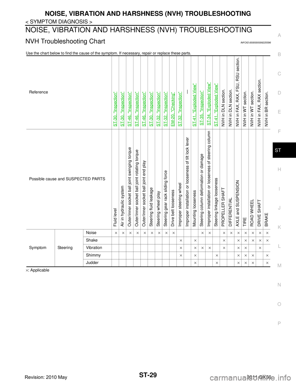
NVH Troubleshooting ChartINFOID:0000000006225596
Use the chart below to find the cause of the symp tom. If necessary, repair or replace these parts.
×: ApplicableReference
ST-30, "
Inspection
"
ST-30, "
Inspection
"
ST-46, "
Inspection
"
ST-46, "
Inspection
"
ST-46, "
Inspection
"
ST-30, "
Inspection
"
ST-32, "
Inspection
"
ST-32, "
Inspection
"
EM-20, "
Checking
"
ST-32, "
Inspection
"—
ST-41, "
Exploded View
"
ST-35, "
Inspection
"
ST-34, "
Exploded View
"
ST-41, "
Exploded View
"
NVH in DLN section.
NVH in DLN section.
NVH in FAX, RAX, FSU, RSU section.
NVH in WT section.
NVH in WT section.
NVH in FAX, RAX section.
NVH in BR section.
Possible cause and SUSPECTED PARTS
Fluid level
Air in hydraulic system
Outer/inner socket ball joint swinging torque
Outer/inner socket ball joint rotating torque
Outer/inner socket ball joint end play
Steering fluid leakage
Steering wheel play
Steering gear rack sliding force
Drive belt looseness
Improper steering wheel
Improper installation or looseness of tilt lock lever
Mounting looseness
Steering column deformation or damage
Improper installation or looseness of steering column
Steering linkage looseness
PROPELLER SHAFT
DIFFERENTIAL
AXLE and SUSPENSION
TIRE
ROAD WHEEL
DRIVE SHAFT
BRAKE
Symptom Steering Noise
××××××××× ×× ×××××××
Shake × × × ×××××
Vibration ××××××××
Shimmy ×× × ××××
Judder ××××××
Revision: 2010 May2011 QX56
Page 5022 of 5598
STEERING COLUMNST-35
< REMOVAL AND INSTALLATION >
C
DE
F
H I
J
K L
M A
B
ST
N
O P
If necessary, remove telescopic motor, tilt motor, and brackets.
12. Perform inspection after removal. Refer to ST-35, "
Inspection".
INSTALLATION
Note the following, and install in the reverse order of removal.
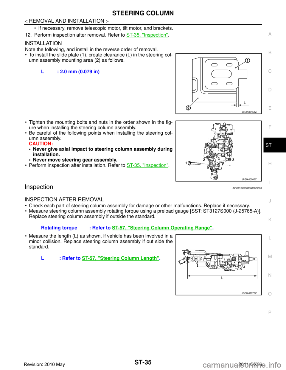
To install the slide plate (1), create clearance (L) in the steering col-
umn assembly mounting area (2) as follows.
Tighten the mounting bolts and nuts in the order shown in the fig- ure when installing the steering column assembly.
Be careful of the following points when installing the steering col- umn assembly.
CAUTION:
Never give axial impact to steering column assembly during installation.
Never move steering gear assembly.
Perform inspection after installation. Refer to ST-35, "
Inspection".
InspectionINFOID:0000000006225603
INSPECTION AFTER REMOVAL
Check each part of steering column assembly for damage or other malfunctions. Replace if necessary.
Measure steering column assembly rotating torque using a preload gauge [SST: ST3127S000 (J-25765-A)]. Replace steering column assembly if outside the standard.
Measure the length (L) as shown, if vehicle has been involved in a minor collision. Replace steering column assembly if out side the
standard. L : 2.0 mm (0.079 in)
JSGIA0315ZZ
JPGIA0026ZZ
Rotating torque : Refer to
ST-57, "Steering Column Operating Range".
L : Refer to ST-57, "
Steering Column Length".
JSGIA0797ZZ
Revision: 2010 May2011 QX56
Page 5025 of 5598
ST-38
< REMOVAL AND INSTALLATION >
STEERING SHAFT
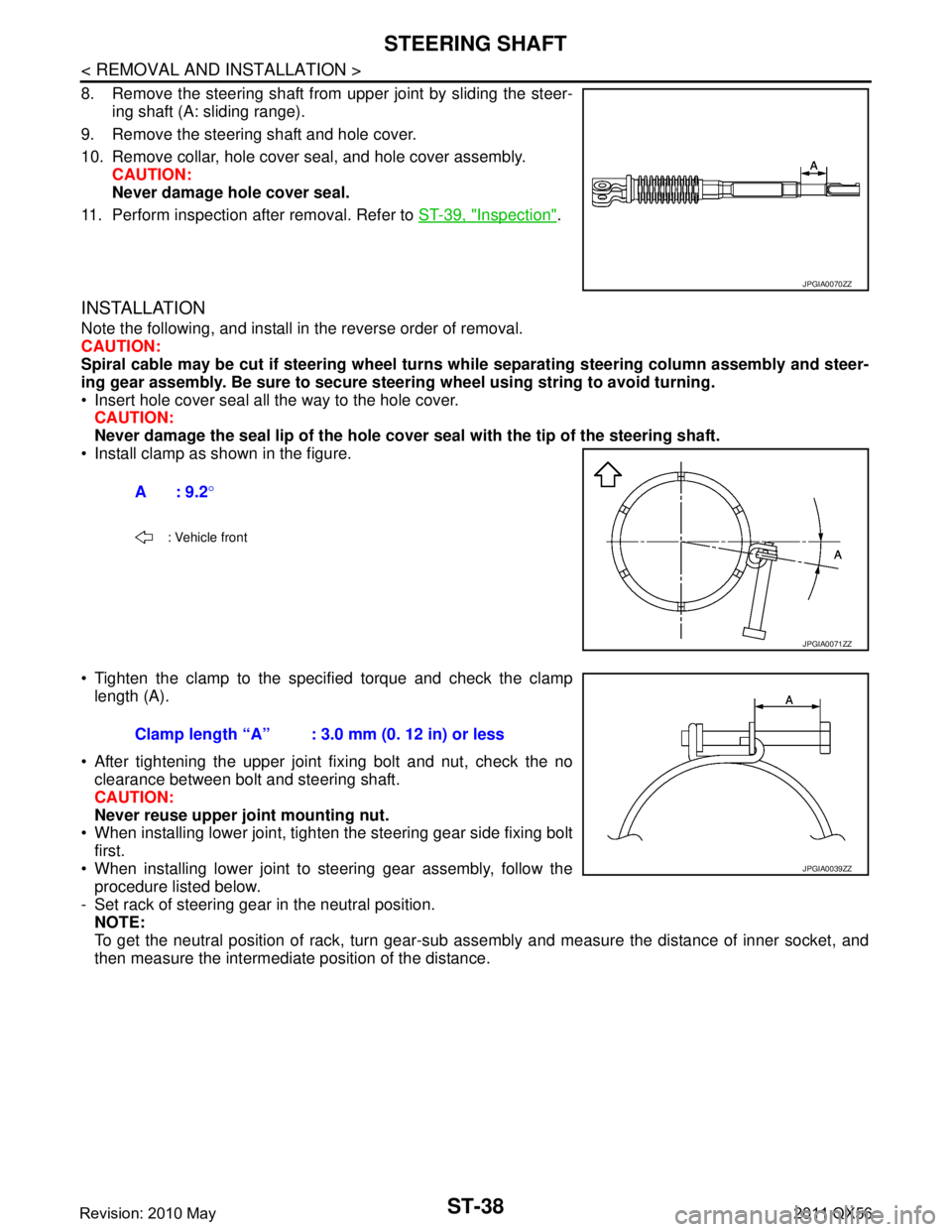
8. Remove the steering shaft from upper joint by sliding the steer-ing shaft (A: sliding range).
9. Remove the steering shaft and hole cover.
10. Remove collar, hole cover seal, and hole cover assembly. CAUTION:
Never damage hole cover seal.
11. Perform inspection after removal. Refer to ST-39, "
Inspection".
INSTALLATION
Note the following, and install in the reverse order of removal.
CAUTION:
Spiral cable may be cut if steering wheel turns while separating steering column assembly and steer-
ing gear assembly. Be sure to secure steer ing wheel using string to avoid turning.
Insert hole cover seal all the way to the hole cover. CAUTION:
Never damage the seal lip of the hole cover seal with the tip of the steering shaft.
Install clamp as shown in the figure.
Tighten the clamp to the spec ified torque and check the clamp
length (A).
After tightening the upper joint fixing bolt and nut, check the no clearance between bolt and steering shaft.
CAUTION:
Never reuse upper joint mounting nut.
When installing lower joint, tighten the steering gear side fixing bolt
first.
When installing lower joint to steering gear assembly, follow the procedure listed below.
- Set rack of steering gear in the neutral position. NOTE:
To get the neutral position of rack, turn gear-sub as sembly and measure the distance of inner socket, and
then measure the intermediate position of the distance.
JPGIA0070ZZ
A: 9.2 °
: Vehicle front
JPGIA0071ZZ
Clamp length “A” : 3.0 mm (0. 12 in) or less
JPGIA0039ZZ
Revision: 2010 May2011 QX56
Page 5031 of 5598
ST-44
< REMOVAL AND INSTALLATION >
STEERING GEAR AND LINKAGE
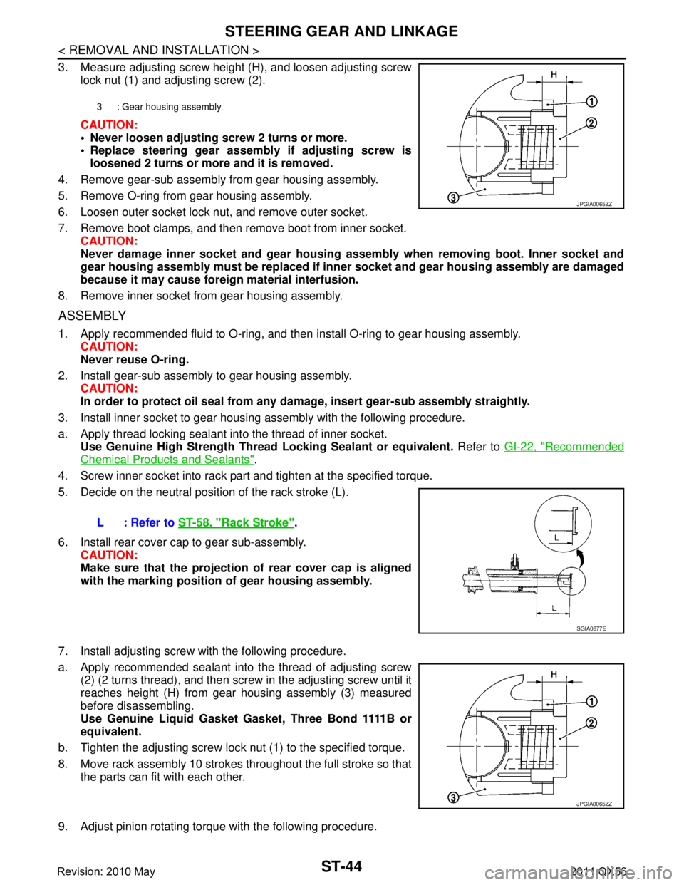
3. Measure adjusting screw height (H), and loosen adjusting screwlock nut (1) and adjusting screw (2).
CAUTION:
Never loosen adjusting screw 2 turns or more.
Replace steering gear assembly if adjusting screw is
loosened 2 turns or more and it is removed.
4. Remove gear-sub assembly from gear housing assembly.
5. Remove O-ring from gear housing assembly.
6. Loosen outer socket lock nut, and remove outer socket.
7. Remove boot clamps, and then remove boot from inner socket. CAUTION:
Never damage inner socket and gear housing assembly when removing boot. Inner socket and
gear housing assembly must be replaced if inne r socket and gear housing assembly are damaged
because it may cause foreign material interfusion.
8. Remove inner socket from gear housing assembly.
ASSEMBLY
1. Apply recommended fluid to O-ring, and then install O-ring to gear housing assembly. CAUTION:
Never reuse O-ring.
2. Install gear-sub assembly to gear housing assembly. CAUTION:
In order to protect oil seal from any da mage, insert gear-sub assembly straightly.
3. Install inner socket to gear housing assembly with the following procedure.
a. Apply thread locking sealant into the thread of inner socket. Use Genuine High Strength Thread Locking Sealant or equivalent. Refer to GI-22, "
Recommended
Chemical Products and Sealants".
4. Screw inner socket into rack part and tighten at the specified torque.
5. Decide on the neutral position of the rack stroke (L).
6. Install rear cover cap to gear sub-assembly. CAUTION:
Make sure that the projection of rear cover cap is aligned
with the marking position of gear housing assembly.
7. Install adjusting screw with the following procedure.
a. Apply recommended sealant into the thread of adjusting screw (2) (2 turns thread), and then screw in the adjusting screw until it
reaches height (H) from gear housing assembly (3) measured
before disassembling.
Use Genuine Liquid Gasket Gasket, Three Bond 1111B or
equivalent.
b. Tighten the adjusting screw lock nut (1) to the specified torque.
8. Move rack assembly 10 strokes throughout the full stroke so that the parts can fit with each other.
9. Adjust pinion rotating torque with the following procedure.
3 : Gear housing assembly
JPGIA0065ZZ
L : Refer to ST-58, "Rack Stroke".
SGIA0877E
JPGIA0065ZZ
Revision: 2010 May2011 QX56
Page 5032 of 5598
STEERING GEAR AND LINKAGEST-45
< REMOVAL AND INSTALLATION >
C
DE
F
H I
J
K L
M A
B
ST
N
O P
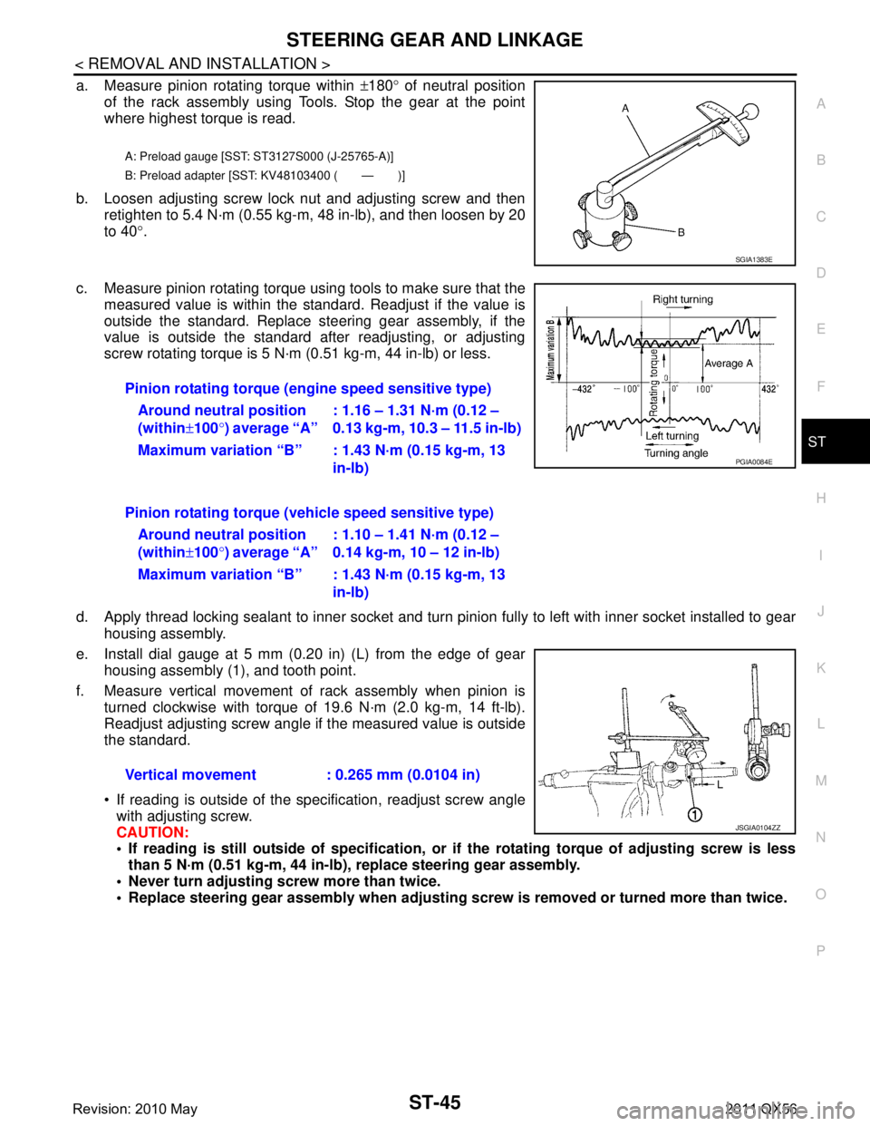
a. Measure pinion rotating torque within ±180 ° of neutral position
of the rack assembly using Tools. Stop the gear at the point
where highest torque is read.
b. Loosen adjusting screw lock nut and adjusting screw and then retighten to 5.4 N·m (0.55 kg-m, 48 in-lb), and then loosen by 20
to 40 °.
c. Measure pinion rotating torque using tools to make sure that the measured value is within the standard. Readjust if the value is
outside the standard. Replace steering gear assembly, if the
value is outside the standard after readjusting, or adjusting
screw rotating torque is 5 N·m (0.51 kg-m, 44 in-lb) or less.
d. Apply thread locking sealant to inner socket and turn pinion fully to left with inner socket installed to gear housing assembly.
e. Install dial gauge at 5 mm (0.20 in) (L) from the edge of gear housing assembly (1), and tooth point.
f. Measure vertical movement of rack assembly when pinion is turned clockwise with torque of 19.6 N·m (2.0 kg-m, 14 ft-lb).
Readjust adjusting screw angle if the measured value is outside
the standard.
If reading is outside of the specification, readjust screw angle
with adjusting screw.
CAUTION:
If reading is still outside of sp ecification, or if the rotating torque of adjusting screw is less
than 5 N·m (0.51 kg-m, 44 in-lb), replace steering gear assembly.
Never turn adjusting scr ew more than twice.
Replace steering gear assembly when adjusting screw is removed or turned more than twice.
A: Preload gauge [SST: ST3127S000 (J-25765-A)]
B: Preload adapter [SST: KV48103400 ( — )]
SGIA1383E
Pinion rotating torque (engine speed sensitive type)
Around neutral position
(within ±100 °) average “A” : 1.16 – 1.31 N·m (0.12 –
0.13 kg-m, 10.3 – 11.5 in-lb)
Maximum variation “B” : 1.43 N·m (0.15 kg-m, 13 in-lb)
Pinion rotating torque (veh icle speed sensitive type)
Around neutral position
(within ±100 °) average “A” : 1.10 – 1.41 N·m (0.12 –
0.14 kg-m, 10 – 12 in-lb)
Maximum variation “B” : 1.43 N·m (0.15 kg-m, 13 in-lb)
Vertical movement : 0.265 mm (0.0104 in)
PGIA0084E
JSGIA0104ZZ
Revision: 2010 May2011 QX56