2011 INFINITI QX56 torque
[x] Cancel search: torquePage 3434 of 5598
![INFINITI QX56 2011 Factory Service Manual
LAN-14
< SYSTEM DESCRIPTION >[CAN FUNDAMENTAL]
TROUBLE DIAGNOSIS
Example: CAN-H, CAN-L Harness Short Circuit
CAN Diagnosis with CONSULT-IIIINFOID:0000000006220519
CAN diagnosis on CONSULT-III extract INFINITI QX56 2011 Factory Service Manual
LAN-14
< SYSTEM DESCRIPTION >[CAN FUNDAMENTAL]
TROUBLE DIAGNOSIS
Example: CAN-H, CAN-L Harness Short Circuit
CAN Diagnosis with CONSULT-IIIINFOID:0000000006220519
CAN diagnosis on CONSULT-III extract](/manual-img/42/57033/w960_57033-3433.png)
LAN-14
< SYSTEM DESCRIPTION >[CAN FUNDAMENTAL]
TROUBLE DIAGNOSIS
Example: CAN-H, CAN-L Harness Short Circuit
CAN Diagnosis with CONSULT-IIIINFOID:0000000006220519
CAN diagnosis on CONSULT-III extracts the root
cause by receiving the following information.
Response to the system call
Control unit diagnosis information
Self-diagnosis
CAN diagnostic support monitor
SKIB8741E
Unit name Major symptom
ECM Engine torque limiting is affected, and shift harshness increases.
Engine speed drops.
BCM Reverse warning chime does not sound.
The front wiper moves under continuous operation mode even though the front
wiper switch being in the intermittent position.
The room lamp does not turn ON.
The engine does not start (if an error or malfunction occurs while turning the igni- tion switch OFF.)
The steering lock does not release (if an error or malfunction occurs while turning the ignition switch OFF.)
EPS control unit The steeri ng effort increases.
Combination meter The tachometer and the speedometer do not move.
Warning lamps turn ON.
Indicator lamps do not turn ON.
ABS actuator and electric unit (control unit) Normal operation.
TCM No impact on operation.
IPDM E/R When the ignition switch is ON,
The headlamps (Lo) turn ON.
The cooling fan continues to rotate.
Revision: 2010 May2011 QX56
Page 3448 of 5598
![INFINITI QX56 2011 Factory Service Manual
LAN-28
< SYSTEM DESCRIPTION >[CAN]
SYSTEM
Check CAN system type from the vehicle shape and equipment.
CAN COMMUNICATION SYSTEM : CA
N Communication Signal ChartINFOID:0000000006220533
Refer to LAN-17 INFINITI QX56 2011 Factory Service Manual
LAN-28
< SYSTEM DESCRIPTION >[CAN]
SYSTEM
Check CAN system type from the vehicle shape and equipment.
CAN COMMUNICATION SYSTEM : CA
N Communication Signal ChartINFOID:0000000006220533
Refer to LAN-17](/manual-img/42/57033/w960_57033-3447.png)
LAN-28
< SYSTEM DESCRIPTION >[CAN]
SYSTEM
Check CAN system type from the vehicle shape and equipment.
CAN COMMUNICATION SYSTEM : CA
N Communication Signal ChartINFOID:0000000006220533
Refer to LAN-17, "How to Use CAN Communication Signal Chart" for how to use CAN communication signal
chart.
T: Transmit R: Receive
1. ICC sensor
A. With ICC system
JSMIA0342ZZ
Signal nameECM
4WD
ABS
TCM
A-BAG
AFSAV
BCM
CGW
HVAC
M&A
STRG
TPMS
IPDM-E ADP
PSB
E-SUS ICC
PWBD
A/C compressor request
signal TR
Accelerator pedal position
signal TRRR
R
ASCD OD cancel request
signal TR
ASCD operation signal T R
ASCD status signal T R
Closed throttle position sig-
nal TR
R
Cooling fan speed request
signal TR
Engine and A/T integrated
control signal TR
RT
Engine coolant temperature
signal TRR
Engine restart request sig-
nal TRR
TR
Engine speed signal T R R R R R R R
Engine status signal T R R R
Engine torque signal T R
Fuel consumption monitor
signal TRR
ICC brake switch signal T R
ICC prohibition signal T R
ICC steering switch signal T R
Malfunctioning indicator
lamp signal TR
N idle instruction signal TR
RT
Revision: 2010 May2011 QX56
Page 3661 of 5598
![INFINITI QX56 2011 Factory Service Manual
LU-8
< PERIODIC MAINTENANCE >
ENGINE OIL
5. Install the oil pressure gauge [SST: ST25051001 (J25695-1)] (A)and hose [SST: ST25052000 (J25695-2)] (B).
6. Start the engine and warm it up to normal oper INFINITI QX56 2011 Factory Service Manual
LU-8
< PERIODIC MAINTENANCE >
ENGINE OIL
5. Install the oil pressure gauge [SST: ST25051001 (J25695-1)] (A)and hose [SST: ST25052000 (J25695-2)] (B).
6. Start the engine and warm it up to normal oper](/manual-img/42/57033/w960_57033-3660.png)
LU-8
< PERIODIC MAINTENANCE >
ENGINE OIL
5. Install the oil pressure gauge [SST: ST25051001 (J25695-1)] (A)and hose [SST: ST25052000 (J25695-2)] (B).
6. Start the engine and warm it up to normal operating temperature.
7. Check the engine oil pressure with engine running under no-load. Refer to LU-17, "
EngineOilPressure".
CAUTION:
If the difference is extreme, check the oil passages and oil pump for leaks and blockages.
8. After the inspections, install oil pressure switch as follows:
a. Remove old liquid gasket adhering to oil pressure switch and engine.
b. Apply liquid gasket and tighten oil pressure switch to the specification. Use Genuine RTV Silicone Seal ant or equivalent. Refer to GI-22, "
Recommended Chemical Prod-
ucts and Sealants".
c. After warming up engine, make sure there is no leakage of engine oil with engine running.
DrainingINFOID:0000000006289617
WARNING:
Be careful not to burn yourself, as th e engine and engine oil may be hot.
Prolonged and repeated contact with used engine oil may cause skin cancer; try to avoid direct skin
contact with used oil. If skin contact is made, wash thoroughly with soap or hand cleaner as soon as
possible.
1. Warm up the engine, and check for any oil leaks.
2. Stop the engine and wait for at least 10 minutes.
3. Remove drain plug and oil filler cap to drain the old oil.
RefillingINFOID:0000000006289618
1. Install drain plug with new washer. CAUTION:
Be sure to clean drain plug and install with new washer.
2. Refill with new engine oil. Engine oil specification and viscosity:
Refer to MA-10, "
Fluids and Lubricants".
CAUTION:
The refill capacity depends on the engine oi l temperature and drain time. Use these specifica-
tions for reference only.
Always use oil level gauge to determine the proper amount of engine oil in engine.
3. Warm up the engine and check area around drain plug and oil filter for engine oil leakage.
4. Stop the engine and wait for 10 minutes.
5. Check the engine oil level. Refer to LU-7, "
Inspection".
JPBIA0074ZZ
Oil pressure switch torque : Refer to EM-57, "Exploded View".
Tightening torque : Refer to EM-54, "
Exploded View".
Engine oil capacity : Refer to LU-17, "
Periodical Maintenance Specification".
Revision: 2010 May2011 QX56
Page 3687 of 5598
ENGINE MAINTENANCEMA-17
< PERIODIC MAINTENANCE >
C
DE
F
G H
I
J
K L
M B
MA
N
O A
FUEL LINES : InspectionINFOID:0000000006394850
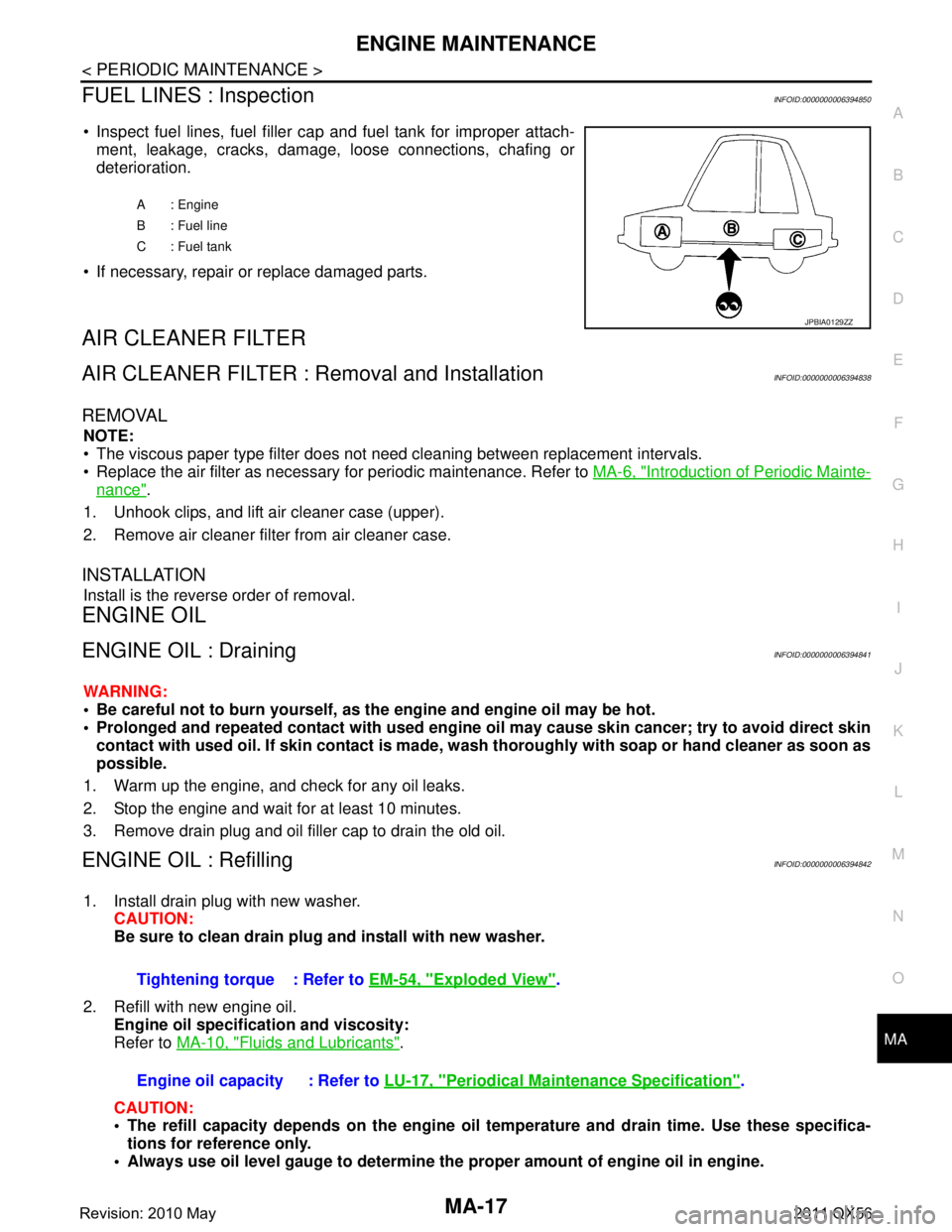
Inspect fuel lines, fuel filler cap and fuel tank for improper attach-
ment, leakage, cracks, damage, loose connections, chafing or
deterioration.
If necessary, repair or replace damaged parts.
AIR CLEANER FILTER
AIR CLEANER FILTER : Removal and InstallationINFOID:0000000006394838
REMOVAL
NOTE:
The viscous paper type filter does not need cleaning between replacement intervals.
Replace the air filter as necessary for periodic maintenance. Refer to MA-6, "
Introduction of Periodic Mainte-
nance".
1. Unhook clips, and lift air cleaner case (upper).
2. Remove air cleaner filter from air cleaner case.
INSTALLATION
Install is the reverse order of removal.
ENGINE OIL
ENGINE OIL : DrainingINFOID:0000000006394841
WARNING:
Be careful not to burn yourself, as th e engine and engine oil may be hot.
Prolonged and repeated contact with used engine oil may cau se skin cancer; try to avoid direct skin
contact with used oil. If skin contact is made, w ash thoroughly with soap or hand cleaner as soon as
possible.
1. Warm up the engine, and check for any oil leaks.
2. Stop the engine and wait for at least 10 minutes.
3. Remove drain plug and oil filler cap to drain the old oil.
ENGINE OIL : RefillingINFOID:0000000006394842
1. Install drain plug with new washer. CAUTION:
Be sure to clean drain plug and install with new washer.
2. Refill with new engine oil. Engine oil specificat ion and viscosity:
Refer to MA-10, "
Fluids and Lubricants".
CAUTION:
The refill capacity depends on the engine oi l temperature and drain time. Use these specifica-
tions for reference only.
Always use oil level gauge to determine the proper amount of engine oil in engine.
A : Engine
B : Fuel line
C : Fuel tank
JPBIA0129ZZ
Tightening torque : Refer to EM-54, "Exploded View".
Engine oil capacity : Refer to LU-17, "
Periodical Maintenance Specification".
Revision: 2010 May2011 QX56
Page 3691 of 5598
CHASSIS MAINTENANCEMA-21
< PERIODIC MAINTENANCE >
C
DE
F
G H
I
J
K L
M B
MA
N
O A
CHASSIS MAINTENANCE
EXHAUST SYSTEM
EXHAUST SYSTEM : InspectionINFOID:0000000006220926
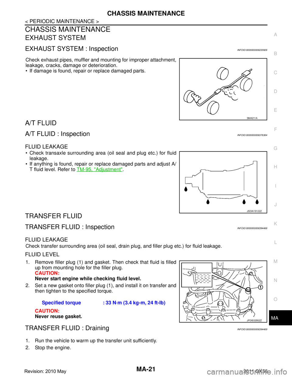
Check exhaust pipes, muffler and mounting for improper attachment,
leakage, cracks, damage or deterioration.
If damage is found, repair or replace damaged parts.
A/T FLUID
A/T FLUID : InspectionINFOID:0000000006376364
FLUID LEAKAGE
Check transaxle surrounding area (oil seal and plug etc.) for fluid
leakage.
If anything is found, repair or replace damaged parts and adjust A/ T fluid level. Refer to TM-95, "
Adjustment".
TRANSFER FLUID
TRANSFER FLUID : InspectionINFOID:0000000006394468
FLUID LEAKAGE
Check transfer surrounding area (oil seal, drain plug, and filler plug etc.) for fluid leakage.
FLUID LEVEL
1. Remove filler plug (1) and gasket. Then check that fluid is filled
up from mounting hole for the filler plug.
CAUTION:
Never start engine whil e checking fluid level.
2. Set a new gasket onto filler plug (1), and install it on transfer and then tighten to the specified torque.
CAUTION:
Never reuse gasket.
TRANSFER FLUID : DrainingINFOID:0000000006394469
1. Run the vehicle to warm up the transfer unit sufficiently.
2. Stop the engine.
SMA211A
JSDIA1912ZZ
Specified torque : 33 N·m (3.4 kg-m, 24 ft-lb)
JPDIE0295ZZ
Revision: 2010 May2011 QX56
Page 3692 of 5598
MA-22
< PERIODIC MAINTENANCE >
CHASSIS MAINTENANCE
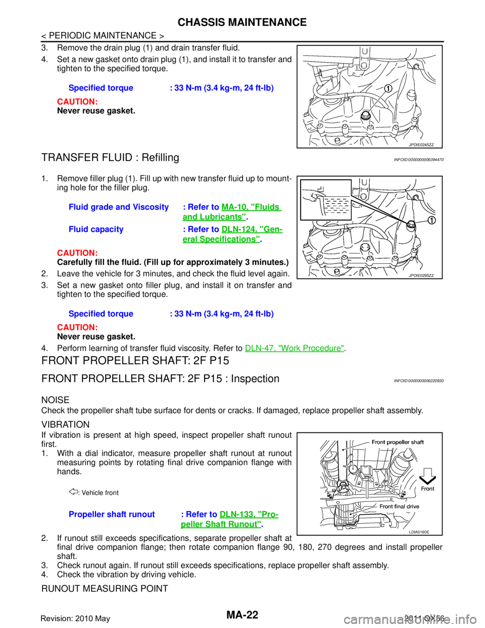
3. Remove the drain plug (1) and drain transfer fluid.
4. Set a new gasket onto drain plug (1), and install it to transfer andtighten to the specified torque.
CAUTION:
Never reuse gasket.
TRANSFER FLUID : RefillingINFOID:0000000006394470
1. Remove filler plug (1). Fill up with new transfer fluid up to mount-
ing hole for the filler plug.
CAUTION:
Carefully fill the fluid. (Fill up for approximately 3 minutes.)
2. Leave the vehicle for 3 minutes, and check the fluid level again.
3. Set a new gasket onto filler plug, and install it on transfer and tighten to the specified torque.
CAUTION:
Never reuse gasket.
4. Perform learning of transfer fluid viscosity. Refer to DLN-47, "
Work Procedure".
FRONT PROPELLER SHAFT: 2F P15
FRONT PROPELLER SHAFT: 2F P15 : InspectionINFOID:0000000006220930
NOISE
Check the propeller shaft tube surface for dents or cr acks. If damaged, replace propeller shaft assembly.
VIBRATION
If vibration is present at high speed, inspect propeller shaft runout
first.
1. With a dial indicator, measure propeller shaft runout at runout
measuring points by rotating final drive companion flange with
hands.
2. If runout still exceeds specifications, separate propeller shaft at final drive companion flange; then rotate companion flange 90, 180, 270 degrees and install propeller
shaft.
3. Check runout again. If runout still exceeds s pecifications, replace propeller shaft assembly.
4. Check the vibration by driving vehicle.
RUNOUT MEASURING POINT
Specified torque : 33 N-m (3.4 kg-m, 24 ft-lb)
JPDIE0245ZZ
Fluid grade and Viscosity : Refer to MA-10, "Fluids
and Lubricants".
Fluid capacity : Refer to DLN-124, "
Gen-
eral Specifications".
Specified torque : 33 N-m (3.4 kg-m, 24 ft-lb)
JPDIE0295ZZ
: Vehicle front
Propeller shaft runout : Refer to DLN-133, "Pro-
peller Shaft Runout".LDIA0160E
Revision: 2010 May2011 QX56
Page 3695 of 5598
CHASSIS MAINTENANCEMA-25
< PERIODIC MAINTENANCE >
C
DE
F
G H
I
J
K L
M B
MA
N
O A
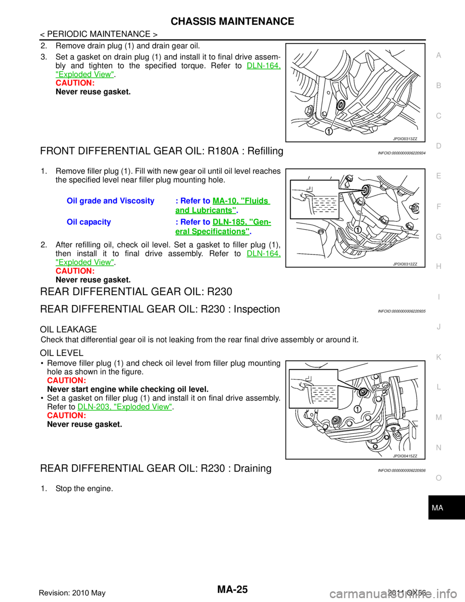
2. Remove drain plug (1) and drain gear oil.
3. Set a gasket on drain plug (1) and install it to final drive assem-
bly and tighten to the specified torque. Refer to DLN-164,
"Exploded View".
CAUTION:
Never reuse gasket.
FRONT DIFFERENTIAL GEAR OIL: R180A : RefillingINFOID:0000000006220934
1. Remove filler plug (1). Fill with new gear oil until oil level reaches
the specified level near filler plug mounting hole.
2. After refilling oil, check oil level. Set a gasket to filler plug (1), then install it to final drive assembly. Refer to DLN-164,
"Exploded View".
CAUTION:
Never reuse gasket.
REAR DIFFERENTIAL GEAR OIL: R230
REAR DIFFERENTIAL GEAR OIL: R230 : InspectionINFOID:0000000006220935
OIL LEAKAGE
Check that differential gear oil is not leaking fr om the rear final drive assembly or around it.
OIL LEVEL
Remove filler plug (1) and check oil level from filler plug mounting
hole as shown in the figure.
CAUTION:
Never start engine while checking oil level.
Set a gasket on filler plug (1) and install it on final drive assembly. Refer to DLN-203, "
Exploded View".
CAUTION:
Never reuse gasket.
REAR DIFFERENTIAL GEAR OIL: R230 : DrainingINFOID:0000000006220936
1. Stop the engine.
JPDID0313ZZ
Oil grade and Viscosity : Refer to MA-10, "Fluids
and Lubricants".
Oil capacity : Refer to DLN-185, "
Gen-
eral Specifications".
JPDID0312ZZ
JPDID0415ZZ
Revision: 2010 May2011 QX56
Page 3696 of 5598
MA-26
< PERIODIC MAINTENANCE >
CHASSIS MAINTENANCE
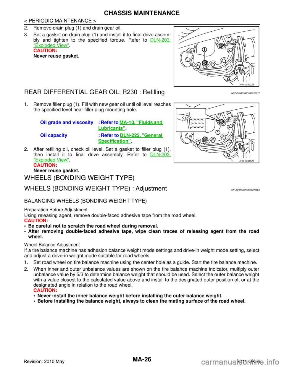
2. Remove drain plug (1) and drain gear oil.
3. Set a gasket on drain plug (1) and install it to final drive assem-bly and tighten to the specified torque. Refer to DLN-203,
"Exploded View".
CAUTION:
Never reuse gasket.
REAR DIFFERENTIAL GEAR OIL: R230 : RefillingINFOID:0000000006220937
1. Remove filler plug (1). Fill with new gear oil until oil level reaches
the specified level near filler plug mounting hole.
2. After refilling oil, check oil level. Set a gasket to filler plug (1), then install it to final drive assembly. Refer to DLN-203,
"Exploded View".
CAUTION:
Never reuse gasket.
WHEELS (BONDING WEIGHT TYPE)
WHEELS (BONDING WEIG HT TYPE) : AdjustmentINFOID:0000000006394852
BALANCING WHEELS (BONDING WEIGHT TYPE)
Preparation Before Adjustment
Using releasing agent, remove double-faced adhesive tape from the road wheel.
CAUTION:
Be careful not to scratch th e road wheel during removal.
After removing double-faced adhesive tape, wi pe clean traces of releasing agent from the road
wheel.
Wheel Balance Adjustment
If a tire balance machine has adhesion balance weight m ode settings and drive-in weight mode setting, select
and adjust a drive-in weight mode suitable for road wheels.
1. Set road wheel on tire balance machine using the center hole as a guide. Start the tire balance machine.
2. When inner and outer unbalance values are shown on the tire balance machine indicator, multiply outer unbalance value by 5/3 to determine balance weight t hat should be used. Select the outer balance weight
with a value closest to the calculated value above and in stall to the designated outer position of, or at the
designated angle in relation to the road wheel.
CAUTION:
Never install the inner balance weight be fore installing the outer balance weight.
Before installing the balance weight, always to clean the mating surface of the road wheel.
JPDID0392ZZ
Oil grade and viscosity : Refer to MA-10, "Fluids and
Lubricants".
Oil capacity : Refer to DLN-222, "
General
Specification".
JPDID0415ZZ
Revision: 2010 May2011 QX56