2011 INFINITI QX56 transmission
[x] Cancel search: transmissionPage 2662 of 5598
EM-100
< UNIT REMOVAL AND INSTALLATION >
ENGINE ASSEMBLY
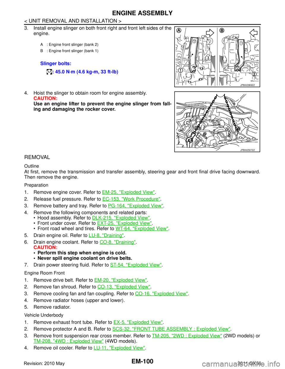
3. Install engine slinger on both front right and front left sides of theengine.
4. Hoist the slinger to obtain room for engine assembly. CAUTION:
Use an engine lifter to prevent the engine slinger from fall-
ing and damaging the rocker cover.
REMOVAL
Outline
At first, remove the transmission and transfer assemb ly, steering gear and front final drive facing downward.
Then remove the engine.
Preparation
1. Remove engine cover. Refer to EM-25, "Exploded View".
2. Release fuel pressure. Refer to EC-153, "
Work Procedure".
3. Remove battery and tray. Refer to PG-164, "
Exploded View".
4. Remove the following components and related parts: Hood assembly. Refer to DLK-215, "
Exploded View".
Front under cover. Refer to EXT-25, "
Exploded View".
Front road wheel and tires. Refer to WT-64, "
Exploded View".
5. Drain engine oil. Refer to LU-8, "
Draining".
6. Drain engine coolant. Refer to CO-8, "
Draining".
CAUTION:
Perform this step when engine is cold.
Never spill engine coolant on drive belts.
7. Drain power steering fluid. Refer to ST-54, "
Exploded View".
Engine Room Front
1. Remove drive belt. Refer to EM-20, "Exploded View".
2. Remove fan shroud. Refer to CO-13, "
Exploded View".
3. Remove cooling fan and fan coupling. Refer to CO-16, "
Exploded View".
4. Remove radiator hoses (upper and lower).
5. Remove radiator.
Vehicle Underbody
1. Remove exhaust front tube. Refer to EX-5, "Exploded View".
2. Remove protector A and B. Refer to SCS-32, "
FRONT TUBE ASSEMBLY : Exploded View".
3. Remove front suspension rear cross member. Refer to TM-205, "
2WD : Exploded View" (2WD models) or
TM-208, "
4WD : Exploded View" (4WD models).
4. Remove oil cooler. Refer to LU-11, "
Exploded View".
A : Engine front slinger (bank 2)
B : Engine front slinger (bank 1)
Slinger bolts:
: 45.0 N·m (4.6 kg-m, 33 ft-lb)
JPBIA3969ZZ
JPBIA2507ZZ
Revision: 2010 May2011 QX56
Page 2664 of 5598
EM-102
< UNIT REMOVAL AND INSTALLATION >
ENGINE ASSEMBLY
INSTALLATION
Install in the reverse order of removal.
CAUTION:
When replacing an engine or transmission you must make sure the dowels are installed correctly
during re-assembly.Improper alignment caused by mi ssing dowels may cause vibration, oil leaks or
breakage of drivetrain components.
InspectionINFOID:0000000006289578
INSPECTION AFTER INSTALLATION
Inspection for Leakage
The following are procedures for checking fluid leakage, lubricant leakage. Before starting engine, check oil/fluid levels includi ng engine coolant and engine oil. If any are less than the
required quantity, fill them to the specified level. Refer to MA-10, "
Fluids and Lubricants".
Follow the procedure below to check for fuel leakage.
- Turn ignition switch to the “ON” position (with engi ne stopped). With fuel pressure applied to fuel piping,
check for fuel leakage at connection points.
- Start engine. With engine speed increased, che ck again for fuel leakage at connection points.
Run engine to check for unusual noise and vibration. NOTE:
If hydraulic pressure inside chain tensioner drops af ter removal/installation, slack in guide may generate a
pounding noise during and just after the engine start. However, this does not indicate a malfunction. The
noise will stop after hydraulic pressure rises.
Warm up engine thoroughly to check that there is no leak age of fuel, or any oil/fluids including engine oil and
engine coolant.
Bleed air from lines and hoses of applic able lines, such as in cooling system.
After cooling down engine, again check oil/fluid levels including engine oil and engine coolant. Refill them to
the specified level, if necessary.
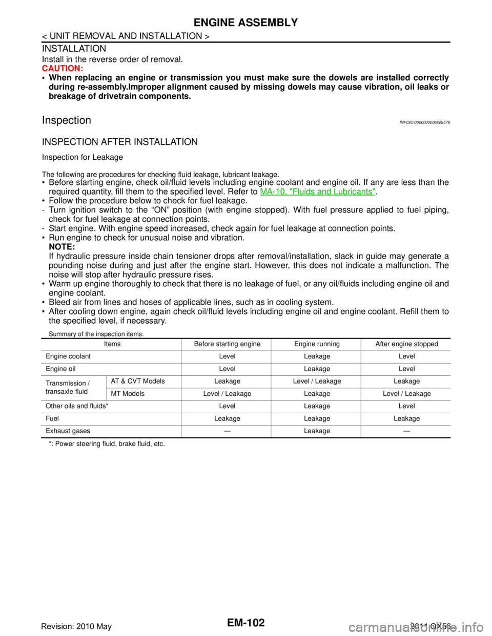
Summary of the inspection items:
*: Power steering fluid, brake fluid, etc. Items Before starting engine Engine running After engine stopped
Engine coolant Level Leakage Level
Engine oil Level Leakage Level
Transmission /
transaxle fluid AT & CVT Models Leakage Level / Leakage Leakage
MT Models Level / Leakage Leakage Level / Leakage
Other oils and fluids* Level Leakage Level
Fuel Leakage Leakage Leakage
Exhaust gases — Leakage —
Revision: 2010 May2011 QX56
Page 2665 of 5598

ENGINE STAND SETTINGEM-103
< UNIT DISASSEMBLY AND ASSEMBLY >
C
DE
F
G H
I
J
K L
M A
EM
NP
O
UNIT DISASSEMBLY AND ASSEMBLY
ENGINE STAND SETTING
SettingINFOID:0000000006289579
NOTE:
Explained here is how to disassemble with engine stand s
upporting transmission surface. When using a differ-
ent type of engine stand, note the difference in the steps, etc.
1. Remove the engine assembly from the vehicle. Refer to EM-98, "
Exploded View".
2. Remove crankshaft pulley. Refer to EM-96, "
FRONT OIL SEAL : Removal and Installation".
NOTE:
The drive plate is fixed with a ring gear stopper [SST: KV10119200 (J-49277)]. Loosen the crankshaft pul-
ley mounting bolts before installing the engine stand.
3. Remove the parts that may restrict installation of engine to a widely used engine stand. Fix crankshaft with a ring gear stopper [SST: KV10119200 (J-49277)]. Loosen drive plate mounting bolt
with power tool.
Check for deformation or damage of drive plate. Refer to EM-115, "
Inspection".
NOTE:
The procedure is described assuming that you us e a widely used engine stand holding the surface, to
which transmission is installed.
4. Remove pilot converter using the pilot bushing puller (commercial service tool), if necessary.
5. Lift the engine with hoist to inst all it onto the widely used engine stand.
CAUTION:
Use an engine stand that has a load capacity [240 kg (529 lb) or more] large enough for supporting
the engine weight.
If the load capacity of the stand is not adequate, remove the following parts beforehand to reduce the potential risk of overturning the stand.
- Remove intake manifold. Refer to EM-30, "
Exploded View".
- Remove fuel injector and fuel tube assembly. Refer to EM-48, "
Exploded View".
- Remove ignition coil. Refer to EM-29, "
Exploded View".
- Remove rocker cover. Refer to EM-33, "
Exploded View".
- Remove exhaust manifold. Refer to EM-40, "
Exploded View".
- Other removable brackets. NOTE:
The figure shows an example of widely used engine stand (A)
that can hold mating surface of transmission with drive plate
removed.
CAUTION:
Before removing the hang ing chains, check the engine
stand is stable and there is no risk of overturning.
6. Drain engine oil. Refer to LU-8, "
Draining".
JPBIA0190ZZ
Revision: 2010 May2011 QX56
Page 2669 of 5598
CYLINDER BLOCKEM-107
< UNIT DISASSEMBLY AND ASSEMBLY >
C
DE
F
G H
I
J
K L
M A
EM
NP
O
Disassembly and AssemblyINFOID:0000000006289583
DISASSEMBLY
1. Remove the following parts:
Oil pans (lower and upper): Refer to EM-54, "
Exploded View" and EM-57, "Exploded View".
Front cover and timing chain: Refer to EM-61, "
Exploded View".
Cylinder head: Refer to EM-86, "
Exploded View".
2. Remove knock sensor. CAUTION:
Carefully handle knock sensor avoiding shocks.
3. Remove oil filter (for VVEL ladder assembly ) from cylinder block, if necessary. Refer to EM-86, "
Exploded
View".
4. Remove piston and connecting rod assembly as per the following: Before removing piston and connecting rod assembly, check the connecting rod side clearance. Refer to
EM-115, "
Inspection".
CAUTION:
Be careful not to drop connecting r od bearing, and to scratch the surface.
a. Position crankshaft pin corresponding to connecting rod to be removed onto the bottom dead center.
b. Loosen mounting bolts, and remove connecting rod bearing cap.
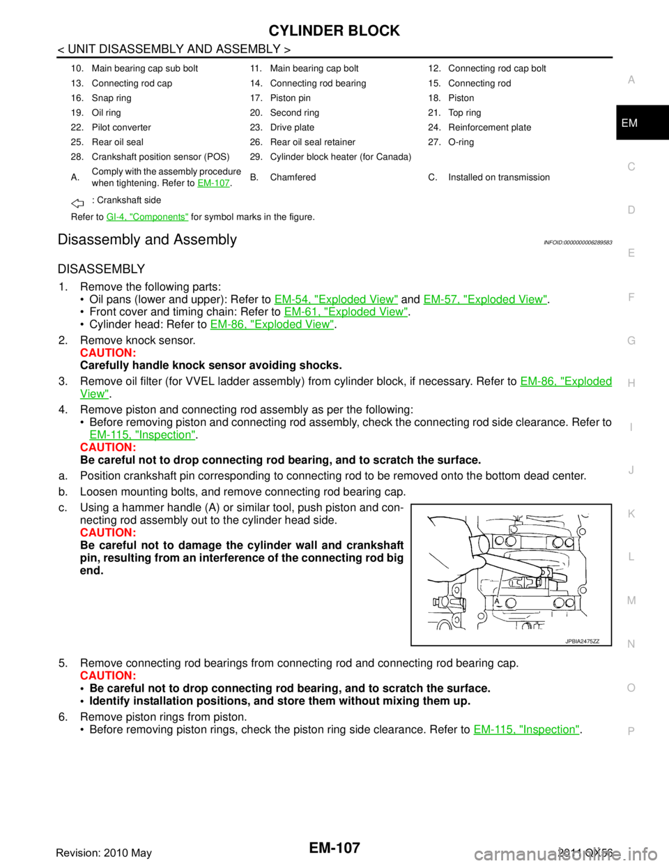
c. Using a hammer handle (A) or similar tool, push piston and con- necting rod assembly out to the cylinder head side.
CAUTION:
Be careful not to damage the cylinder wall and crankshaft
pin, resulting from an interf erence of the connecting rod big
end.
5. Remove connecting rod bearings from connecting rod and connecting rod bearing cap.
CAUTION:
Be careful not to drop connecting rod bearing, and to scratch the surface.
Identify installation positions, and store them without mixing them up.
6. Remove piston rings from piston. Before removing piston rings, check the piston ring side clearance. Refer to EM-115, "
Inspection".
10. Main bearing cap sub bolt 11. Main bearing cap bolt 12. Connecting rod cap bolt
13. Connecting rod cap 14. Connecting rod bearing 15. Connecting rod
16. Snap ring 17. Piston pin 18. Piston
19. Oil ring 20. Second ring 21. Top ring
22. Pilot converter 23. Drive plate 24. Reinforcement plate
25. Rear oil seal 26. Rear oil seal retainer 27. O-ring
28. Crankshaft position sensor (POS) 29. Cylinder block heater (for Canada)
A.Comply with the assembly procedure
when tightening. Refer to
EM-107
.B. Chamfered C. Installed on transmission
: Crankshaft side
Refer to GI-4, "
Components" for symbol marks in the figure.
JPBIA2475ZZ
Revision: 2010 May2011 QX56
Page 2735 of 5598
![INFINITI QX56 2011 Factory Service Manual
DIAGNOSIS SYSTEM (BCM)EXL-25
< SYSTEM DESCRIPTION > [XENON TYPE]
C
D
E
F
G H
I
J
K
M A
B
EXL
N
O P
ACTIVE TEST
*: Only models for Canada display this item.
FLASHER
FLASHER : CONSULT-III F unction (BC INFINITI QX56 2011 Factory Service Manual
DIAGNOSIS SYSTEM (BCM)EXL-25
< SYSTEM DESCRIPTION > [XENON TYPE]
C
D
E
F
G H
I
J
K
M A
B
EXL
N
O P
ACTIVE TEST
*: Only models for Canada display this item.
FLASHER
FLASHER : CONSULT-III F unction (BC](/manual-img/42/57033/w960_57033-2734.png)
DIAGNOSIS SYSTEM (BCM)EXL-25
< SYSTEM DESCRIPTION > [XENON TYPE]
C
D
E
F
G H
I
J
K
M A
B
EXL
N
O P
ACTIVE TEST
*: Only models for Canada display this item.
FLASHER
FLASHER : CONSULT-III F unction (BCM - FLASHER)INFOID:0000000006213912
WORK SUPPORT
DOOR SW-DR
[On/Off] The switch status input from front door switch (driver side)
DOOR SW-AS
[On/Off] The switch status input from front door switch (passenger side)
DOOR SW-RR
[On/Off] The switch status input from rear door switch RH
DOOR SW- RL
[On/Off] The switch status input from rear door switch LH
DOOR SW-BK
[On/Off] The switch status input from back door switch
OPTICAL SENSOR
[On/Off] The sensor status input from optical sensor
OPTI SEN (DTCT)
[V] The value of outside brightness voltage input from the optical sensor
OPTI SEN (FILT)
[V] The value of outside brightness voltage filtered by BCM
Monitor item
[Unit] Description
Test item Operation Description
TAIL LAMP On
Transmits the position light request signal to IPDM E/R via CAN commu-
nication to turn the tail lamp ON
Off Stops the tail lamp request signal transmission
HEAD LAMP Hi
Transmits the high beam request signal via CAN communication to turn
the headlamp (HI)
Lo Transmits the low beam request signal via CAN communication to turn
the headlamp (LO)
Off Stops the high & low beam request signal transmission
FR FOG LAMP On
Transmits the front fog lights request signal to IPDM E/R via CAN com-
munication to turn the front fog lamp ON
Off Stops the front light request signal transmission
RR FOG LAMP On
NOTE:
This item is indicated, but can not tested
Off
DAYTIME RUNNING LIGHT* On
Transmits the front fog lights request signal to IPDM E/R via CAN com-
munication to turn the front fog lamp ON (daytime running light system)
Off Stops the front light request signal transmission (daytime running light
system)
ILL DIM SIGNAL On Transmits the dimmer signal to combination meter via CAN communi-
cation and dims combination meter
Transmits the dimmer signal to AV control unit and dims display
Off Stops the dimmer signal transmission
Revision: 2010 May2011 QX56
Page 2901 of 5598
FAX-1
TRANSMISSION & DRIVELINE
CEF
G H
I
J
K L
M
SECTION FA X
A
B
FA X
N
O P
CONTENTS
FRONT AXLE
2WD
PRECAUTION ................ ...............................
3
PRECAUTIONS .............................................. .....3
Precaution for Supplemental Restraint System
(SRS) "AIR BAG" and "SEAT BELT PRE-TEN-
SIONER" ............................................................. ......
3
Precaution Necessary for Steering Wheel Rota-
tion after Battery Disconnect .....................................
3
PREPARATION ............................................5
PREPARATION .............................................. .....5
Commercial Service Tools .................................. ......5
SYMPTOM DIAGNOSIS ...............................6
NOISE, VIBRATION AND HARSHNESS
(NVH) TROUBLESHOOTING ........................ .....
6
NVH Troubleshooting Chart ................................ ......6
PERIODIC MAINTENANCE ..........................7
FRONT WHEEL HUB AND KNUCKLE ......... .....7
Inspection ............................................................ ......7
REMOVAL AND INSTALLATION ................8
FRONT WHEEL HUB AND KNUCKLE ......... .....8
Exploded View .................................................... ......8
Removal and Installation ...........................................8
Inspection ..................................................................9
SERVICE DATA AND SPECIFICATIONS
(SDS) ......... ................................. ..................
10
SERVICE DATA AND SPECIFICATIONS
(SDS) .............................................................. ....
10
Wheel Hub and Bearing Assembly ..................... ....10
4WDPRECAUTION ...............
...............................
11
PRECAUTIONS .................................................11
Precaution for Supplemental Restraint System
(SRS) "AIR BAG" and "SEAT BELT PRE-TEN-
SIONER" ............................................................. ....
11
Precaution Necessary for Steering Wheel Rota-
tion after Battery Disconnect ...................................
11
Precautions for Drive Shaft ......................................12
PREPARATION ...........................................13
PREPARATION .................................................13
Special Service Tools .......................................... ....13
Commercial Service Tools .......................................13
SYMPTOM DIAGNOSIS ..............................15
NOISE, VIBRATION AND HARSHNESS
(NVH) TROUBLESHOOTING ...........................
15
NVH Troubleshooting Chart ................................ ....15
PERIODIC MAINTENANCE ........................16
FRONT WHEEL HUB AND KNUCKLE ............16
Inspection ............................................................ ....16
FRONT DRIVE SHAFT .....................................17
Inspection ................................................................17
REMOVAL AND INSTALLATION ...............18
FRONT WHEEL HUB AND KNUCKLE ............18
Exploded View ..................................................... ....18
Removal and Installation .........................................18
Inspection ................................................................20
FRONT DRIVE SHAFT BOOT ..........................21
Exploded View .........................................................21
Removal and Installation .........................................21
Inspection ................................................................21
FRONT DRIVE SHAFT .....................................22
Revision: 2010 May2011 QX56
Page 2967 of 5598
HOW TO USE THIS MANUALGI-3
< HOW TO USE THIS MANUAL >
C
DE
F
G H
I
J
K L
M B
GI
N
O PHOW TO USE THIS MANUAL
HOW TO USE THIS MANUAL
DescriptionINFOID:0000000006280835
This volume explains “Removal, Disassembly, Inst allation, Inspection and Adjustment” and “Trouble Diag-
noses”.
Te r m sINFOID:0000000006280836
The captions WARNING and CAUTION warn you of steps that must be followed to prevent personal injury
and/or damage to some part of the vehicle.
WARNING indicates the possibility of personal injury if instructions are not followed.
CAUTION indicates the possibility of component damage if instructions are not followed.
BOLD TYPED STATEMENTS except WARNING and CAUTION give you helpful information.
Standard value: Tolerance at inspection and adjustment.
Limit value: The maximum or minimum limit val ue that should not be exceeded at inspection and adjust-
ment.
UnitsINFOID:0000000006280837
The UNITS given in this manual are primarily expressed as the SI UNIT (International System of Unit), and
alternatively expressed in the metr ic system and in the yard/pound system.
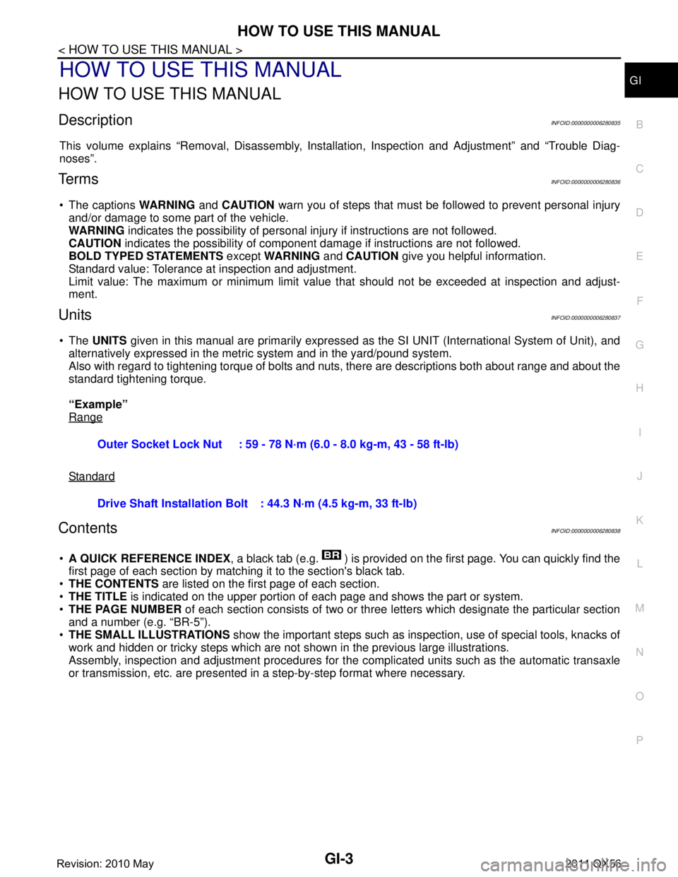
Also with regard to tightening torque of bolts and nuts, there are descriptions both about range and about the
standard tightening torque.
“Example”
Range
Standard
ContentsINFOID:0000000006280838
A QUICK REFERENCE INDEX , a black tab (e.g. ) is provided on the first page. You can quickly find the
first page of each section by matching it to the section's black tab.
THE CONTENTS are listed on the first page of each section.
THE TITLE is indicated on the upper portion of each page and shows the part or system.
THE PAGE NUMBER of each section consists of two or three letters which designate the particular section
and a number (e.g. “BR-5”).
THE SMALL ILLUSTRATIONS show the important steps such as ins pection, use of special tools, knacks of
work and hidden or tricky steps which are not s hown in the previous large illustrations.
Assembly, inspection and adjustment procedures for the complicated units such as the automatic transaxle
or transmission, etc. are presented in a step-by-step format where necessary.
Outer Socket Lock Nut : 59 - 78 N·m (6.0 - 8.0 kg-m, 43 - 58 ft-lb)
Drive Shaft Installation Bolt
: 44.3 N·m (4.5 kg-m, 33 ft-lb)
Revision: 2010 May2011 QX56
Page 2975 of 5598
HOW TO READ WIRING DIAGRAMSGI-11
< HOW TO USE THIS MANUAL >
C
DE
F
G H
I
J
K L
M B
GI
N
O P
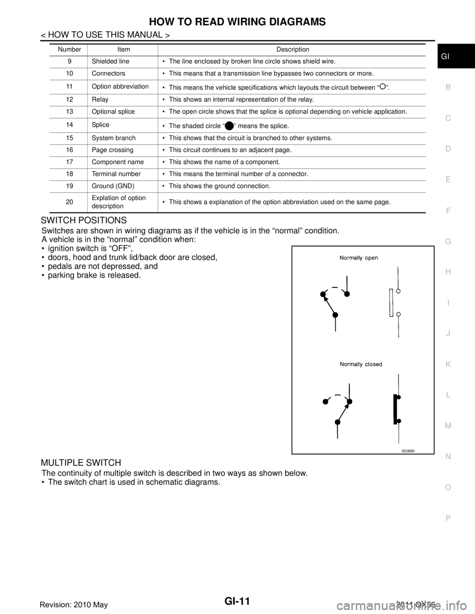
SWITCH POSITIONS
Switches are shown in wiring diagrams as if the vehicle is in the “normal” condition.
A vehicle is in the “normal” condition when:
ignition switch is “OFF”,
doors, hood and trunk lid/back door are closed,
pedals are not depressed, and
parking brake is released.
MULTIPLE SWITCH
The continuity of multiple switch is described in two ways as shown below.
The switch chart is used in schematic diagrams.
9 Shielded line The line enclosed by broken line circle shows shield wire.
10 Connectors This means that a transmission line bypasses two connectors or more.
11 Option abbreviation This means the vehicle specifications which layouts the circuit between “ ”.
12 Relay This shows an internal representation of the relay.
13 Optional splice The open circle shows that the splice is optional depending on vehicle application.
14 Splice The shaded circle “ ” means the splice.
15 System branch This shows that the circuit is branched to other systems.
16 Page crossing This circuit continues to an adjacent page.
17 Component name This shows the name of a component.
18 Terminal number This means the terminal number of a connector.
19 Ground (GND) This shows the ground connection.
20 Explation of option
description This shows a explanation of the option abbreviation used on the same page.
Number Item Description
SGI860
Revision: 2010 May2011 QX56