2011 INFINITI QX56 transmission
[x] Cancel search: transmissionPage 5356 of 5598
![INFINITI QX56 2011 Factory Service Manual
TM-268
< UNIT DISASSEMBLY AND ASSEMBLY >[7AT: RE7R01B]
TRANSMISSION ASSEMBLY
Check torque converter one-way clutch using a check tool as shown
at figure.
1. Insert a check tool into the groove of bea INFINITI QX56 2011 Factory Service Manual
TM-268
< UNIT DISASSEMBLY AND ASSEMBLY >[7AT: RE7R01B]
TRANSMISSION ASSEMBLY
Check torque converter one-way clutch using a check tool as shown
at figure.
1. Insert a check tool into the groove of bea](/manual-img/42/57033/w960_57033-5355.png)
TM-268
< UNIT DISASSEMBLY AND ASSEMBLY >[7AT: RE7R01B]
TRANSMISSION ASSEMBLY
Check torque converter one-way clutch using a check tool as shown
at figure.
1. Insert a check tool into the groove of bearing support built into
one-way clutch outer race.
2. When fixing bearing support with a check tool, rotate one-way clutch spline using a screwdriver.
3. Make sure that inner race rotates clockwise only. If not, replace
torque converter assembly.
1st One-way Clutch
Check operation of 1st one-way clutch.
1. Install 1st one-way clutch (1) to front brake hub (with under drivecarrier).
2. Hold 1st one-way clutch.
3. Check front brake hub for correct locking and unlocking direc- tions. If necessary, replace 1st one-way clutch.
Under Drive Sun Gear
Check for deformation, fatigue or damage. If necessary, replace the under drive sun gear.
Mid Carrier Assembly
Check for deformation, fatigue or damage. If necessary, replace the mid carrier assembly.
Rear Carrier Assembly
Check for deformation, fatigue or damage. If necessary, replace the rear carrier assembly.
Reverse Brake Drive Plates
Check facing for burns, cracks or damage. If necessary, replace the plate.
Reverse Brake Retaining Plate, Driven Plates and Dish Plates
Check facing for burns, cracks or damage. If necessary, replace the plate.
Each Snap Ring
Check for deformation, fatigue or damage. If necessary, replace the snap ring.
Parking Actuator Support and Parking Pawl
SCIA3171E
: Unlocked
: Locked
JSDIA1713ZZ
Revision: 2010 May2011 QX56
Page 5357 of 5598
![INFINITI QX56 2011 Factory Service Manual
TRANSMISSION ASSEMBLYTM-269
< UNIT DISASSEMBLY AND ASSEMBLY > [7AT: RE7R01B]
C
EF
G H
I
J
K L
M A
B
TM
N
O P
If the contact surface on parking actuator support and parking pawl
has excessive wear, ab INFINITI QX56 2011 Factory Service Manual
TRANSMISSION ASSEMBLYTM-269
< UNIT DISASSEMBLY AND ASSEMBLY > [7AT: RE7R01B]
C
EF
G H
I
J
K L
M A
B
TM
N
O P
If the contact surface on parking actuator support and parking pawl
has excessive wear, ab](/manual-img/42/57033/w960_57033-5356.png)
TRANSMISSION ASSEMBLYTM-269
< UNIT DISASSEMBLY AND ASSEMBLY > [7AT: RE7R01B]
C
EF
G H
I
J
K L
M A
B
TM
N
O P
If the contact surface on parking actuator support and parking pawl
has excessive wear, abrasion, bend or any other damage, replace
the components.
SCIA5143E
SCIA5144E
Revision: 2010 May2011 QX56
Page 5384 of 5598
![INFINITI QX56 2011 Factory Service Manual
TM-296
< SERVICE DATA AND SPECIFICATIONS (SDS) [7AT: RE7R01B]
SERVICE DATA AND SPECIFICATIONS (SDS)
SERVICE DATA AND SPECIFICATIONS (SDS)
SERVICE DATA AND SPECIFICATIONS (SDS)
General SpecificationIN INFINITI QX56 2011 Factory Service Manual
TM-296
< SERVICE DATA AND SPECIFICATIONS (SDS) [7AT: RE7R01B]
SERVICE DATA AND SPECIFICATIONS (SDS)
SERVICE DATA AND SPECIFICATIONS (SDS)
SERVICE DATA AND SPECIFICATIONS (SDS)
General SpecificationIN](/manual-img/42/57033/w960_57033-5383.png)
TM-296
< SERVICE DATA AND SPECIFICATIONS (SDS) [7AT: RE7R01B]
SERVICE DATA AND SPECIFICATIONS (SDS)
SERVICE DATA AND SPECIFICATIONS (SDS)
SERVICE DATA AND SPECIFICATIONS (SDS)
General SpecificationINFOID:0000000006226944
*1: Refer to
MA-10, "Fluids and Lubricants".
*2: The fluid capacity is the reference value.
Vehicle Speed at Which Gear Shifting OccursINFOID:0000000006226945
NORMAL MODE
Unit: km/h (MPH)
At half throttle, the accelerator opening is 4/8 of the full opening.
TOW MODE
Applied model 2WD 4WD
Transmission model code number 1XR1E 1XR1D
Stall torque ratio 1.93 : 1
Transmission gear ratio 1st 4.887
2nd 3.170
3rd 2.027
4th 1.412
5th 1.000
6th 0.864
7th 0.775
Reverse 4.041
Recommended fluid Genuine NISSAN Matic S ATF
*1
Fluid capacity10.0 liter (10-5/8 US qt, 8-3/4 Imp qt)*2
CAUTION:
Use only Genuine NISSAN Matic S ATF. Never mix with other ATF.
Using ATF other than Genuine NISSAN Matic S ATF will cause deterioration driveability and A/T durability, and may damage
the A/T, which is not covered by the INFINITI new vehicle limited warranty.
Gear position Throttle position
Full throttle Half throttle
D
1 → D256 – 60 (35 – 37) 42 – 46 (26 – 29)
D
2 → D389 – 97 (55 – 60) 73 – 81 (45 – 50)
D
3 → D4141 – 151 (88 – 94) 112 – 122 (70 – 76)
D
4 → D5205 – 215 (127 – 134) 134 – 144 (83 – 89)
D
5 → D6250 – 260 (155 – 162) 173 – 183 (108 – 114)
D
6 → D7250 – 260 (155 – 162) 206 – 216 (128 – 134)
D
7 → D6240 – 250 (149 – 155) 161 – 171 (100 – 106)
D
6 → D5240 – 250 (149 – 155) 130 – 140 (81 – 87)
D
5 → D4180 – 190 (112 – 118) 84 – 94 (52 – 58)
D
4 → D3126 – 136 (78 – 85) 58 – 68 (36 – 42)
D
3 → D266 – 74 (41 – 46) 30 – 38 (19 – 24)
D
2 → D123 – 27 (14 – 17) 10 – 14 (6 – 9)
Revision: 2010 May2011 QX56
Page 5459 of 5598

SYSTEMWT-9
< SYSTEM DESCRIPTION >
C
DF
G H
I
J
K L
M A
B
WT
N
O P
SYSTEM
System DescriptionINFOID:0000000006225494
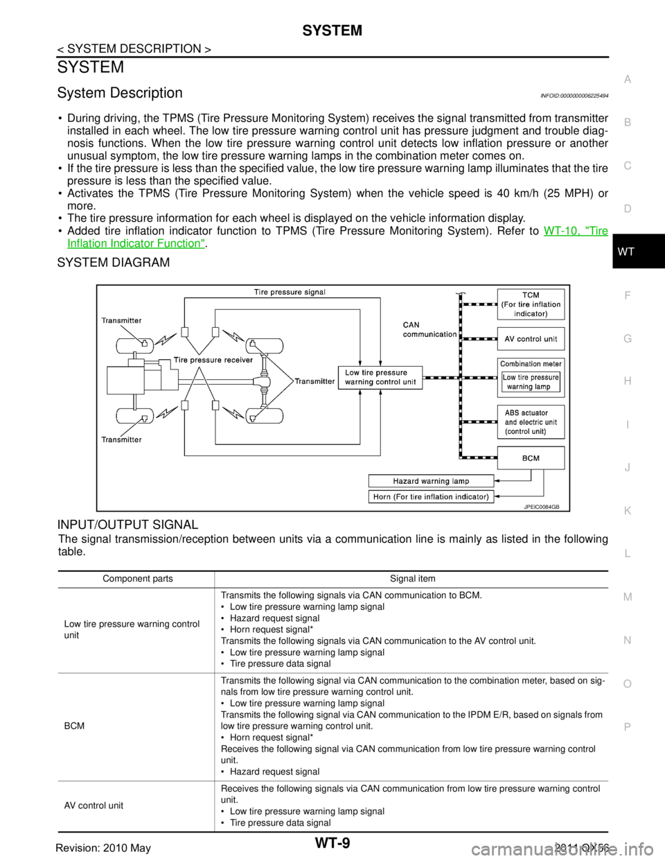
During driving, the TPMS (Tire Pressure Monitoring System) receives the signal transmitted from transmitter
installed in each wheel. The low tire pressure warning control unit has pressure judgment and trouble diag-
nosis functions. When the low tire pressure warning control unit detects low inflation pressure or another
unusual symptom, the low tire pressure warning lamps in the combination meter comes on.
If the tire pressure is less than the specified value, t he low tire pressure warning lamp illuminates that the tire
pressure is less than the specified value.
Activates the TPMS (Tire Pressure Monitoring Sy stem) when the vehicle speed is 40 km/h (25 MPH) or
more.
The tire pressure information for each wheel is displayed on the vehicle information display.
Added tire inflation indicator function to TPMS (Tire Pressure Monitoring System). Refer to WT-10, "
Tire
Inflation Indicator Function".
SYSTEM DIAGRAM
INPUT/OUTPUT SIGNAL
The signal transmission/reception between units via a comm unication line is mainly as listed in the following
table.
JPEIC0084GB
Component parts Signal item
Low tire pressure warning control
unit Transmits the following signals via CAN communication to BCM.
Low tire pressure
warning lamp signal
Hazard request signal
Horn request signal*
Transmits the following signals via CAN communication to the AV control unit.
Low tire pressure warning lamp signal
Tire pressure data signal
BCM Transmits the following signal via CAN communication to the combination meter, based on sig-
nals from low tire pressure warning control unit.
Low tire pressure
warning lamp signal
Transmits the following signal via CAN communication to the IPDM E/R, based on signals from
low tire pressure wa rning control unit.
Horn request signal*
Receives the following signal via CAN communication from low tire pressure warning control
unit.
Hazard request signal
AV control unit Receives the following signals via CAN communication from low tire pressure warning control
unit.
Low tire pressure
warning lamp signal
Tire pressure data signal
Revision: 2010 May2011 QX56
Page 5462 of 5598

WT-12
< SYSTEM DESCRIPTION >
DIAGNOSIS SYSTEM (LOW TIRE PRESSURE WARNING CONTROL UNIT)
DIAGNOSIS SYSTEM (LOW TIRE PRESSURE WARNING CONTROL
UNIT)
CONSULT-III FunctionINFOID:0000000006225496
APPLICATION ITEMS
CONSULT-III performs the following functions in combinat ion of data reception, instruction, and transmission
via communication lines from low tire pressure warning control unit.
*: The following diagnosis information is erased by erasing.
DTC
ECU IDENTIFICATION
Part number of low tire pressure warning control unit is displayed.
SELF DIAGNOSIS RESULTS
Refer to WT-18, "DTC Index".
DATA MONITOR
ACTIVE TEST
NOTE:
After completing the work below, perform an active test.
1. Check ID registration state and perform self-diagnosis.
2. Erase the self-diagnosis result history.
Mode FUNCTION DESCRIPTION
ECU IDENTIFICATION Displays the part number of low tire pressure warning control unit.
SELF-DIAGNOSIS RESULTS Self-diagnosis result can be quickly read.
*
DATA MONITOR Input and output data of low tire pressure warning control unit can be read.
ACTIVE TESTSends command to the low tire pressure warning control unit to change output signals and check
operation of output system.
WORK SUPPORT Components can be quickly and accurately adjusted.
Monitor item (Unit) Remarks
VHCL SPEED SE
[(km/h) or (MPH)] Vehicle speed is displayed.
AIR PRESS FL
[(kPa), (kg/cm
2) or (Psi)] Air pressure of front LH tires is displayed.
AIR PRESS FR
[(kPa), (kg/cm
2) or (Psi)] Air pressure of front RH tires is displayed.
AIR PRESS RR
[(kPa), (kg/cm
2) or (Psi)] Air pressure of rear
RH tires is displayed.
AIR PRESS RL
[(kPa), (kg/cm
2) or (Psi)] Air pressure of rear
LH tires is displayed.
ID REGST FL1 ID registration status of front LH transmitter is displayed.
ID REGST FR1 ID registration status of front RH transmitter is displayed.
ID REGST RR1 ID registration status of rear RH transmitter is displayed.
ID REGST RL1 ID registration status of rear LH transmitter is displayed.
WARNING LAMP Control status of low tire pressure warning lamp is displayed.
BUZZER Control status of buzzer in combination meter by low tire pressure warning con-
trol unit is displayed.
NOTE:
Not use in TPMS, but displayed.
Revision: 2010 May2011 QX56
Page 5499 of 5598

U1000 CAN COMM CIRCUITWT-49
< DTC/CIRCUIT DIAGNOSIS >
C
DF
G H
I
J
K L
M A
B
WT
N
O P
U1000 CAN COMM CIRCUIT
DescriptionINFOID:0000000006225524
CAN (Controller Area Network) is a serial communication li ne for real time application. It is an on-vehicle mul-
tiplex communication line with high data communication speed and excellent error detection ability. Many elec-
tronic control units are equipped onto a vehicle, and each control unit shares information and links with other
control units during operation (not independent). In CAN communication, control units are connected with 2
communication lines (CAN-H line, CAN-L line) allowing a high rate of information transmission with less wiring.
Each control unit communicates data but selectively reads required data only.
DTC LogicINFOID:0000000006225525
DTC DETECTION LOGIC
DTC CONFIRMATION PROCEDURE
1.PERFORM DTC CONFIRMATION
With CONSULT-III
1. Drive for several minutes at a speed of 40 km/h (25 MPH) or more.
2. Stop the vehicle.
3. Perform self-diagnosis for “AIR PRESSURE MONITOR”.
Is DTC
“U1000” detected?
YES >> Proceed to WT-49, "Diagnosis Procedure".
NO >> INSPECTION END
Diagnosis ProcedureINFOID:0000000006225526
Proceed to LAN-27, "CAN COMMUNICATION SYSTEM : CA N System Specification Chart".
DTC Display item Malfunction detected condition Possible cause
U1000 CAN COMM CIRCUIT Low tire pressure warn
ing control unit is
not communicating CAN communication
signal for 2 seconds or more. CAN communication malfunction
Malfunction of low tire pressure warn-
ing control unit
Revision: 2010 May2011 QX56
Page 5500 of 5598

WT-50
< DTC/CIRCUIT DIAGNOSIS >
U1010 CONTROL UNIT (CAN)
U1010 CONTROL UNIT (CAN)
DescriptionINFOID:0000000006225527
CAN (Controller Area Network) is a serial communication line for real time application. It is an on-vehicle mul-
tiplex communication line with high data communication s peed and excellent error detection ability. Many elec-
tronic control units are equipped onto a vehicle, and each control unit shares information and links with other
control units during operation (not independent). In CA N communication, control units are connected with 2
communication lines (CAN-H line, CAN-L line) allowing a high rate of information transmission with less wiring.
Each control unit communicates data but selectively reads required data only.
DTC LogicINFOID:0000000006225528
DTC DETECTION LOGIC
DTC CONFIRMATION PROCEDURE
1.PERFORM DTC CONFIRMATION
With CONSULT-III
1. Drive for several minutes at a s peed of 40 km/h (25 MPH) or more.
2. Stop the vehicle.
3. Perform self-diagnosis for “AIR PRESSURE MONITOR”.
Is DTC
“U1010” detected?
YES >> Proceed to WT-50, "Diagnosis Procedure".
NO >> INSPECTION END
Diagnosis ProcedureINFOID:0000000006225529
1.CHECK LOW TIRE PRESSURE WARNING CONTROL UNIT
Check low tire pressure warning control uni t harness connector for disconnection or deformation.
Is the inspection result normal?
YES >> Replace low tire pressure warning control unit. Refer to WT-65, "Removal and Installation".
NO >> Repair or replace error-detected parts.
DTC Display item Malfunction detected condition Possible cause
U1010 CONTROL UNIT (CAN) Detecting error during the initial diagno-
sis of CAN controller of low tire pressure
warning control unit.Malfunction of low tire pressure warning
control unit
Revision: 2010 May2011 QX56
Page 5509 of 5598

TIRE INFLATION INDICATOR DOES NOT ACTIVATEWT-59
< SYMPTOM DIAGNOSIS >
C
DF
G H
I
J
K L
M A
B
WT
N
O P
TIRE INFLATION INDICATOR DOES NOT ACTIVATE
DescriptionINFOID:0000000006225540
The tire inflation indicator does not function while inflat ing a tire when the A/T shift selector position is in P-
range with the ignition switch ON or with the engine started.
NOTE:
After starting to inflate the tire, it takes a few seconds for the tire inflation indicator to function.
If there is no response for approximately 15 seconds or mo re after inflating the tires, cancel the use of the
tire inflation indicator function or move the vehicle approximately 1 m (3.2 ft) backward or forward to try
again. The air filler pressure may be weak or out of service area.
For tire inflation indicator, Refer to WT-10, "
Tire Inflation Indicator Function".
Diagnosis ProcedureINFOID:0000000006225541
1. LOCATION CHANGE
Move the vehicle to other area and repeat the procedure of the tire inflation indicator function. Refer to WT-10,
"Tire Inflation Indicator Function".
Is the function normal?
YES >> Normal (the tire inflation indicator may not operate, depending on reception condition.)
NO >> GO TO 2.
2.PERFORM LOW TIRE PRESSURE WARNI NG CONTROL UNIT SELF-DIAGNOSIS
With CONSULT-III
1. Drive for 10 minutes at a speed of 40 km/h (25 MPH) or more.
2. Stop the vehicle.
3. Perform self-diagnosis for “AIR PRESSURE MONITOR”.
Is any DTC detected?
YES >> Perform trouble diagnosis for detected DTC. Refer to WT-18, "DTC Index".
NO >> GO TO 3.
3.CHECK HAZARD WARNING LAMP OPERATION
Check hazard warning lamp operation with hazard switch.
Does the hazard warning lamp blink?
YES >> GO TO 4.
NO >> Perform trouble diagnosis for the hazard warning lamp. Refer to EXL-113, "
Symptom Table".
4.PERFORM TCM SELF-DIAGNOSIS
With CONSULT-III
Perform self-diagnosis for “TRANSMISSION”.
Is any DTC detected?
YES >> Check malfunctioning circuit. Refer to TM-78, "DTC Index".
NO >> GO TO 5.
5.CHECK HORN OPERATION
Check horn operation. Refer to SEC-143, "
ComponentFunctionCheck".
Is the operation normal?
YES >> GO TO 6.
NO >> Repair or replace error-detected parts.
6.PERFORM BCM SELF-DIAGNOSIS
With CONSULT-III
Perform self-diagnosis for “BCM”.
Is any DTC detected?
YES >> Check malfunctioning circuit. Refer to BCS-57, "DTCIndex".
NO >> Replace low tire pressure warning control unit. Refer to WT-65, "
Removal and Installation".
Revision: 2010 May2011 QX56