2011 INFINITI QX56 transmission
[x] Cancel search: transmissionPage 2471 of 5598
![INFINITI QX56 2011 Factory Service Manual
P1574 ASCD VEHICLE SPEED SENSOREC-447
< DTC/CIRCUIT DIAGNOSIS > [VK56VD]
C
D
E
F
G H
I
J
K L
M A
EC
NP
O
P1574 ASCD VEHICLE SPEED SENSOR
DescriptionINFOID:0000000006288349
The ECM receives two vehicl INFINITI QX56 2011 Factory Service Manual
P1574 ASCD VEHICLE SPEED SENSOREC-447
< DTC/CIRCUIT DIAGNOSIS > [VK56VD]
C
D
E
F
G H
I
J
K L
M A
EC
NP
O
P1574 ASCD VEHICLE SPEED SENSOR
DescriptionINFOID:0000000006288349
The ECM receives two vehicl](/manual-img/42/57033/w960_57033-2470.png)
P1574 ASCD VEHICLE SPEED SENSOREC-447
< DTC/CIRCUIT DIAGNOSIS > [VK56VD]
C
D
E
F
G H
I
J
K L
M A
EC
NP
O
P1574 ASCD VEHICLE SPEED SENSOR
DescriptionINFOID:0000000006288349
The ECM receives two vehicle speed signals by the CAN
communication line. One is sent from “combination
meter”, and the other is from TCM (Transmission cont rol module). The ECM uses these signals for ASCD con-
trol. Refer to EC-48, "
AUTOMATIC SPEED CONTROL DEVICE (ASCD) : System Description" for ASCD func-
tions.
DTC LogicINFOID:0000000006288350
DTC DETECTION LOGIC
NOTE:
If DTC P1574 is displayed with DTC UXXXX, perform the trouble diagnosis for DTC UXXXX.
If DTC P1574 is displayed with DTC P0500, perform the trouble diagnosis for DTC P0500. Refer to
EC-356, "
DTC Logic".
If DTC P1574 is displayed with DTC P0605, perform the trouble diagnosis for DTC P0605. Refer to
EC-376, "
DTC Logic".
If DTC P1574 is displayed with DTC P0607, perform the trouble diagnosis for DTC P0607. Refer to
EC-378, "
DTC Logic".
DTC CONFIRMATION PROCEDURE
1.PRECONDITIONING
1. Turn ignition switch OFF and wait at least 10 seconds.
2. Turn ignition switch ON.
3. Turn ignition switch OFF and wait at least 10 seconds.
>> GO TO 2.
2.PERFORM DTC CONFIRMATION PROCEDURE
1. Start engine (VDC switch OFF).
2. Drive the vehicle at more than 40 km/h (25 MPH). CAUTION:
Always drive vehicle at a safe speed.
NOTE:
This procedure may be conducted with the drive wheel s lifted in the shop or by driving the vehicle.
If a road test is expected to be easier , it is unnecessary to lift the vehicle.
3. Check DTC.
Is DTC detected?
YES >> Proceed to EC-449, "Diagnosis Procedure".
NO >> INSPECTION END
Diagnosis ProcedureINFOID:0000000006288351
1.CHECK DTC WITH TCM
Check DTC with TCM. Refer to TM-61, "
CONSULT-III Function (TRANSMISSION)".
Is the inspection result normal?
DTC No. Trouble diagnosis name
(Trouble diagnosis content) DTC detecting condition Possible cause
P1574 ASCD VHL SPD SEN
(ASCD vehicle speed sensor) ECM detects a difference between two vehicle
speed signals is out of the specified range. Harness or connectors
(The CAN communication line is open
or shorted.)
Combination meter
ABS actuator and elec tric unit (control
unit)
Wheel sensor
TCM
ECM
Revision: 2010 May2011 QX56
Page 2473 of 5598
![INFINITI QX56 2011 Factory Service Manual
P1574 ICC VEHICLE SPEED SENSOR
EC-449
< DTC/CIRCUIT DIAGNOSIS > [VK56VD]
C
D
E
F
G H
I
J
K L
M A
EC
NP
O
P1574 ICC VEHICLE SPEED SENSOR
DescriptionINFOID:0000000006288352
The ECM receives two vehicle INFINITI QX56 2011 Factory Service Manual
P1574 ICC VEHICLE SPEED SENSOR
EC-449
< DTC/CIRCUIT DIAGNOSIS > [VK56VD]
C
D
E
F
G H
I
J
K L
M A
EC
NP
O
P1574 ICC VEHICLE SPEED SENSOR
DescriptionINFOID:0000000006288352
The ECM receives two vehicle](/manual-img/42/57033/w960_57033-2472.png)
P1574 ICC VEHICLE SPEED SENSOR
EC-449
< DTC/CIRCUIT DIAGNOSIS > [VK56VD]
C
D
E
F
G H
I
J
K L
M A
EC
NP
O
P1574 ICC VEHICLE SPEED SENSOR
DescriptionINFOID:0000000006288352
The ECM receives two vehicle speed signals by the CAN
communication line. One is sent from “combination
meter”, and the other is from TCM (Transmission cont rol module). The ECM uses these signals for ICC con-
trol. Refer to CCS-12, "
System Description" for ICC functions.
DTC LogicINFOID:0000000006288353
DTC DETECTION LOGIC
NOTE:
If DTC P1574 is displayed with DTC UXXXX, first perform the tr ouble diagnosis for DTC UXXXX.
If DTC P1574 is displayed with DT C P0500, first perform the trouble diagnosis for DTC P0500. Refer
to EC-356, "
DTC Logic".
If DTC P1574 is displayed with DT C P0605, first perform the trouble diagnosis for DTC P0605. Refer
to EC-376, "
DTC Logic".
If DTC P1574 is displayed with DT C P0607, first perform the trouble diagnosis for DTC P0607. Refer
to EC-378, "
DTC Logic".
DTC CONFIRMATION PROCEDURE
1.PRECONDITIONING
1. Turn ignition switch OFF and wait at least 10 seconds.
2. Turn ignition switch ON.
3. Turn ignition switch OFF and wait at least 10 seconds.
>> GO TO 2.
2.PERFORM DTC CONFIRMATION PROCEDURE
1. Start engine (VDC switch OFF).
2. Drive the vehicle at more than 40 km/h (25 MPH). CAUTION:
Always drive vehicle at a safe speed.
NOTE:
This procedure may be conducted with the drive wheel s lifted in the shop or by driving the vehicle.
If a road test is expected to be easier , it is unnecessary to lift the vehicle.
3. Check DTC.
Is DTC detected?
YES >> Proceed to EC-449, "Diagnosis Procedure".
NO >> INSPECTION END
Diagnosis ProcedureINFOID:0000000006288354
1.CHECK DTC WITH TCM
Check DTC with TCM. Refer to TM-61, "
CONSULT-III Function (TRANSMISSION)".
Is the inspection result normal?
YES >> GO TO 2.
DTC No. Trouble diagnosis name
(Trouble diagnosis content) DTC detecting condition Possible cause
P1574 ASCD VHL SPD SEN
(ICC vehicle speed sensor) ECM detects a difference between two vehicle
speed signals is out of the specified range. Harness or connectors
(The CAN communication line is open or
shorted.)
Combination meter
ABS actuator and electric unit (control unit)
Wheel sensor
TCM
ECM
Revision: 2010 May2011 QX56
Page 2620 of 5598
EM-58
< REMOVAL AND INSTALLATION >
OIL PAN (UPPER)
Removal and Installation
INFOID:0000000006289563
REMOVAL
WARNING:
To avoid the danger of being scalded, never drain engine oil when engine is hot.
1. Remove oil filter. Refer to LU-9, "
Removal and Installation".
2. Remove oil cooler. Refer to LU-11, "
Exploded View".
3. Move A/C compressor to the position without the hindrance for work. Refer to HA-30, "
Exploded View".
4. Remove oil level gauge and oil level gauge guide.
5. Remove oil pressure switch and oil temperature sensor if necessary.
6. Remove rear plate cover.
7. Remove protector A and protector B. Refer to SCS-32, "
FRONT TUBE ASSEMBLY : Exploded View".
8. Remove front suspension rear cross member. Refer to TM-205, "
2WD : Exploded View" (2WD models) or
TM-208, "
4WD : Exploded View" (4WD models).
9. Remove steering gear assembly. Refer to ST-41, "
Exploded View".
10. Remove front final drive assembly. Refer to DLN-162, "
Exploded View".
11. Remove oil pan (lower). Refer to EM-54, "
Exploded View".
12. Remove oil strainer. Refer to EM-54, "
Exploded View".
13. Remove bolts fixing oil pan (upper) to transmission assembly.
14. Remove oil pan (upper) as per the following:
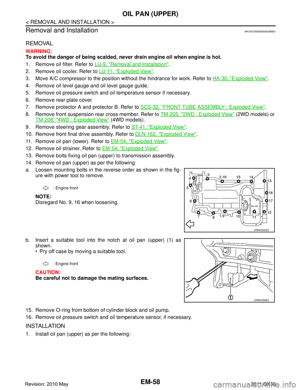
a. Loosen mounting bolts in the reverse order as shown in the fig- ure with power tool to remove.
NOTE:
Disregard No. 9, 16 when loosening.
b. Insert a suitable tool into the notch at oil pan (upper) (1) as shown.
Pry off case by moving a suitable tool.
CAUTION:
Be careful not to damage the mating surfaces.
15. Remove O-ring from bottom of cylinder block and oil pump.
16. Remove oil pressure switch and oil temperature sensor, if necessary.
INSTALLATION
1. Install oil pan (upper) as per the following:
: Engine front
JPBIA3502ZZ
: Engine front
JPBIA2299ZZ
Revision: 2010 May2011 QX56
Page 2621 of 5598
OIL PAN (UPPER)EM-59
< REMOVAL AND INSTALLATION >
C
DE
F
G H
I
J
K L
M A
EM
NP
O
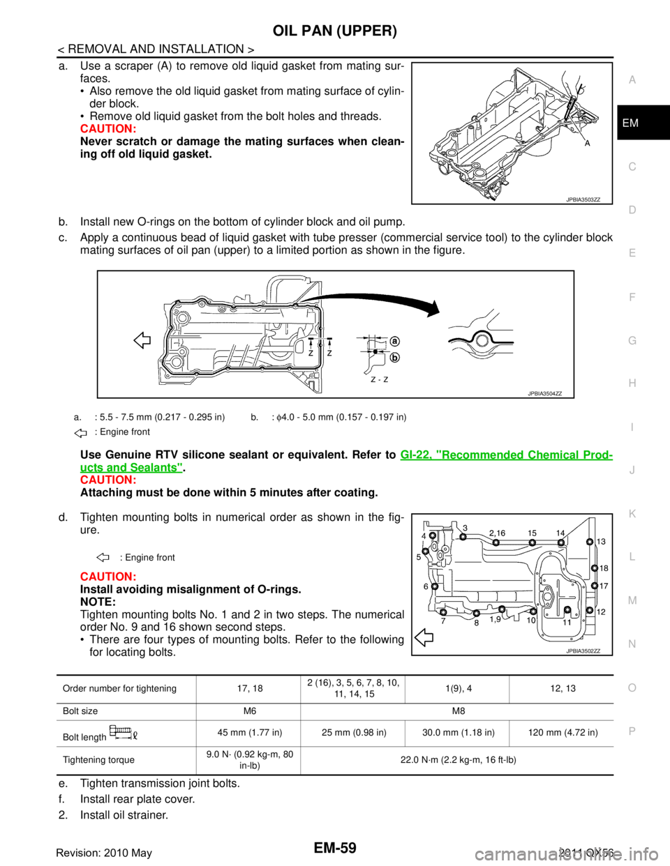
a. Use a scraper (A) to remove old liquid gasket from mating sur-
faces.
Also remove the old liquid gasket from mating surface of cylin-der block.
Remove old liquid gasket from the bolt holes and threads.
CAUTION:
Never scratch or damage th e mating surfaces when clean-
ing off old liquid gasket.
b. Install new O-rings on the bottom of cylinder block and oil pump.
c. Apply a continuous bead of liquid gasket with tube pre sser (commercial service tool) to the cylinder block
mating surfaces of oil pan (upper) to a limited portion as shown in the figure.
Use Genuine RTV silicone sealant or equivalent. Refer to GI-22, "
Recommended Chemical Prod-
ucts and Sealants".
CAUTION:
Attaching must be done with in 5 minutes after coating.
d. Tighten mounting bolts in numerical order as shown in the fig- ure.
CAUTION:
Install avoiding misal ignment of O-rings.
NOTE:
Tighten mounting bolts No. 1 and 2 in two steps. The numerical
order No. 9 and 16 shown second steps.
There are four types of mounting bolts. Refer to the following for locating bolts.
e. Tighten transmission joint bolts.
f. Install rear plate cover.
2. Install oil strainer.
JPBIA3503ZZ
a. : 5.5 - 7.5 mm (0.217 - 0.295 in) b. : φ4.0 - 5.0 mm (0.157 - 0.197 in)
: Engine front
JPBIA3504ZZ
: Engine front
JPBIA3502ZZ
Order number for tightening 17, 18 2 (16), 3, 5, 6, 7, 8, 10,
11, 14, 15 1(9), 4 12, 13
Bolt size M6 M8
Bolt length 45 mm (1.77 in) 25 mm (0.98 in) 30.0 mm (1.18 in) 120 mm (4.72 in)
Tightening torque 9.0 N· (0.92 kg-m, 80
in-lb) 22.0 N·m (2.2 kg-m, 16 ft-lb)
Revision: 2010 May2011 QX56
Page 2635 of 5598
TIMING CHAINEM-73
< REMOVAL AND INSTALLATION >
C
DE
F
G H
I
J
K L
M A
EM
NP
O
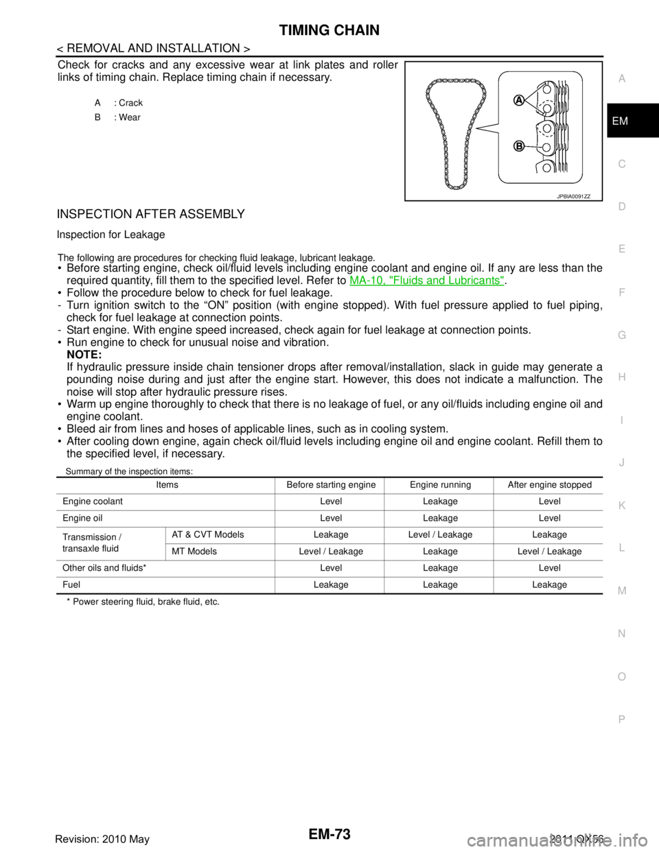
Check for cracks and any excessive
wear at link plates and roller
links of timing chain. Replace timing chain if necessary.
INSPECTION AFTER ASSEMBLY
Inspection for Leakage
The following are procedures for chec king fluid leakage, lubricant leakage. Before starting engine, check oil/fluid levels including engine coolant and engine oil. If any are less than the
required quantity, fill them to the specified level. Refer to MA-10, "
Fluids and Lubricants".
Follow the procedure below to check for fuel leakage.
- Turn ignition switch to the “ON” position (with engi ne stopped). With fuel pressure applied to fuel piping,
check for fuel leakage at connection points.
- Start engine. With engine speed increased, check again for fuel leakage at connection points.
Run engine to check for unusual noise and vibration.
NOTE:
If hydraulic pressure inside chain tensioner drops after removal/installation, slack in guide may generate a
pounding noise during and just after the engine start. However, this does not indicate a malfunction. The
noise will stop after hydraulic pressure rises.
Warm up engine thoroughly to check that there is no leak age of fuel, or any oil/fluids including engine oil and
engine coolant.
Bleed air from lines and hoses of applicable lines, such as in cooling system.
After cooling down engine, again check oil/fluid levels including engine oil and engine coolant. Refill them to the specified level, if necessary.
Summary of the inspection items:
* Power steering fluid, brake fluid, etc. A: Crack
B: Wear
JPBIA0091ZZ
Items Before starting engine Engine running After engine stopped
Engine coolant Level Leakage Level
Engine oil Level Leakage Level
Transmission /
transaxle fluid AT & CVT Models Leakage Level / Leakage Leakage
MT Models Level / Leakage Leakage Level / Leakage
Other oils and fluids* Level Leakage Level
Fuel Leakage Leakage Leakage
Revision: 2010 May2011 QX56
Page 2647 of 5598
CAMSHAFTEM-85
< REMOVAL AND INSTALLATION >
C
DE
F
G H
I
J
K L
M A
EM
NP
O
5. Perform the following inspection if engine oil does not
come out from valve timing control solenoid valve
oil hole of the valve timing control cover.
Remove oil filter, and then clean it. Refer to EM-61, "
Exploded View".
Clean oil groove between oil strainer and valve timing control solenoid valve. Refer to LU-5, "
Engine
Lubrication System" and LU-6, "Engine Lubrication System Schematic".
6. Remove components between valve timing control solenoid valve and camshaft sprocket, and then check each oil groove for clogging.
Clean oil groove if necessary. Refer to LU-5, "
Engine Lubrication System" and LU-6, "Engine Lubrica-
tion System Schematic".
7. After inspection, install removed parts in the reverse order.
Inspection for Leakage
The following are procedures for chec king fluid leakage, lubricant leakage.
Before starting engine, check oil/fluid levels including engine coolant and engine oil. If any are less than the
required quantity, fill them to the specified level. Refer to MA-10, "
Fluids and Lubricants".
Follow the procedure below to check for fuel leakage.
- Turn ignition switch to the “ON” position (with engi ne stopped). With fuel pressure applied to fuel piping,
check for fuel leakage at connection points.
- Start engine. With engine speed increased, check again for fuel leakage at connection points.
Run engine to check for unusual noise and vibration. NOTE:
If hydraulic pressure inside chain tensioner drops after removal/installation, slack in guide may generate a
pounding noise during and just after the engine start. However, this does not indicate a malfunction. The
noise will stop after hydraulic pressure rises.
Warm up engine thoroughly to check that there is no leak age of fuel, or any oil/fluids including engine oil and
engine coolant.
Bleed air from lines and hoses of applicable lines, such as in cooling system.
After cooling down engine, again check oil/fluid levels including engine oil and engine coolant. Refill them to
the specified level, if necessary.
Summary of the inspection items:
* Power steering fluid, brake fluid, etc. Items Before starting engine Engine running After engine stopped
Engine coolant Level Leakage Level
Engine oil Level Leakage Level
Transmission /
transaxle fluid AT & CVT Models Leakage Level / Leakage Leakage
MT Models Level / Leakage Leakage Level / Leakage
Other oils and fluids* Level Leakage Level
Fuel Leakage Leakage Leakage
Revision: 2010 May2011 QX56
Page 2657 of 5598
CYLINDER HEADEM-95
< REMOVAL AND INSTALLATION >
C
DE
F
G H
I
J
K L
M A
EM
NP
O
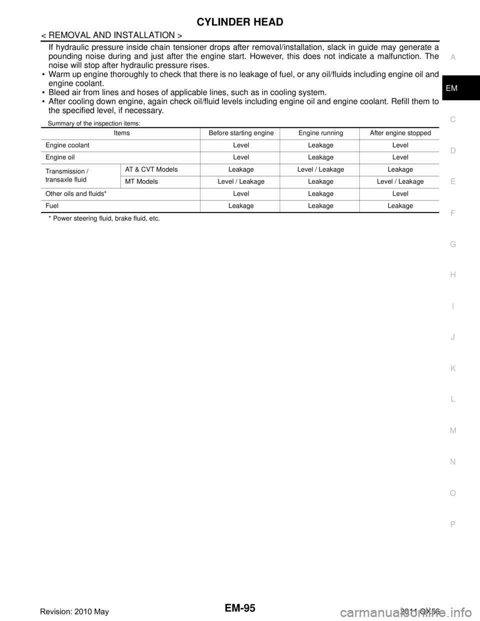
If hydraulic pressure inside chain tensioner drops after removal/installation, slack in guide may generate a
pounding noise during and just after the engine start. However, this does not indicate a malfunction. The
noise will stop after hydraulic pressure rises.
Warm up engine thoroughly to check that there is no leak age of fuel, or any oil/fluids including engine oil and
engine coolant.
Bleed air from lines and hoses of applicable lines, such as in cooling system.
After cooling down engine, again check oil/fluid levels including engine oil and engine coolant. Refill them to
the specified level, if necessary.
Summary of the inspection items:
* Power steering fluid, brake fluid, etc. Items Before starting engine Engine running After engine stopped
Engine coolant Level Leakage Level
Engine oil Level Leakage Level
Transmission /
transaxle fluid AT & CVT Models Leakage Level / Leakage Leakage
MT Models Level / Leakage Leakage Level / Leakage
Other oils and fluids* Level Leakage Level
Fuel Leakage Leakage Leakage
Revision: 2010 May2011 QX56
Page 2659 of 5598
OIL SEALEM-97
< REMOVAL AND INSTALLATION >
C
DE
F
G H
I
J
K L
M A
EM
NP
O
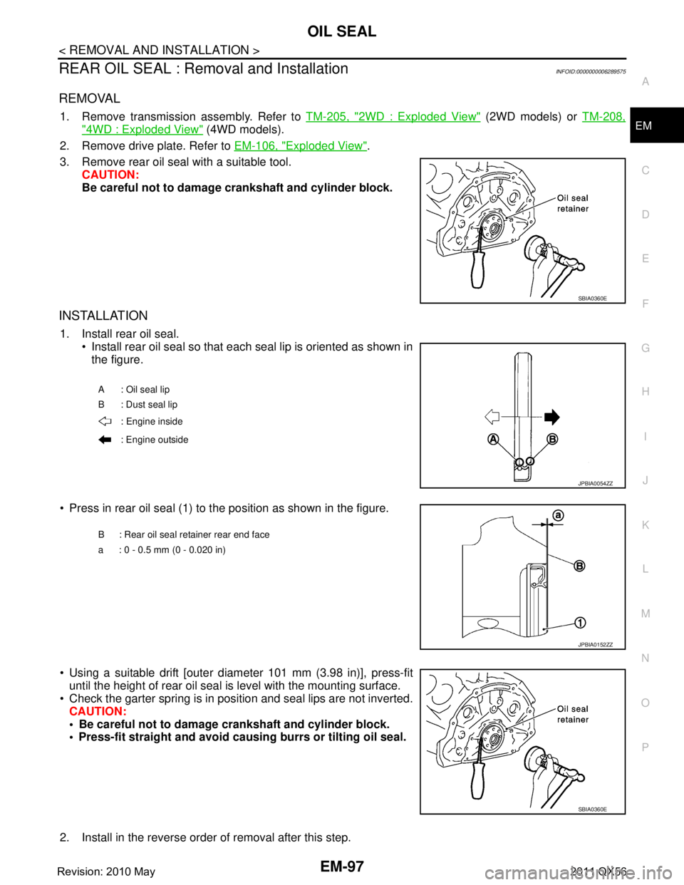
REAR OIL SEAL : Removal and InstallationINFOID:0000000006289575
REMOVAL
1. Remove transmission assembly. Refer to
TM-205, "2WD : Exploded View" (2WD models) or TM-208,
"4WD : Exploded View" (4WD models).
2. Remove drive plate. Refer to EM-106, "
Exploded View".
3. Remove rear oil seal with a suitable tool. CAUTION:
Be careful not to damage crankshaft and cylinder block.
INSTALLATION
1. Install rear oil seal. Install rear oil seal so that each seal lip is oriented as shown in
the figure.
Press in rear oil seal (1) to the position as shown in the figure.
Using a suitable drift [outer diameter 101 mm (3.98 in)], press-fit until the height of rear oil seal is level with the mounting surface.
Check the garter spring is in position and seal lips are not inverted. CAUTION:
Be careful not to damage crankshaft and cylinder block.
Press-fit straight and avoid cau sing burrs or tilting oil seal.
2. Install in the reverse order of removal after this step.
SBIA0360E
A : Oil seal lip
B : Dust seal lip : Engine inside
: Engine outside
JPBIA0054ZZ
B : Rear oil seal retainer rear end face
a : 0 - 0.5 mm (0 - 0.020 in)
JPBIA0152ZZ
SBIA0360E
Revision: 2010 May2011 QX56