2011 INFINITI QX56 transmission
[x] Cancel search: transmissionPage 2998 of 5598
GI-34
< PRECAUTION >
TOW TRUCK TOWING
TOW TRUCK TOWING
Tow Truck TowingINFOID:0000000006280880
CAUTION:
All applicable local laws regarding the towing operation must be obeyed.
It is necessary to use proper towi ng equipment to avoid possible damage to the vehicle during tow-
ing operation. To wing is in accordance with Towing Procedure Manual at dealer.
Always attach safety chains before towing.
When towing, check that the transmission, steering syst em and powertrain are in good order. If any
unit is damaged, dollies must be used.
Never tow automatic transmission model from the rear (that is backward) with four wheels on the
ground. This may cause serious and exp ensive damage to the transmission.
4WD MODELS
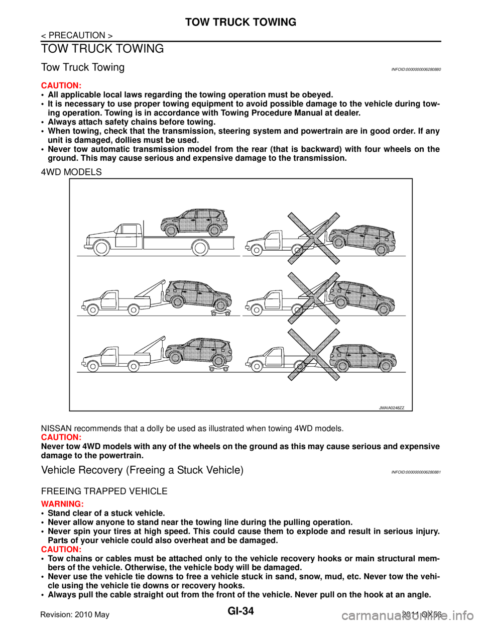
NISSAN recommends that a dolly be used as illustrated when towing 4WD models.
CAUTION:
Never tow 4WD models with any of the wheels on the ground as this may cause serious and expensive
damage to the powertrain.
Vehicle Recovery (Freeing a Stuck Vehicle)INFOID:0000000006280881
FREEING TRAPPED VEHICLE
WARNING:
Stand clear of a stuck vehicle.
Never allow anyone to stand near the towing line during the pulling operation.
Never spin your tires at high sp eed. This could cause them to explode and result in serious injury.
Parts of your vehicle could also overheat and be damaged.
CAUTION:
Tow chains or cables must be attached only to the vehicle recovery hooks or main structural mem-
bers of the vehicle. Otherwise, the vehicle body will be damaged.
Never use the vehicle tie downs to free a vehicle st uck in sand, snow, mud, etc. Never tow the vehi-
cle using the vehicle tie downs or recovery hooks.
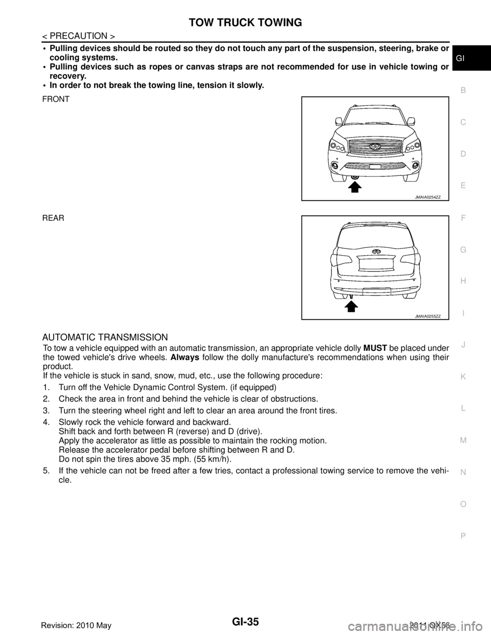
Always pull the cable straight out from the front of the vehicle. Never pull on the hook at an angle.
JMAIA0248ZZ
Revision: 2010 May2011 QX56
Page 2999 of 5598
TOW TRUCK TOWINGGI-35
< PRECAUTION >
C
DE
F
G H
I
J
K L
M B
GI
N
O P
Pulling devices should be routed so they do not touch any part of the suspension, steering, brake or
cooling systems.
Pulling devices such as ropes or canvas straps ar e not recommended for use in vehicle towing or
recovery.
In order to not break the towi ng line, tension it slowly.
FRONT
REAR
AUTOMATIC TRANSMISSION
To tow a vehicle equipped with an automatic tr ansmission, an appropriate vehicle dolly MUST be placed under
the towed vehicle's drive wheels. Always follow the dolly manufacture's recommendations when using their
product.
If the vehicle is stuck in sand, snow , mud, etc., use the following procedure:
1. Turn off the Vehicle Dynam ic Control System. (if equipped)
2. Check the area in front and behind the vehicle is clear of obstructions.
3. Turn the steering wheel right and left to clear an area around the front tires.
4. Slowly rock the vehicle forward and backward. Shift back and forth between R (reverse) and D (drive).
Apply the accelerator as little as possible to maintain the rocking motion.
Release the accelerator pedal before shifting between R and D.
Do not spin the tires above 35 mph. (55 km/h).
5. If the vehicle can not be freed after a few tries, cont act a professional towing service to remove the vehi-
cle.
JMAIA0254ZZ
JMAIA0255ZZ
Revision: 2010 May2011 QX56
Page 3000 of 5598
GI-36
< BASIC INSPECTION >
SERVICE INFORMATION FOR ELECTRICAL INCIDENT
BASIC INSPECTION
SERVICE INFORMATION FOR ELECTRICAL INCIDENT
Work FlowINFOID:0000000006280851
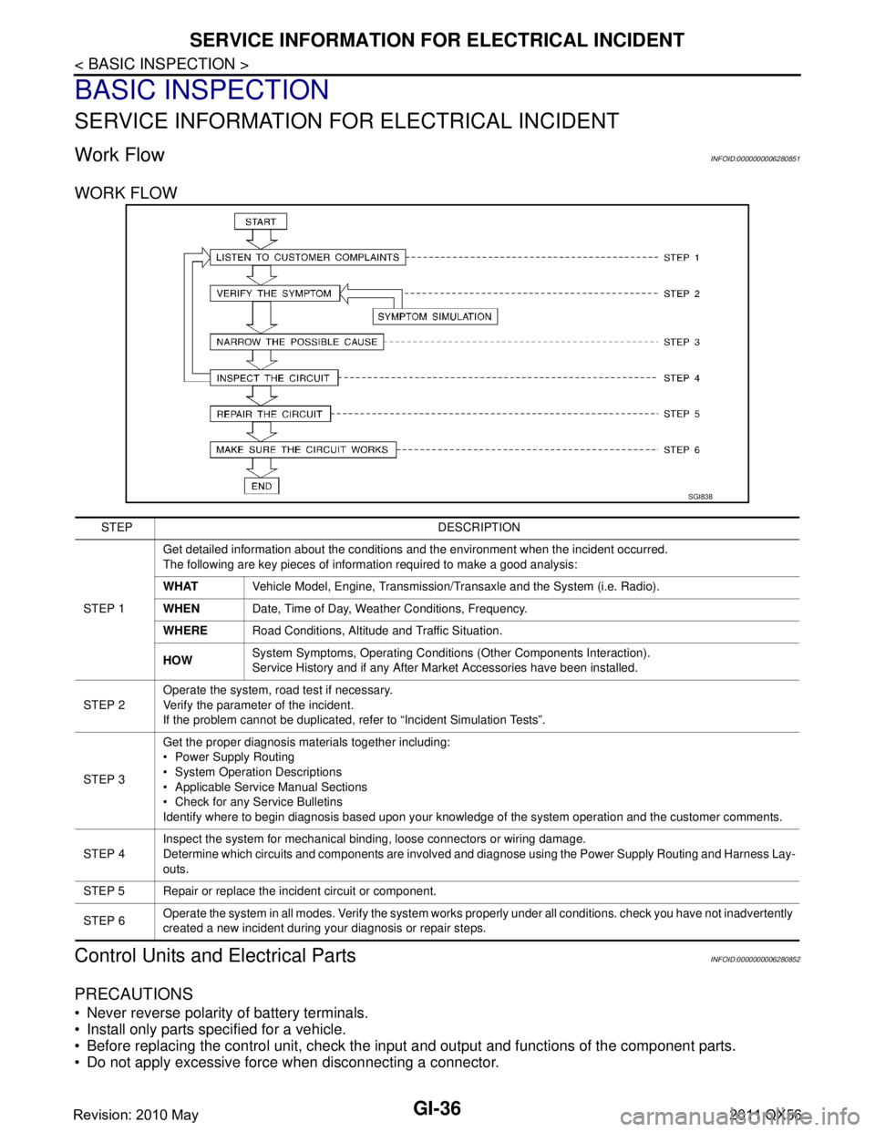
WORK FLOW
Control Units and Electrical PartsINFOID:0000000006280852
PRECAUTIONS
Never reverse polarity of battery terminals.
Install only parts specified for a vehicle.
Before replacing the control unit, check the i nput and output and functions of the component parts.
Do not apply excessive force when disconnecting a connector.
SGI838
STEP DESCRIPTION
STEP 1 Get detailed information about the conditions and the environment when the incident occurred.
The following are key pieces of information required to make a good analysis:
WHAT
Vehicle Model, Engine, Transmission/Transaxle and the System (i.e. Radio).
WHEN Date, Time of Day, Weather Conditions, Frequency.
WHERE Road Conditions, Altitude and Traffic Situation.
HOW System Symptoms, Operating Conditions
(Other Components Interaction).
Service History and if any After Market Accessories have been installed.
STEP 2 Operate the system, road test if necessary.
Verify the parameter of the incident.
If the problem cannot be duplicated, refer to “Incident Simulation Tests”.
STEP 3 Get the proper diagnosis materials together including:
Power Supply Routing
System Operation Descriptions
Applicable Service Manual Sections
Check for any Service Bulletins
Identify where to begin diagnosis based upon your knowledge of the system operation and the customer comments.
STEP 4 Inspect the system for mechanical binding, loose connectors or wiring damage.
Determine which circuits and components are involved and diagnose using the Power Supply Routing and Harness Lay-
outs.
STEP 5 Repair or replace the incident circuit or component.
STEP 6 Operate the system in all modes. Verify the system works properly under all conditions. check you have not inadvertently
created a new incident during your diagnosis or repair steps.
Revision: 2010 May2011 QX56
Page 3012 of 5598
GI-48
< BASIC INSPECTION >
CONSULT-III/GST CHECKING SYSTEM
CONSULT-III/GST CHECKING SYSTEM
DescriptionINFOID:0000000006280856
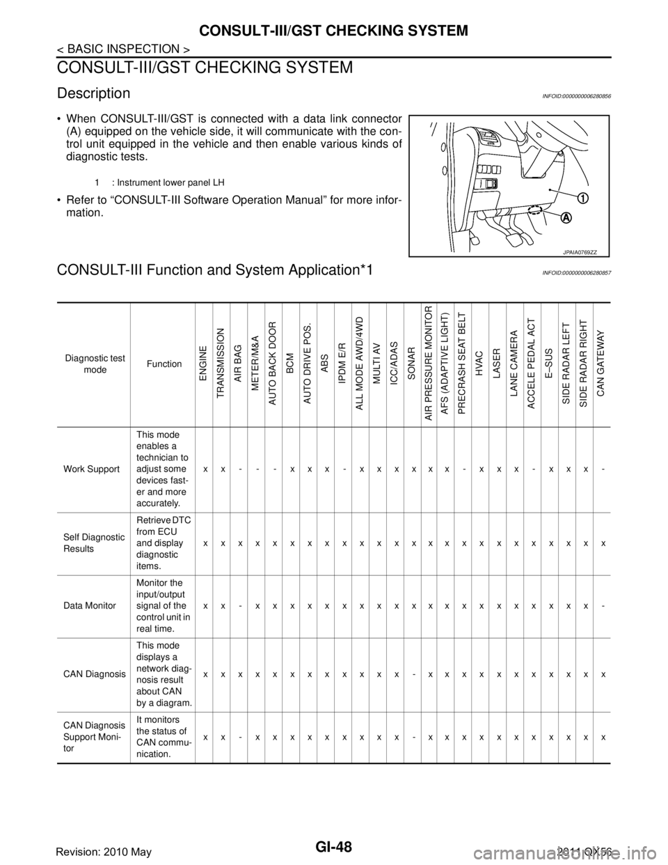
When CONSULT-III/GST is connected with a data link connector
(A) equipped on the vehicle side, it will communicate with the con-
trol unit equipped in the vehicle and then enable various kinds of
diagnostic tests.
Refer to “CONSULT-III Software Operation Manual” for more infor- mation.
CONSULT-III Function a nd System Application*1INFOID:0000000006280857
1 : Instrument lower panel LH
JPAIA0769ZZ
Diagnostic test
mode Function
ENGINE
TRANSMISSION AIR BAG
METER/M&A
AUTO BACK DOOR BCM
AUTO DRIVE POS. ABS
IPDM E/R
ALL MODE AWD/4WD MULTI AV
ICC/ADAS SONAR
AIR PRESSURE MONITOR AFS (ADAPTIVE LIGHT)
PRECRASH SEAT BELT HVAC
LASER
LANE CAMERA
ACCELE PEDAL ACT
E–SUS
SIDE RADAR LEFT
SIDE RADAR RIGHT CAN GATEWAY
Work Support This mode
enables a
technician to
adjust some
devices fast-
er and more
accurately.xx - - - xxx - xxxxxx - xxx - xxx -
Self Diagnostic
Results Retrieve DTC
from ECU
and display
diagnostic
items.
xxxxxxxxxxxxxxxxxxxxxxxx
Data Monitor Monitor the
input/output
signal of the
control unit in
real time.xx - xxxxxxxxxxxxxxxxxxxx -
CAN Diagnosis This mode
displays a
network diag-
nosis result
about CAN
by a diagram.xxxxxxxxxxxx -xxxxxxxxxxx
CAN Diagnosis
Support Moni-
tor It monitors
the status of
CAN commu-
nication.
xx - xxxxxxxxx -xxxxxxxxxxx
Revision: 2010 May2011 QX56
Page 3013 of 5598
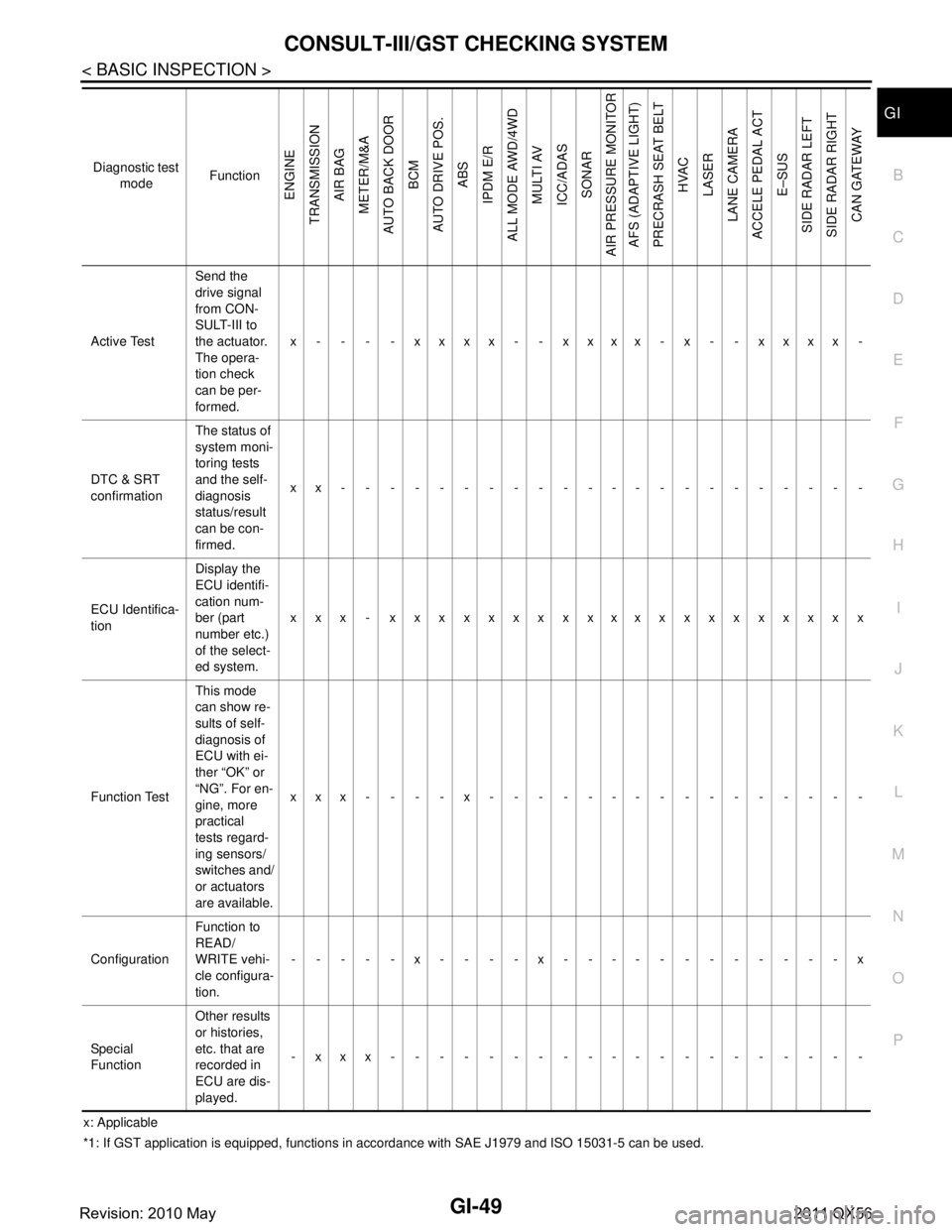
CONSULT-III/GST CHECKING SYSTEMGI-49
< BASIC INSPECTION >
C
DE
F
G H
I
J
K L
M B
GI
N
O P
x: Applicable
*1: If GST application is equipped , functions in accordance with SAE J1 979 and ISO 15031-5 can be used.
Active Test
Send the
drive signal
from CON-
SULT-III to
the actuator.
The opera-
tion check
can be per-
formed.x - - - - xxxx - - xxxx - x - - xxxx -
DTC & SRT
confirmation The status of
system moni-
toring tests
and the self-
diagnosis
status/result
can be con-
firmed.
xx----------------------
ECU Identifica-
tion Display the
ECU identifi-
cation num-
ber (part
number etc.)
of the select-
ed system.
xxx - xxxxxxxxxxxxxxxxxxxx
Function Test This mode
can show re-
sults of self-
diagnosis of
ECU with ei-
ther “OK” or
“NG”. For en-
gine, more
practical
tests regard-
ing sensors/
switches and/
or actuators
are available.xxx----x----------------
Configuration Function to
READ/
WRITE vehi-
cle configura-
tion.-----x----x------------x
Special
Function Other results
or histories,
etc. that are
recorded in
ECU are dis-
played.
-xxx--------------------
Diagnostic test
mode Function
ENGINE
TRANSMISSION AIR BAG
METER/M&A
AUTO BACK DOOR
BCM
AUTO DRIVE POS. ABS
IPDM E/R
ALL MODE AWD/4WD
MULTI AV
ICC/ADAS SONAR
AIR PRESSURE MONITOR AFS (ADAPTIVE LIGHT)
PRECRASH SEAT BELT HVAC
LASER
LANE CAMERA
ACCELE PEDAL ACT E–SUS
SIDE RADAR LEFT
SIDE RADAR RIGHT CAN GATEWAY
Revision: 2010 May2011 QX56
Page 3178 of 5598
![INFINITI QX56 2011 Factory Service Manual
HAC-72
< DTC/CIRCUIT DIAGNOSIS >[AUTOMATIC AIR CONDITIONING]
U1000 CAN COMM CIRCUIT
DTC/CIRCUIT DIAGNOSIS
U1000 CAN COMM CIRCUIT
DescriptionINFOID:0000000006275903
CAN (Controller Area Network) is a INFINITI QX56 2011 Factory Service Manual
HAC-72
< DTC/CIRCUIT DIAGNOSIS >[AUTOMATIC AIR CONDITIONING]
U1000 CAN COMM CIRCUIT
DTC/CIRCUIT DIAGNOSIS
U1000 CAN COMM CIRCUIT
DescriptionINFOID:0000000006275903
CAN (Controller Area Network) is a](/manual-img/42/57033/w960_57033-3177.png)
HAC-72
< DTC/CIRCUIT DIAGNOSIS >[AUTOMATIC AIR CONDITIONING]
U1000 CAN COMM CIRCUIT
DTC/CIRCUIT DIAGNOSIS
U1000 CAN COMM CIRCUIT
DescriptionINFOID:0000000006275903
CAN (Controller Area Network) is a serial communication
system for real time application. It is an on-vehicle
multiplex communication system with high data comm unication speed and excellent error detection ability.
Many electronic control units are equipped onto vehicl es, and each control unit shares information and links
with other control units during operation (not independent ). In CAN communication, control units are con-
nected with two communication lines (CAN-H line, CAN-L line) allowing a high rate of information transmission
with less wiring. Each control unit transmits/recei ves data but selectively reads required data only.
CAN Communication Signal Chart. Refer to LAN-28, "
CAN COMMUNICATION SYSTEM : CAN Communica-
tion Signal Chart".
DTC LogicINFOID:0000000006275904
DTC DETECTION LOGIC
DTC CONFIRMATION PROCEDURE
1.PERFORM SELF-DIAGNOSIS
With CONSULT-III
1. Turn ignition switch ON and wait for 2 seconds or more.
2. Select “Self Diagnostic Result” m ode of “HVAC” using CONSULT-.III
3. Check DTC.
Is DTC detected?
YES >> Refer to HAC-72, "Diagnosis Procedure".
NO >> Refer to GI-40, "
Intermittent Incident".
Diagnosis ProcedureINFOID:0000000006275905
1.CHECK CAN COMMUNICATION SYSTEM
Check CAN communication system. Refer to LAN-18, "
Trouble Diagnosis Flow Chart".
>> INSPECTION END
DTC Items
(CONSULT-III screen terms) DTC detection condition Possible cause
U1000 CAN COMM CIRCUIT When A/C auto amp. is not transmitting
or receiving CAN communication signal
for 2 or more seconds.
CAN communication system
Revision: 2010 May2011 QX56
Page 3429 of 5598
![INFINITI QX56 2011 Factory Service Manual
LAN
SYSTEMLAN-9
< SYSTEM DESCRIPTION > [CAN FUNDAMENTAL]
C
D
E
F
G H
I
J
K L
B A
O P
N
CAN COMMUNICATION SYSTEM : CA
N Communication Control CircuitINFOID:0000000006220514
*: These are the only contr INFINITI QX56 2011 Factory Service Manual
LAN
SYSTEMLAN-9
< SYSTEM DESCRIPTION > [CAN FUNDAMENTAL]
C
D
E
F
G H
I
J
K L
B A
O P
N
CAN COMMUNICATION SYSTEM : CA
N Communication Control CircuitINFOID:0000000006220514
*: These are the only contr](/manual-img/42/57033/w960_57033-3428.png)
LAN
SYSTEMLAN-9
< SYSTEM DESCRIPTION > [CAN FUNDAMENTAL]
C
D
E
F
G H
I
J
K L
B A
O P
N
CAN COMMUNICATION SYSTEM : CA
N Communication Control CircuitINFOID:0000000006220514
*: These are the only control units wired with both ends of CAN communication system.
DIAG ON CAN
DIAG ON CAN : DescriptionINFOID:0000000006220515
“Diag on CAN” is a diagnosis using CAN communication instead of previous DDL1 and DDL2 communication
lines, between control units and diagnosis unit.
SKIB8713E
Component System description
CAN controller It controls CAN communication signal transmission and reception, error detection, etc.
Transceiver IC It converts digital signal into CAN communication signal, and CAN communication signal into digital
signal.
Noise filter It eliminates noise of CAN communication signal.
Termination circuit
*
(Resistance of approx. 120 Ω) It produces potential difference.
Revision: 2010 May2011 QX56
Page 3436 of 5598
![INFINITI QX56 2011 Factory Service Manual
LAN-16
< SYSTEM DESCRIPTION >[CAN FUNDAMENTAL]
TROUBLE DIAGNOSIS
With PAST
MONITOR ITEM (ON-BOARD DIAGNOSIS)
NOTE:
For some models, CAN communication diagnosis result is received from the vehicle mon INFINITI QX56 2011 Factory Service Manual
LAN-16
< SYSTEM DESCRIPTION >[CAN FUNDAMENTAL]
TROUBLE DIAGNOSIS
With PAST
MONITOR ITEM (ON-BOARD DIAGNOSIS)
NOTE:
For some models, CAN communication diagnosis result is received from the vehicle mon](/manual-img/42/57033/w960_57033-3435.png)
LAN-16
< SYSTEM DESCRIPTION >[CAN FUNDAMENTAL]
TROUBLE DIAGNOSIS
With PAST
MONITOR ITEM (ON-BOARD DIAGNOSIS)
NOTE:
For some models, CAN communication diagnosis result is received from the vehicle monitor.
Example: Vehicle Display
Item PRSNT Description
Initial diagnosis OK Normal at present
NG Control unit error (Excep t for some control units)
Transmission diagnosis OK Normal at present
UNKWN Unable to transmit signals for 2 seconds or more.
Diagnosis not performed
Control unit name
(Reception diagnosis) OK Normal at present
UNKWN Unable to receive signals for 2 seconds or more.
Diagnosis not performed
No control unit for receiving signals. (No applicable optional parts)
Item PRSNT PAST Description
Transmission diagnosis OKOK Normal at present and in the past
1 – 39 Normal at present, but unable to transmit signals for 2 seconds or more
in the past. (The number indicates the number of ignition switch cycles
from OFF to ON.)
UNKWN 0 Unable to transmit signals for 2 seconds or more at present.
Control unit name
(Reception diagnosis) OK
OK Normal at present and in the past
1 – 39 Normal at present, but unable to receive signals for 2 seconds or more
in the past. (The number indicates the number of ignition switch cycles
from OFF to ON.)
UNKWN 0 Unable to receive signals for 2 seconds or more at present.
–– Diagnosis not performed.
No control unit for receiving signals. (No applicable optional parts)
Item
Result indi-
cated Error counter Description
CAN_COMM
(Initial diagnosis) OK 0 Normal at present
NG 1 – 50 Control unit error
(The number indicates how many times diagnosis has been
run.)
CAN_CIRC_1
(Transmission diagnosis) OK 0 Normal at present
UNKWN 1 – 50 Unable to transmit for 2 seconds or more at present.
(The number indicates how many times diagnosis has been
run.)
CAN_CIRC_2 – 9
(Reception diagnosis of each unit) OK 0 Normal at present
UNKWN 1 – 50 Unable to transmit for 2 seconds or more at present.
(The number indicates how many times diagnosis has been
run.)
Diagnosis not performed.
No control unit for receiving signals. (No applicable optional
parts)
Revision: 2010 May2011 QX56